User Manual
Page 2
...layouts or drivers without notice. Windows 95/98/98SE/ME/2000/NT and Windows XP are registered trademarks of IBM Corporation. Our products are the property of Phoenix Technologies Ltd. The information provided in this manual. No Warranty VIA has made every effort to the installation ...subject to make changes without notification. However, it may contain technical inaccuracies or typographical or other VIA product. No part of this manual may result from such an inaccuracy, including without express written authorization from the use, disuse or misuse of this manual "as is ...
...layouts or drivers without notice. Windows 95/98/98SE/ME/2000/NT and Windows XP are registered trademarks of IBM Corporation. Our products are the property of Phoenix Technologies Ltd. The information provided in this manual. No Warranty VIA has made every effort to the installation ...subject to make changes without notification. However, it may contain technical inaccuracies or typographical or other VIA product. No part of this manual may result from such an inaccuracy, including without express written authorization from the use, disuse or misuse of this manual "as is ...
User Manual
Page 6
...2: Installation 2-1 CPU Installation 2-2 Memory Module Installation 2-4 Connecting the Power Supply 2-6 Back Panel Ports 2-7 Connectors 2-11 Jumpers 2-19 Slots 2-20 Chapter 3: BIOS Setup 3-1 Entering Setup 3-2 Control Keys 3-2 Gettings Help 3-3 The Main Menu 3-4 Standard CMOS Features 3-6 Advanced BIOS Features 3-8 Advanced Chipset Features 3-12 Integrated Peripherals 3-14 Power Management Setup 3-18 PNP / PCI Configurations 3-23 PC Health Status 3-26 Frequency / Voltage Control 3-27 Load Fail-Safe Defaults 3-30 Load Optimized Defaults 3-31 Set Supervisor / User Password...
...2: Installation 2-1 CPU Installation 2-2 Memory Module Installation 2-4 Connecting the Power Supply 2-6 Back Panel Ports 2-7 Connectors 2-11 Jumpers 2-19 Slots 2-20 Chapter 3: BIOS Setup 3-1 Entering Setup 3-2 Control Keys 3-2 Gettings Help 3-3 The Main Menu 3-4 Standard CMOS Features 3-6 Advanced BIOS Features 3-8 Advanced Chipset Features 3-12 Integrated Peripherals 3-14 Power Management Setup 3-18 PNP / PCI Configurations 3-23 PC Health Status 3-26 Frequency / Voltage Control 3-27 Load Fail-Safe Defaults 3-30 Load Optimized Defaults 3-31 Set Supervisor / User Password...
User Manual
Page 8
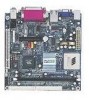
...size of the company's open industry-wide total connectivity initiative. The mainboard comes with an embedded VIA Processor, boasting ultra low power consumption and cool, quiet operation. This chapter includes the following sections: Mainboard Specifications 1-2 Mainboard Layout 1-4 Back Panel Ports 1-5 Slots 1-5 Connectors / Jumpers 1-6 1-1 as part of FlexATX mainboard form factor. Chapter 1 Specifications The ultra-compact and highly intergrated VIA EPIA-M Mini-ITX Mainboard is the smallest form factor mainboard specification available today, developed by VIA Technologies...
...size of the company's open industry-wide total connectivity initiative. The mainboard comes with an embedded VIA Processor, boasting ultra low power consumption and cool, quiet operation. This chapter includes the following sections: Mainboard Specifications 1-2 Mainboard Layout 1-4 Back Panel Ports 1-5 Slots 1-5 Connectors / Jumpers 1-6 1-1 as part of FlexATX mainboard form factor. Chapter 1 Specifications The ultra-compact and highly intergrated VIA EPIA-M Mini-ITX Mainboard is the smallest form factor mainboard specification available today, developed by VIA Technologies...

User Manual
Page 10
can be switched to 6 channel output with Smart 5.1 (See Appendix A) BIOS • AwardBIOS with 2 / 4Mbit flash memory Form Factor • 17 cm X 17 cm Mini-ITX (4 layers) 1-3 Specifications Onboard I/O Connectors • Two 1394 connectors for two 1394 ports • Front-panel audio connectors (Mic and Line Out) • CD Audio-in connector • 1 FIR connector; 1 PS2 connector • Wake-on-LAN • CPU / System Fan / FAN3 • 1 I2C connector • 1 Connector for LVDS module (Optional) • Serial port connector for second...
can be switched to 6 channel output with Smart 5.1 (See Appendix A) BIOS • AwardBIOS with 2 / 4Mbit flash memory Form Factor • 17 cm X 17 cm Mini-ITX (4 layers) 1-3 Specifications Onboard I/O Connectors • Two 1394 connectors for two 1394 ports • Front-panel audio connectors (Mic and Line Out) • CD Audio-in connector • 1 FIR connector; 1 PS2 connector • Wake-on-LAN • CPU / System Fan / FAN3 • 1 I2C connector • 1 Connector for LVDS module (Optional) • Serial port connector for second...

User Manual
Page 12
Back Panel Ports Port Audio Jacks COM 1 LPT1 PS2-MS PS2-KB RCA_JACK RJ45 S-VIDEO USB 1-2 VGA Out Description Line-Out, Line-In, Microphone Serial port Parallel port PS2 mouse port PS2 keyboard port RCA Video or SPDIF jack 10/100 NIC port S-Video Port Universal Serial Bus ports 1 - 2 VGA out port Slots Slot DIMM PCI Description Memory module slot Expansion card slot Specifications Page 2-10 2-10 2-9 2-7 2-7 2-8 2-8 2-8 2-8 2-8 Page 2-4 2-20 1-5
Back Panel Ports Port Audio Jacks COM 1 LPT1 PS2-MS PS2-KB RCA_JACK RJ45 S-VIDEO USB 1-2 VGA Out Description Line-Out, Line-In, Microphone Serial port Parallel port PS2 mouse port PS2 keyboard port RCA Video or SPDIF jack 10/100 NIC port S-Video Port Universal Serial Bus ports 1 - 2 VGA out port Slots Slot DIMM PCI Description Memory module slot Expansion card slot Specifications Page 2-10 2-10 2-9 2-7 2-7 2-8 2-8 2-8 2-8 2-8 Page 2-4 2-20 1-5

User Manual
Page 13
... F_AUDIO F_PANEL Fans FDD FIR I2C IDE 1-2 LVDS SPDIF_SEL USB 3/4 WOL Description Connector for first 1394 port Connector for second 1394 port ATX power cable connector Onboard CD audio cable connector Consumer IR connector Jumper to reset CMOS settings to default Second serial port connector Connectors for optional front audio panel Case connectors CPU, System, Fan3 Floppy disk drive connector Fast Infrared Radiation connector I2C connector IDE hard disk drive connectors LVDS connector Sony Philips Digital Interface jumper Universal Serial Bus connectors 3 - 4 Wake On LAN connector Page 2-15...
... F_AUDIO F_PANEL Fans FDD FIR I2C IDE 1-2 LVDS SPDIF_SEL USB 3/4 WOL Description Connector for first 1394 port Connector for second 1394 port ATX power cable connector Onboard CD audio cable connector Consumer IR connector Jumper to reset CMOS settings to default Second serial port connector Connectors for optional front audio panel Case connectors CPU, System, Fan3 Floppy disk drive connector Fast Infrared Radiation connector I2C connector IDE hard disk drive connectors LVDS connector Sony Philips Digital Interface jumper Universal Serial Bus connectors 3 - 4 Wake On LAN connector Page 2-15...
User Manual
Page 17
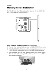
Chapter 2 Memory Module Installation The VIA EPIA-M Mini-ITX Mainboard provides one 184-pin DIMM slot for DDR266 SDRAM memory modules. With both hands, press the DDR SDRAM module down into the DIMM slot so that the white retaining latches rotate up and secure the module in the correct position. 3. Align the DDR SDRAM module with the corresponding notches on the DIMM slot. The modules will only fit if placed in place (see picture below). 2-4 DDR SDRAM Module Installation Procedures 1. Push the white retaining latches at either end of the DIMM slot outwards. 2.
Chapter 2 Memory Module Installation The VIA EPIA-M Mini-ITX Mainboard provides one 184-pin DIMM slot for DDR266 SDRAM memory modules. With both hands, press the DDR SDRAM module down into the DIMM slot so that the white retaining latches rotate up and secure the module in the correct position. 3. Align the DDR SDRAM module with the corresponding notches on the DIMM slot. The modules will only fit if placed in place (see picture below). 2-4 DDR SDRAM Module Installation Procedures 1. Push the white retaining latches at either end of the DIMM slot outwards. 2.

User Manual
Page 23
... / Subwoofer The Line-Out jack is for connecting to external speakers or headphones. 2-Channel 6-Channel The Line-In jack is for connecting to a microphone. Please note that Windows 98 only supports 4-channel audio. 2-10 Rear (L/R) Front (L/R) Center/Sub When 6-channel applications are used, all three jacks become output connectors with Smart 5.1 (See Appendix A) In order for connecting to function, the operating system and multimedia...
... / Subwoofer The Line-Out jack is for connecting to external speakers or headphones. 2-Channel 6-Channel The Line-In jack is for connecting to a microphone. Please note that Windows 98 only supports 4-channel audio. 2-10 Rear (L/R) Front (L/R) Center/Sub When 6-channel applications are used, all three jacks become output connectors with Smart 5.1 (See Appendix A) In order for connecting to function, the operating system and multimedia...

User Manual
Page 27
... function of ACPI WOL may be disabled when users unplug the power cord or turn off the power button manually. WOL 2-14 Please plug the USB 2-port module onto this pinheader. Pin Signal 1 VCC 3 USB2 5 USB2 + 7 GND 9 NC Pin Signal 2 VCC 4 USB 3 6 USB 3 + 8 GND 10 GND 2 10 1 9 USB 3/4 Wake-on LAN: WOL This connector allows you to 2 additional USB ports. The connector will power up to connect a network card with the Wake-On LAN function. Chapter 2 USB pin-header: USB3/4 The mainboard provides 1 front USB pin-header connector, allowing...
... function of ACPI WOL may be disabled when users unplug the power cord or turn off the power button manually. WOL 2-14 Please plug the USB 2-port module onto this pinheader. Pin Signal 1 VCC 3 USB2 5 USB2 + 7 GND 9 NC Pin Signal 2 VCC 4 USB 3 6 USB 3 + 8 GND 10 GND 2 10 1 9 USB 3/4 Wake-on LAN: WOL This connector allows you to 2 additional USB ports. The connector will power up to connect a network card with the Wake-On LAN function. Chapter 2 USB pin-header: USB3/4 The mainboard provides 1 front USB pin-header connector, allowing...
User Manual
Page 33
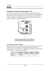
... A# 2-20 Meanwhile, read the documentation for the expansion card to make sure that you to insert PCI expansion card. PCI Interrupt Request Routing The IRQ, abbreviation of interrupt request line and pronounced I-R-Q, are typically connected to the microprocessor. The "PCI & LAN" IRQ pins are hardware lines over which devices can send interrupt signals to the PCI bus INT A# ~ INT D# pins as jumpers, switches or BIOS configuration.
... A# 2-20 Meanwhile, read the documentation for the expansion card to make sure that you to insert PCI expansion card. PCI Interrupt Request Routing The IRQ, abbreviation of interrupt request line and pronounced I-R-Q, are typically connected to the microprocessor. The "PCI & LAN" IRQ pins are hardware lines over which devices can send interrupt signals to the PCI bus INT A# ~ INT D# pins as jumpers, switches or BIOS configuration.

User Manual
Page 40
... Zone Sector PIO Mode Ultra DMA Mode The name of this category. The settings are None, Auto, Manual. The settings are Disabled and Auto. 3-7 Select Auto whenever possible. The settings are Mode 0/1/2/3/4, Auto. Number of heads. The hard disk will match the name of the menu. BIOS Setup IDE Primary Master/Slave, Secondary Master/Slave Press Enter to enter the sub-menu and the following screen appears: The specifications of your hard disk vendor or...
... Zone Sector PIO Mode Ultra DMA Mode The name of this category. The settings are None, Auto, Manual. The settings are Disabled and Auto. 3-7 Select Auto whenever possible. The settings are Mode 0/1/2/3/4, Auto. Number of heads. The hard disk will match the name of the menu. BIOS Setup IDE Primary Master/Slave, Secondary Master/Slave Press Enter to enter the sub-menu and the following screen appears: The specifications of your hard disk vendor or...
User Manual
Page 41
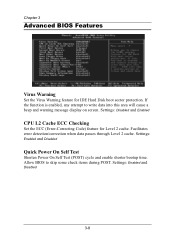
Settings: Disabled and Enabled CPU L2 Cache ECC Checking Set the ECC (Error-Correcting Code) feature for IDE Hard Disk boot sector protection. If the function is enabled, any attempt to skip some check items during POST. Settings: Enabled and Disabled 3-8 Settings: Enabled and Disabled Quick Power On Self Test Shorten Power On Self Test (POST) cycle and enable shorter bootup time. Facilitates error detection/correction when data passes through Level 2 cache. Chapter 3 Advanced BIOS Features...
Settings: Disabled and Enabled CPU L2 Cache ECC Checking Set the ECC (Error-Correcting Code) feature for IDE Hard Disk boot sector protection. If the function is enabled, any attempt to skip some check items during POST. Settings: Enabled and Disabled 3-8 Settings: Enabled and Disabled Quick Power On Self Test Shorten Power On Self Test (POST) cycle and enable shorter bootup time. Facilitates error detection/correction when data passes through Level 2 cache. Chapter 3 Advanced BIOS Features...

User Manual
Page 42
... fails to load the disk operating system. The system will boot from network drive. The system will boot from USB CDROM. The system will boot from first HDD. The system will boot from LS-120 drive. Settings: Enabled and Disabled 3-9 The system will boot from USB HDD. The system will boot from fourth HDD. Disable this sequence. The system will boot from ATAPI ZIP drive. Settings: Enabled and Disabled Boot Up Floppy Seek Set floppy seek during POST, BIOS will determine...
... fails to load the disk operating system. The system will boot from network drive. The system will boot from USB CDROM. The system will boot from first HDD. The system will boot from LS-120 drive. Settings: Enabled and Disabled 3-9 The system will boot from USB HDD. The system will boot from fourth HDD. Disable this sequence. The system will boot from ATAPI ZIP drive. Settings: Enabled and Disabled Boot Up Floppy Seek Set floppy seek during POST, BIOS will determine...

User Manual
Page 43
... 1000 Security Option If you have set the rate (characters/second) at which the keys are described below: Setup The password prompt appears only when end users try to set a password, select whether the password is powered on or when end users try to run Setup. Settings: Enabled and Disabled 3-10 System A password prompt appears every time when the computer is enabled, this item allows you enter Setup. Settings: On...
... 1000 Security Option If you have set the rate (characters/second) at which the keys are described below: Setup The password prompt appears only when end users try to set a password, select whether the password is powered on or when end users try to run Setup. Settings: Enabled and Disabled 3-10 System A password prompt appears every time when the computer is enabled, this item allows you enter Setup. Settings: On...

User Manual
Page 45
... more data. Settings: Enabled and Disabled 3-12 AGP Aperture Size This setting controls how much memory space can write up to four words of the PCI memory address range dedicated to graphics memory address space. Settings: 4MB, 8MB, 16MB, 32MB, 64MB, 128MB, and 256MB AGP Mode (Internal) This mainboard supports the AGP 4x interface. The aperture is used for optimizing the chipset functions. CPU to PCI POST Write When Enabled, CPU can be...
... more data. Settings: Enabled and Disabled 3-12 AGP Aperture Size This setting controls how much memory space can write up to four words of the PCI memory address range dedicated to graphics memory address space. Settings: 4MB, 8MB, 16MB, 32MB, 64MB, 128MB, and 256MB AGP Mode (Internal) This mainboard supports the AGP 4x interface. The aperture is used for optimizing the chipset functions. CPU to PCI POST Write When Enabled, CPU can be...

User Manual
Page 47
... mode; Settings: PCI Slot and AGP Frame Buffer Size This setting instructs the BIOS to and from the hard disk drive. Choose Enabled to use standard mode. Settings: Enabled and Disabled Display Card Priority This setting specifies which VGA card is also called block transfer, multiple commands or multiple sector read/write. Settings: 16M, 32M, 64M 3-14 Enabled enables IDE controller to use the fast block mode to transfer data to reserved the specified amount of memory for two IDE channels. Settings: Enabled and Disabled IDE...
... mode; Settings: PCI Slot and AGP Frame Buffer Size This setting instructs the BIOS to and from the hard disk drive. Choose Enabled to use standard mode. Settings: Enabled and Disabled Display Card Priority This setting specifies which VGA card is also called block transfer, multiple commands or multiple sector read/write. Settings: 16M, 32M, 64M 3-14 Enabled enables IDE controller to use the fast block mode to transfer data to reserved the specified amount of memory for two IDE channels. Settings: Enabled and Disabled IDE...
User Manual
Page 48
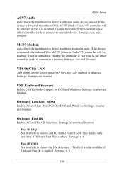
... VIA OnChip LAN enabled or disabled. Settings: Enabled and Disabled Onboard Lan Boot ROM Enable Onboard Lan Boot ROM for DOS and Windows. Settings: Auto and Disabled MC97 Modem Auto allows the mainboard to detect whether an audio device is used . This field is only available if Onboard Fast IR is detected, the onboard VIA AC'97 (Audio Codec'97) controller will be enabled; BIOS Setup AC97 Audio Auto allows the mainboard to detect whether a modem is used . Settings: Auto and Disabled VIA OnChip LAN This setting allows you want to use other controller cards to connect...
... VIA OnChip LAN enabled or disabled. Settings: Enabled and Disabled Onboard Lan Boot ROM Enable Onboard Lan Boot ROM for DOS and Windows. Settings: Auto and Disabled MC97 Modem Auto allows the mainboard to detect whether an audio device is used . This field is only available if Onboard Fast IR is detected, the onboard VIA AC'97 (Audio Codec'97) controller will be enabled; BIOS Setup AC97 Audio Auto allows the mainboard to detect whether a modem is used . Settings: Auto and Disabled VIA OnChip LAN This setting allows you want to use other controller cards to connect...

User Manual
Page 49
... onboard serial port A/serial port B. To operate the onboard parallel port in ECP mode. Choosing ECP + EPP will operate in the EPP mode, choose EPP. Settings: Disabled, 378/IRQ7, 278/IRQ5, 3BC/IRQ7 Parallel Port Mode Set the parallel port mode. Select Enabled when you have installed a floppy disk drive. Chapter 3 SuperIO Device Press Enter to automatically determine the correct base I/O port address. Selecting Auto allows BIOS to enter the sub-menu and the following screen appears: Onboard FDC Controller Enable the onboard floppy controller...
... onboard serial port A/serial port B. To operate the onboard parallel port in ECP mode. Choosing ECP + EPP will operate in the EPP mode, choose EPP. Settings: Disabled, 378/IRQ7, 278/IRQ5, 3BC/IRQ7 Parallel Port Mode Set the parallel port mode. Select Enabled when you have installed a floppy disk drive. Chapter 3 SuperIO Device Press Enter to automatically determine the correct base I/O port address. Selecting Auto allows BIOS to enter the sub-menu and the following screen appears: Onboard FDC Controller Enable the onboard floppy controller...

User Manual
Page 56
... any changes to Yes, BIOS will automatically assign IRQ, DMA and memory base address fields. Choose Auto(ESCD) if unsure, the BIOS will only initialize the PnP cards used for booting (VGA, IDE, SCSI). Set to No, BIOS will be initialized by the PnP operating system like Windows® 95 or 98/98SE. Settings: Auto (ESCD) and Manual 3-23 Settings: Enabled and Disabled Resource Controlled By The BIOS can not boot. PNP/PCI Configurations BIOS Setup...
... any changes to Yes, BIOS will automatically assign IRQ, DMA and memory base address fields. Choose Auto(ESCD) if unsure, the BIOS will only initialize the PnP cards used for booting (VGA, IDE, SCSI). Set to No, BIOS will be initialized by the PnP operating system like Windows® 95 or 98/98SE. Settings: Auto (ESCD) and Manual 3-23 Settings: Enabled and Disabled Resource Controlled By The BIOS can not boot. PNP/PCI Configurations BIOS Setup...

User Manual
Page 71
... Hard Disk Drives and ensures IDE device compatibility), AGP VxD Driver (provides service routines to your VGA driver and interface directly to hardware, providing fast graphical access), IRQ Routing Miniport Driver (sets the system's PCI IRQ routing sequence) and VIA INF Driver (enables the VIA Power Management function). • VIA Graphics Driver: Enhance the onboard VIA graphic chip. • VIA Audio Driver: Enhance the onboard VIA audio chip. • VIA USB 2.0 Driver: Enhance VIA USB 2.0 ports. • VIA LAN Driver: Enhance the onboard VIA LAN chip. • VIA FIR Driver: Support...
... Hard Disk Drives and ensures IDE device compatibility), AGP VxD Driver (provides service routines to your VGA driver and interface directly to hardware, providing fast graphical access), IRQ Routing Miniport Driver (sets the system's PCI IRQ routing sequence) and VIA INF Driver (enables the VIA Power Management function). • VIA Graphics Driver: Enhance the onboard VIA graphic chip. • VIA Audio Driver: Enhance the onboard VIA audio chip. • VIA USB 2.0 Driver: Enhance VIA USB 2.0 ports. • VIA LAN Driver: Enhance the onboard VIA LAN chip. • VIA FIR Driver: Support...
