Specifications
Page 1
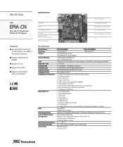
...x Front panel connector 1 x Front panel audio connector for Line-out and Mic-in 2 x Fan connectors for CPU and system fans 1 x ATX power connector 1 x PS2 mouse port 1 x PS2 keyboard port 1 x VGA port 1 x Serial port 1 x GigaLAN port 4 x USB 2.0 ports 1 x RCA port (S/PDIF or TV-out) 1 x S-Video port 3 x Audio jacks: Line-out, Line-in and Mic-in (Horizontal, Smart 5.1 support) Award BIOS 4/8Mbit flash memory Windows XP, Windows Embedded CE, Windows Embedded Standard, Linux CPU voltage monitoring Wake-on LAN, Keyboard Power-on, Timer Power-on System power management AC power failure recovery...
...x Front panel connector 1 x Front panel audio connector for Line-out and Mic-in 2 x Fan connectors for CPU and system fans 1 x ATX power connector 1 x PS2 mouse port 1 x PS2 keyboard port 1 x VGA port 1 x Serial port 1 x GigaLAN port 4 x USB 2.0 ports 1 x RCA port (S/PDIF or TV-out) 1 x S-Video port 3 x Audio jacks: Line-out, Line-in and Mic-in (Horizontal, Smart 5.1 support) Award BIOS 4/8Mbit flash memory Windows XP, Windows Embedded CE, Windows Embedded Standard, Linux CPU voltage monitoring Wake-on LAN, Keyboard Power-on, Timer Power-on System power management AC power failure recovery...
Specifications
Page 2
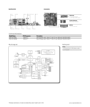
.../133 IDE ribbon cable 1 x I /F LCD CONNECTOR (PIN HEADER) VIA C7 CPU ATX POWER CONNECTOR +12 VCORE CONN VIA NORTH BRIDGE CN700 DDR2 SDRAM DIMM x1 SATA BUS IDE BUS MII ICS CLOCK SYNT HESIZER ICS9 53002 ICS CLOCK BUFFER ICS9 P956 CIR CONN PCI BUS PCI SLOT x1 (Suppor t 2 PCI Devices with Riser Card) V- Update: June 27, 2012. www.viaembedded.com Back Panel I/O Accessories PS/2 COM1 mouse RJ-45 RCA/ Line-out Mic-in SPDIF PS/2 keyboard VGA-out USB S-Video...
.../133 IDE ribbon cable 1 x I /F LCD CONNECTOR (PIN HEADER) VIA C7 CPU ATX POWER CONNECTOR +12 VCORE CONN VIA NORTH BRIDGE CN700 DDR2 SDRAM DIMM x1 SATA BUS IDE BUS MII ICS CLOCK SYNT HESIZER ICS9 53002 ICS CLOCK BUFFER ICS9 P956 CIR CONN PCI BUS PCI SLOT x1 (Suppor t 2 PCI Devices with Riser Card) V- Update: June 27, 2012. www.viaembedded.com Back Panel I/O Accessories PS/2 COM1 mouse RJ-45 RCA/ Line-out Mic-in SPDIF PS/2 keyboard VGA-out USB S-Video...

User Manual
Page 3
... before connecting the equipment to force open the battery. Do not discard used batteries according to local regulations. Lay this product. DO NOT COVER THE OPENINGS. 6. All cautions and warnings on it up. 5. Keep this User's Manual for future reference. 3. Do not place anything over the power cord. 8. Do not attempt to the power inlet. 7. Make sure the voltage...
... before connecting the equipment to force open the battery. Do not discard used batteries according to local regulations. Lay this product. DO NOT COVER THE OPENINGS. 6. All cautions and warnings on it up. 5. Keep this User's Manual for future reference. 3. Do not place anything over the power cord. 8. Do not attempt to the power inlet. 7. Make sure the voltage...

User Manual
Page 6
... Mainboard Specifications 2 Mainboard Layout 4 Back Panel Layout 5 Back Panel Ports 6 Slots 6 Onboard Connectors 7 Onboard Jumpers 7 Chapter 2 8 Installation 8 CPU 9 Memory Module Installation 11 Connecting the Power Supply 12 Back Panel Ports 13 Connectors 16 Jumpers 21 Slots 22 Chapter 3 23 BIOS Setup 23 Entering Setup 24 Control Keys 25 Navigating the BIOS Menus 26 Getting Help 27 Main Menu 28 Standard CMOS Features 30 IDE Drives 31 Advanced BIOS Features 32 Hard Disk Boot Priority 35 Advanced Chipset Features 36 AGP & P2P Bridge Control 38 CPU & PCI Bus Control...
... Mainboard Specifications 2 Mainboard Layout 4 Back Panel Layout 5 Back Panel Ports 6 Slots 6 Onboard Connectors 7 Onboard Jumpers 7 Chapter 2 8 Installation 8 CPU 9 Memory Module Installation 11 Connecting the Power Supply 12 Back Panel Ports 13 Connectors 16 Jumpers 21 Slots 22 Chapter 3 23 BIOS Setup 23 Entering Setup 24 Control Keys 25 Navigating the BIOS Menus 26 Getting Help 27 Main Menu 28 Standard CMOS Features 30 IDE Drives 31 Advanced BIOS Features 32 Hard Disk Boot Priority 35 Advanced Chipset Features 36 AGP & P2P Bridge Control 38 CPU & PCI Bus Control...

User Manual
Page 7
TV Output Connector 41 Integrated Peripherals 42 Power Management Setup 44 Peripheral Activities 47 IRQs Activities 50 PNP/PCI Configurations 51 IRQ Resources 53 PC Health Status 54 Frequency / Voltage Control 55 Load Fail-Safe Defaults 59 Load Optimized Defaults 60 Set Supervisor / User Password 61 Save & Exit Setup 63 Exit Without Saving 64 Chapter 4 65 Driver Installation 65 Microsoft Driver Support 66 Linux Driver Support 66 iii
TV Output Connector 41 Integrated Peripherals 42 Power Management Setup 44 Peripheral Activities 47 IRQs Activities 50 PNP/PCI Configurations 51 IRQ Resources 53 PC Health Status 54 Frequency / Voltage Control 55 Load Fail-Safe Defaults 59 Load Optimized Defaults 60 Set Supervisor / User Password 61 Save & Exit Setup 63 Exit Without Saving 64 Chapter 4 65 Driver Installation 65 Microsoft Driver Support 66 Linux Driver Support 66 iii

User Manual
Page 11
...x S-Video port • 3 x Audio Jacks: line-out, line-in and mic-in (Horizontal, Smart 5.1 Support) Onboard I/O Connectors • 1 x USB pin header for 4 additional USB 2.0 ports • 1 x Front Panel audio pin header (Mic-in and Line-out) • 2 x Serial ATA connectors • 1 x LPT connector • 1 x CD-In pin header • 1 x CIR pin header (Switchable for KB/MS) • 2 x Fan connectors (CPU Fan and System Fan) • 1 x Front-Panel pin header BIOS • • Award BIOS with 4/8Mbit flash memory capacity ACPI2.0, SMBIOS2.1 and DMI2.2 Form Factor • Mini-ITX...
...x S-Video port • 3 x Audio Jacks: line-out, line-in and mic-in (Horizontal, Smart 5.1 Support) Onboard I/O Connectors • 1 x USB pin header for 4 additional USB 2.0 ports • 1 x Front Panel audio pin header (Mic-in and Line-out) • 2 x Serial ATA connectors • 1 x LPT connector • 1 x CD-In pin header • 1 x CIR pin header (Switchable for KB/MS) • 2 x Fan connectors (CPU Fan and System Fan) • 1 x Front-Panel pin header BIOS • • Award BIOS with 4/8Mbit flash memory capacity ACPI2.0, SMBIOS2.1 and DMI2.2 Form Factor • Mini-ITX...

User Manual
Page 14
Chapter 1 BACK PANEL PORTS Port Audio Jacks COM PS/2 Mouse PS/2 Keyboard RCA/SPDIF RJ45 USB VGA S-Video Description 3 Audio ports (line-out, line-in and mic-in) Serial port 1 PS/2 mouse port PS/2 keyboard port RCA port (SPDIF or TV out) RJ45 port USB 2.0 ports VGA port S-Video port SLOTS Port DDR DIMM PCI Description Memory module slot Expansion card slot Page 13-15 13 13 13 13-14 13-14 13-14 13 13-14 Page 11 22 6
Chapter 1 BACK PANEL PORTS Port Audio Jacks COM PS/2 Mouse PS/2 Keyboard RCA/SPDIF RJ45 USB VGA S-Video Description 3 Audio ports (line-out, line-in and mic-in) Serial port 1 PS/2 mouse port PS/2 keyboard port RCA port (SPDIF or TV out) RJ45 port USB 2.0 ports VGA port S-Video port SLOTS Port DDR DIMM PCI Description Memory module slot Expansion card slot Page 13-15 13 13 13 13-14 13-14 13-14 13 13-14 Page 11 22 6

User Manual
Page 15
ONBOARD CONNECTORS Connector ATXPWR CD-In CPUFAN F_AUDIO F_PANEL IDE 1-2 KBMS LPT SATA 1-2 SYSFAN USB 4-7 Description Power cable connector CD-In connector CPU fan connector Front Audio connector Front panel connector IDE drive connectors Keyboard and Mouse connector LPT connector Serial ATA 1 and 2 connectors System fan connector Universal Serial Bus 2.0 connectors 3-4 ONBOARD JUMPERS Jumper CLEAR_CMOS SPDIF_SEL Description Reset CMOS settings S/PDIF selector Specifications Page 12 18 10 19 17 16 19 20 18 10 18 Page 21 21 7
ONBOARD CONNECTORS Connector ATXPWR CD-In CPUFAN F_AUDIO F_PANEL IDE 1-2 KBMS LPT SATA 1-2 SYSFAN USB 4-7 Description Power cable connector CD-In connector CPU fan connector Front Audio connector Front panel connector IDE drive connectors Keyboard and Mouse connector LPT connector Serial ATA 1 and 2 connectors System fan connector Universal Serial Bus 2.0 connectors 3-4 ONBOARD JUMPERS Jumper CLEAR_CMOS SPDIF_SEL Description Reset CMOS settings S/PDIF selector Specifications Page 12 18 10 19 17 16 19 20 18 10 18 Page 21 21 7

User Manual
Page 22
These ports allow connection to the mainboard. 14 S-Video port The black port allows you to connect TV monitor or Svideo device to a Local Area Network (LAN) through a network hub and USB 2.0 devices. USB 2.0 ports These two 4-pin Universal Serial Bus (USB) ports are available for connecting USB 2.0 devices. Chapter 2 RJ45 10/100 LAN and USB Connector The mainboard provides a standard RJ-45 and USB 2.0 ports. RCA / SPDIF jack The yellow jack connects to external composite video device or audio output device.
These ports allow connection to the mainboard. 14 S-Video port The black port allows you to connect TV monitor or Svideo device to a Local Area Network (LAN) through a network hub and USB 2.0 devices. USB 2.0 ports These two 4-pin Universal Serial Bus (USB) ports are available for connecting USB 2.0 devices. Chapter 2 RJ45 10/100 LAN and USB Connector The mainboard provides a standard RJ-45 and USB 2.0 ports. RCA / SPDIF jack The yellow jack connects to external composite video device or audio output device.

User Manual
Page 23
... (Left/Right) Center/Sub-woofer 15 Audio Port: Installation The Line-Out jack is for connecting to the 3-jack connectors on your desktop after installing the audio driver. You can be switched to setup the 6-channel system. After completing the previous installation, connect the speakers to external speakers or headphones. Shown below are the corresponding connections to Smart 5.1 6-channel audio output. Note: The audio ports can enable the function by clicking the "Vinyl...
... (Left/Right) Center/Sub-woofer 15 Audio Port: Installation The Line-Out jack is for connecting to the 3-jack connectors on your desktop after installing the audio driver. You can be switched to setup the 6-channel system. After completing the previous installation, connect the speakers to external speakers or headphones. Shown below are the corresponding connections to Smart 5.1 6-channel audio output. Note: The audio ports can enable the function by clicking the "Vinyl...

User Manual
Page 29
... will cause system boot failure. Clear Setting Clear CMOS setting Keep CMOS setting 1 2 3 OFF ON ON ON ON OFF 123 Keep 123 Caution: Except when clearing the RTC RAM, never remove the cap on pins 2 and 3 while the system is for setting some mainboard functions. SPDIF/COMP Select: SPDIF_SEL This jumper is off. Clear CMOS: CLEAR_CMOS The onboard CMOS RAM stores system configuration data and has an onboard battery power supply. To reset the CMOS settings, set the jumper on CLEAR_CMOS jumper default position.
... will cause system boot failure. Clear Setting Clear CMOS setting Keep CMOS setting 1 2 3 OFF ON ON ON ON OFF 123 Keep 123 Caution: Except when clearing the RTC RAM, never remove the cap on pins 2 and 3 while the system is for setting some mainboard functions. SPDIF/COMP Select: SPDIF_SEL This jumper is off. Clear CMOS: CLEAR_CMOS The onboard CMOS RAM stores system configuration data and has an onboard battery power supply. To reset the CMOS settings, set the jumper on CLEAR_CMOS jumper default position.

User Manual
Page 39
... category. If you enter incorrect information in this match the name of sectors Settings: [0, 1, 2, 3, 4] Settings: [Disabled, Auto] 31 AwardBIOS CMOS Setup Utility IDE Channel 0 Master [Press Enter] Item Help [Auto] [Auto] 0 MB Menu Level To auto-detect the HDD's size, head... channel 0 0 0 0 0 [Auto] [Auto] : Move Enter: Select F5: Previous Values +/-/PU/PD: Value F10: Save F6: Fail-Safe Defaults ESC: Exit F1: General F7: Optimized Defaults Help The specifications of your hard disk vendor or system manufacturer...
... category. If you enter incorrect information in this match the name of sectors Settings: [0, 1, 2, 3, 4] Settings: [Disabled, Auto] 31 AwardBIOS CMOS Setup Utility IDE Channel 0 Master [Press Enter] Item Help [Auto] [Auto] 0 MB Menu Level To auto-detect the HDD's size, head... channel 0 0 0 0 0 [Auto] [Auto] : Move Enter: Select F5: Previous Values +/-/PU/PD: Value F10: Save F6: Fail-Safe Defaults ESC: Exit F1: General F7: Optimized Defaults Help The specifications of your hard disk vendor or system manufacturer...

User Manual
Page 40
...IDE Hard Disk boot sector protection. Chapter 3 ADVANCED BIOS FEATURES Phoenix - AwardBIOS CMOS Setup Utility Advanced BIOS Features Hard Disk Boot Priority Virus Warning CPU L1 & L2 Cache Quick Power On Self Test First Boot Device Second Boot Device Third Boot Device Boot Other Device Boot Up NumLock Status Typematic Rate Setting Typematic Rate (Chars/Sec) Typematic Delay (Msec) Security Option Display Full Screen Logo Display Small Logo [Press Enter] [Disabled] [Enabled] [Enabled] [USB-FDD] [CDROM] [Hard Disk] [Enabled] [On] [Disabled] 6 250 [Setup] [Enabled] [Disabled] Item Help Menu...
...IDE Hard Disk boot sector protection. Chapter 3 ADVANCED BIOS FEATURES Phoenix - AwardBIOS CMOS Setup Utility Advanced BIOS Features Hard Disk Boot Priority Virus Warning CPU L1 & L2 Cache Quick Power On Self Test First Boot Device Second Boot Device Third Boot Device Boot Other Device Boot Up NumLock Status Typematic Rate Setting Typematic Rate (Chars/Sec) Typematic Delay (Msec) Security Option Display Full Screen Logo Display Small Logo [Press Enter] [Disabled] [Enabled] [Enabled] [USB-FDD] [CDROM] [Hard Disk] [Enabled] [On] [Disabled] 6 250 [Setup] [Enabled] [Disabled] Item Help Menu...

User Manual
Page 41
Setting LS120 Hard Disk CD-ROM ZIP100 USB-FDD USB-ZIP USB-CDROM Legacy LAN Disabled Description Boot from LS-120 drive Boot from the HDD Boot from CD-ROM Boot from ATAPI ZIP drive Boot from USB floppy drive Boot from USB ZIP drive Boot from USB CDROM Boot from network drive Disable the boot device sequence Boot Other Device Enables the system to boot from alternate devices if the system fails to load the disk operating system. Setting Enabled Disabled Description Enable alternate boot device No alternate boot device allowed Boot Up NumLock Status Set the NumLock status when...
Setting LS120 Hard Disk CD-ROM ZIP100 USB-FDD USB-ZIP USB-CDROM Legacy LAN Disabled Description Boot from LS-120 drive Boot from the HDD Boot from CD-ROM Boot from ATAPI ZIP drive Boot from USB floppy drive Boot from USB ZIP drive Boot from USB CDROM Boot from network drive Disable the boot device sequence Boot Other Device Enables the system to boot from alternate devices if the system fails to load the disk operating system. Setting Enabled Disabled Description Enable alternate boot device No alternate boot device allowed Boot Up NumLock Status Set the NumLock status when...

User Manual
Page 42
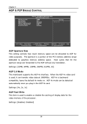
... end users try to run BIOS Setup Display Full Screen Logo Show full screen logo during BIOS boot up process. Settings: [Enabled, Disabled] Display Small Logo Show small energy star logo during BIOS boot up process. Settings: [Enabled, Disabled] 34 Settings: [6, 8, 10, 12, 15, 20, 24, 30] Typematic Delay (Msec) This item sets the delay between when the key was first pressed and when the system begins to run BIOS Setup Password prompt...
... end users try to run BIOS Setup Display Full Screen Logo Show full screen logo during BIOS boot up process. Settings: [Enabled, Disabled] Display Small Logo Show small energy star logo during BIOS boot up process. Settings: [Enabled, Disabled] 34 Settings: [6, 8, 10, 12, 15, 20, 24, 30] Typematic Delay (Msec) This item sets the delay between when the key was first pressed and when the system begins to run BIOS Setup Password prompt...
User Manual
Page 46
Settings: [Enabled, Disabled] 38 Host cycles that hit the aperture range are forwarded to graphics memory address space. AGP 4x is used , it can transfer video data at 1066MB/s. AGP 4x mode can be detected automatically once you plug in the AGP 4x card. AwardBIOS CMOS Setup Utility AGP & P2P Bridge Control AGP Aperture Size AGP 2.0 Mode AGP Fast Write AGP 3.0 Calibration cycle VGA Share Memory Size Direct Frame Buffer...
Settings: [Enabled, Disabled] 38 Host cycles that hit the aperture range are forwarded to graphics memory address space. AGP 4x is used , it can transfer video data at 1066MB/s. AGP 4x mode can be detected automatically once you plug in the AGP 4x card. AwardBIOS CMOS Setup Utility AGP & P2P Bridge Control AGP Aperture Size AGP 2.0 Mode AGP Fast Write AGP 3.0 Calibration cycle VGA Share Memory Size Direct Frame Buffer...

User Manual
Page 50
... - AwardBIOS CMOS Setup Utility Integrated Peripherals [Press Enter] Item Help Onboard IDE Channel 1 Onboard IDE Channel 2 IDE Prefetch Mode IDE HDD Block Mode OnChip SATA SATA Mode [Enabled] [Enabled] [Enabled] [Enabled] [Enabled] [RAID] Menu Level AC97 Audio VIA OnChip LAN Onboard Lan Boot ROM [Auto] [Enabled] [Disabled] OnChip USB Controller OnChip EHCI Controller USB Emulation [All Enabled] [Enabled] [On] : Move Enter: Select F5: Previous Values +/-/PU/PD: Value F10: Save F6: Fail-Safe Defaults ESC: Exit F1: General F7: Optimized Defaults Help Onboard IDE Channel 1 and...
... - AwardBIOS CMOS Setup Utility Integrated Peripherals [Press Enter] Item Help Onboard IDE Channel 1 Onboard IDE Channel 2 IDE Prefetch Mode IDE HDD Block Mode OnChip SATA SATA Mode [Enabled] [Enabled] [Enabled] [Enabled] [Enabled] [RAID] Menu Level AC97 Audio VIA OnChip LAN Onboard Lan Boot ROM [Auto] [Enabled] [Disabled] OnChip USB Controller OnChip EHCI Controller USB Emulation [All Enabled] [Enabled] [On] : Move Enter: Select F5: Previous Values +/-/PU/PD: Value F10: Save F6: Fail-Safe Defaults ESC: Exit F1: General F7: Optimized Defaults Help Onboard IDE Channel 1 and...

User Manual
Page 51
... Disable the controller if another controller card is detected, the onboard VIA AC'97 (Audio Codec'97) controller will be enabled; When set to an audio device. Setting IDE RAID Description Supports two SATA plus two PATA hard disk drives Only SATA supports RAID AC'97 Audio Auto allows the mainboard to detect whether an audio device is the latest generation of up to "ON", support USB legacy keyboard, mouse and storage. BIOS Setup SATA Mode Serial ATA is used to connect to "KB/MS", support USB legacy keyboard and mouse, no support USB storage. And set to...
... Disable the controller if another controller card is detected, the onboard VIA AC'97 (Audio Codec'97) controller will be enabled; When set to an audio device. Setting IDE RAID Description Supports two SATA plus two PATA hard disk drives Only SATA supports RAID AC'97 Audio Auto allows the mainboard to detect whether an audio device is the latest generation of up to "ON", support USB legacy keyboard, mouse and storage. BIOS Setup SATA Mode Serial ATA is used to connect to "KB/MS", support USB legacy keyboard and mouse, no support USB storage. And set to...

User Manual
Page 56
Such PCI cards include LAN card, onboard LAN controller, onboard USB ports, etc. Settings: [Disabled, Enabled] 48 Settings: [Off, On] PCI Master Event Enables the power management unit to monitor hard disk activities. Settings: [Off, On] COM Event Decide whether or not the power management unit should monitor serial port (COM) activities. Settings: [None, COM] HDD Event Enables the power management unit to monitor PCI master activities. Settings: [Disabled, Enabled] Modem Ring Resume Enables any PCI card to monitor VGA activities. Chapter 3 USB Resume from S3 Enables activity...
Such PCI cards include LAN card, onboard LAN controller, onboard USB ports, etc. Settings: [Disabled, Enabled] 48 Settings: [Off, On] PCI Master Event Enables the power management unit to monitor hard disk activities. Settings: [Off, On] COM Event Decide whether or not the power management unit should monitor serial port (COM) activities. Settings: [None, COM] HDD Event Enables the power management unit to monitor PCI master activities. Settings: [Disabled, Enabled] Modem Ring Resume Enables any PCI card to monitor VGA activities. Chapter 3 USB Resume from S3 Enables activity...

User Manual
Page 74
... related drivers can be downloaded from the Advanced Linux Sound Architecture project for integrated audio) For OEM clients and system integrators developing a product for long term production, other code and resources may also be found in the VIA Embedded website at www.viaembedded.com. Chapter 4 MICROSOFT DRIVER SUPPORT The VIA EPIA-CN mainboard is highly compatible with Microsoft operating systems. The latest Windows drivers can be...
... related drivers can be downloaded from the Advanced Linux Sound Architecture project for integrated audio) For OEM clients and system integrators developing a product for long term production, other code and resources may also be found in the VIA Embedded website at www.viaembedded.com. Chapter 4 MICROSOFT DRIVER SUPPORT The VIA EPIA-CN mainboard is highly compatible with Microsoft operating systems. The latest Windows drivers can be...
