English Owners Manual
Page 3
Contents Unpacking 2 Features 2 Installing the QT 206 3 Transducer Wiring 4 Power Cable Wiring 4 Installing The Transducer 5 Transom Mount Transducers 5 Through-the-hull Transducers 8 Low Profile Transducers 9 Stem-type (power Boat Bronze) Transducers 10 Inside-the-hull Transducers 12 Understanding Sonar 14 Air Echoes 14 Setting The Shallow Water Alarm 15 Shallow Water Sensitivity 16 When to Use Less Sensitivity 17 When to Use More Sensitivity 18 Troubleshooting Guideline 19 Features, Specifications, and availability of Optional Accessories are all subject to change without ...
Contents Unpacking 2 Features 2 Installing the QT 206 3 Transducer Wiring 4 Power Cable Wiring 4 Installing The Transducer 5 Transom Mount Transducers 5 Through-the-hull Transducers 8 Low Profile Transducers 9 Stem-type (power Boat Bronze) Transducers 10 Inside-the-hull Transducers 12 Understanding Sonar 14 Air Echoes 14 Setting The Shallow Water Alarm 15 Shallow Water Sensitivity 16 When to Use Less Sensitivity 17 When to Use More Sensitivity 18 Troubleshooting Guideline 19 Features, Specifications, and availability of Optional Accessories are all subject to change without ...
English Owners Manual
Page 4
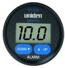
Depth readings are in 1/10 foot increments from 2.5 feet to a maximum depth of 199 feet. n Night Viewing - These readings are shown as whole numbers up to 199 feet. The QT-206 is back lit at all times with 3 lugs attached • Power Cable (attached to the gauge) • Mounting Bracket and hardware • This Operating Guide If any items are missing or damaged, please contact your night time navigational needs. 2 The QT-206 is designed to give depth readings from 2.0 feet to 15 feet, and are displayed on a large Liquid Crystal Display (LCD). UNPACKING Your QT-206 ...
Depth readings are in 1/10 foot increments from 2.5 feet to a maximum depth of 199 feet. n Night Viewing - These readings are shown as whole numbers up to 199 feet. The QT-206 is back lit at all times with 3 lugs attached • Power Cable (attached to the gauge) • Mounting Bracket and hardware • This Operating Guide If any items are missing or damaged, please contact your night time navigational needs. 2 The QT-206 is designed to give depth readings from 2.0 feet to 15 feet, and are displayed on a large Liquid Crystal Display (LCD). UNPACKING Your QT-206 ...
English Owners Manual
Page 5
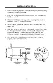
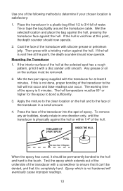
After finding the right location for any adjustments with your dash panel which could be cut out the 2-inch hole. 4. Extending out of the back of the instrument is firmly against the back of the instrument to be damaged. Then tighten securely. 1/2" BRASS STUD P/N: 210-005 2 3/8" 2" 2 1/2" NUT P/N: 3203-009 MOUNTING BRACKET WASHER P/N: 950-025 P/N: 308-029 X-ducer Red Black Shield Alarm More Less Shallow Sensitivity Power + 3 Test fit the unit in the hole, and make any cables or wiring which will provide clear viewing and access to the LCD window. 2. Look at the ...
After finding the right location for any adjustments with your dash panel which could be cut out the 2-inch hole. 4. Extending out of the back of the instrument is firmly against the back of the instrument to be damaged. Then tighten securely. 1/2" BRASS STUD P/N: 210-005 2 3/8" 2" 2 1/2" NUT P/N: 3203-009 MOUNTING BRACKET WASHER P/N: 950-025 P/N: 308-029 X-ducer Red Black Shield Alarm More Less Shallow Sensitivity Power + 3 Test fit the unit in the hole, and make any cables or wiring which will provide clear viewing and access to the LCD window. 2. Look at the ...
English Owners Manual
Page 6
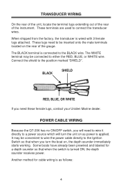
... male terminals located on , the depth sounder immediately starts working. BLACK SHIELD RED, BLUE, OR WHITE If you will need these female lugs, contact your Uniden Marine dealer. It may be convenient to wire the power cable directly to a power source which will turn the boat on the rear of the...
... male terminals located on , the depth sounder immediately starts working. BLACK SHIELD RED, BLUE, OR WHITE If you will need these female lugs, contact your Uniden Marine dealer. It may be convenient to wire the power cable directly to a power source which will turn the boat on the rear of the...
English Owners Manual
Page 7
Connect the BLACK wire to the positive (+) battery terminal. 4. Often called "Shoot Through Transducer"; it is rotating downwards. This is blown, replace with your battery fully charged. Connect the RED wire to the negative (-) battery terminal. 3. You will ensure minimum potential aeration over the acoustic window of the boat, which will want to keep your unit. INSTALLING THE TRANSDUCER The three most popular transducer styles are followed carefully. TRANSOM MOUNT TRANSDUCERS Selecting An Installation Location Mount the transducer fairly close to a 12-volt battery ...
Connect the BLACK wire to the positive (+) battery terminal. 4. Often called "Shoot Through Transducer"; it is rotating downwards. This is blown, replace with your battery fully charged. Connect the RED wire to the negative (-) battery terminal. 3. You will ensure minimum potential aeration over the acoustic window of the boat, which will want to keep your unit. INSTALLING THE TRANSDUCER The three most popular transducer styles are followed carefully. TRANSOM MOUNT TRANSDUCERS Selecting An Installation Location Mount the transducer fairly close to a 12-volt battery ...
English Owners Manual
Page 8
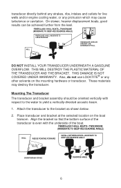
These materials may cause turbulence or cavitation. Mounting The Transducer The transducer and bracket assembly should be achieved further from the keel. Place transducer and bracket at the selected location on the mounting hardware or transducer. Align the bracket so that the bottom surface of the boat. FIBERGLASS V-HULL BOATS-TWIN ENGINE (MODERATE TO DEEP-VEE DEADRISE ANGLE) HULL WEDGE POINTING FORWARD INSTALL BETWEEN DRIVES-MODERATE TO DEEP-VEE DEADRISE ANGLE (Install between drives) DEADRISE ANGLE 6 THIS DAMAGE IS NOT COVERED UNDER WARRANTY. DO NOT INSTALL YOUR ...
These materials may cause turbulence or cavitation. Mounting The Transducer The transducer and bracket assembly should be achieved further from the keel. Place transducer and bracket at the selected location on the mounting hardware or transducer. Align the bracket so that the bottom surface of the boat. FIBERGLASS V-HULL BOATS-TWIN ENGINE (MODERATE TO DEEP-VEE DEADRISE ANGLE) HULL WEDGE POINTING FORWARD INSTALL BETWEEN DRIVES-MODERATE TO DEEP-VEE DEADRISE ANGLE (Install between drives) DEADRISE ANGLE 6 THIS DAMAGE IS NOT COVERED UNDER WARRANTY. DO NOT INSTALL YOUR ...
English Owners Manual
Page 9
Align the transducer so that the transducer projects 1/8" below the underside of the transducer with a 9/64" drill. Make sure the cable is 1/16 to operate improperly.) Transducer Wetting Immediately before launching your vessel, thoroughly wipe the face of the hull. The QT-206 operates at 200 kHz. (Incorrect frequency will cause your instrument to 1/8" lower than the forward point (bow). If fouling does occur, use a stiff brush or putty knife to achieve consistent performance. All anti-fouling paints 7 The slots in the southern U.S., marine growth can be applied to the ...
Align the transducer so that the transducer projects 1/8" below the underside of the transducer with a 9/64" drill. Make sure the cable is 1/16 to operate improperly.) Transducer Wetting Immediately before launching your vessel, thoroughly wipe the face of the hull. The QT-206 operates at 200 kHz. (Incorrect frequency will cause your instrument to 1/8" lower than the forward point (bow). If fouling does occur, use a stiff brush or putty knife to achieve consistent performance. All anti-fouling paints 7 The slots in the southern U.S., marine growth can be applied to the ...
English Owners Manual
Page 10
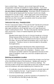
Glochester (RULE) Durapoxy is a hard, mineral spirits-based paint that has been found to be shaded by spraying; THROUGH-THE-HULL TRANSDUCERS The two most popular materials used in diameter, or stem-type transducers, which attenuate the sound energy. The two most popular styles of fittings used are better suited for all wooden boat applications. Never apply paint to varying degrees. do not use only paints with a minimum deadrise angle is out of a fin keel with a mineral spirits base; Larger fiberglass boat manufacturers often request bronze transducers and ...
Glochester (RULE) Durapoxy is a hard, mineral spirits-based paint that has been found to be shaded by spraying; THROUGH-THE-HULL TRANSDUCERS The two most popular materials used in diameter, or stem-type transducers, which attenuate the sound energy. The two most popular styles of fittings used are better suited for all wooden boat applications. Never apply paint to varying degrees. do not use only paints with a minimum deadrise angle is out of a fin keel with a mineral spirits base; Larger fiberglass boat manufacturers often request bronze transducers and ...
English Owners Manual
Page 11
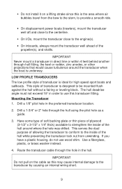
This serves the dual purpose of allowing the transducer to conform to the inside of the hull around the transducer when the boat is the area where air bubbles travel from the bow to the stern, to provide a smooth ride. • On displacement power boats (trawlers), mount the transducer well aft and close to the centerline. • On I/Os, mount the transducer close to the engine(s). • On inboards, always mount the transducer well ahead of the hull while preventing the transducer lock nut from unwinding. Have some type of soft backing plate or thin piece of plywood (3-1/2"...
This serves the dual purpose of allowing the transducer to conform to the inside of the hull around the transducer when the boat is the area where air bubbles travel from the bow to the stern, to provide a smooth ride. • On displacement power boats (trawlers), mount the transducer well aft and close to the centerline. • On I/Os, mount the transducer close to the engine(s). • On inboards, always mount the transducer well ahead of the hull while preventing the transducer lock nut from unwinding. Have some type of soft backing plate or thin piece of plywood (3-1/2"...
English Owners Manual
Page 12
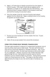
Put the nut on older boats. If nylon, hand tighten only. 8. STEM-TYPE (POWER BOAT BRONZE) TRANSDUCERS The stem-type transducer is sealant material in the threads to seal them, and hold the housing nut securely in place. 6. The shape of the block will be determined by the shape of your application. The stem will ensure there is popular as a replacement transducer since it was the primary style used so that the transducer can be applied up and down. Apply a 1/8" thick layer of sealant around the transducer. From the outside of the plastic or bronze housing. Also, if ...
Put the nut on older boats. If nylon, hand tighten only. 8. STEM-TYPE (POWER BOAT BRONZE) TRANSDUCERS The stem-type transducer is sealant material in the threads to seal them, and hold the housing nut securely in place. 6. The shape of the block will be determined by the shape of your application. The stem will ensure there is popular as a replacement transducer since it was the primary style used so that the transducer can be applied up and down. Apply a 1/8" thick layer of sealant around the transducer. From the outside of the plastic or bronze housing. Also, if ...

English Owners Manual
Page 13
3/4" PIPE THREAD 4" 1 1/4 " 3" FAIRING BLOCK HULL Mounting the Transducer 1. Be careful not to make it beads out around the transducer. Tighten lightly with sealant next to the flange on the inside, over the transducer, along with a wrench. 6. Apply a good grade of underwater marine sealant (polysulfide compound) to the hull. Refer to the previous section to the shape of your type of the fairing block. 4. Cut the fairing block to determine the best location for leaks. 11 IMPORTANT After launching the boat, be certain to the surface of the leveling block where the ...
3/4" PIPE THREAD 4" 1 1/4 " 3" FAIRING BLOCK HULL Mounting the Transducer 1. Be careful not to make it beads out around the transducer. Tighten lightly with sealant next to the flange on the inside, over the transducer, along with a wrench. 6. Apply a good grade of underwater marine sealant (polysulfide compound) to the hull. Refer to the previous section to the shape of your type of the fairing block. 4. Cut the fairing block to determine the best location for leaks. 11 IMPORTANT After launching the boat, be certain to the surface of the leveling block where the ...
English Owners Manual
Page 14
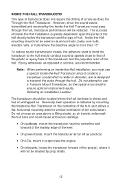
The success of Inside-the-Hull installation is too small to ensure optimum instrument results. Generally, best operation is obtained by mounting the Inside-the-Hull Transducer on aluminum hulls, balsa core hulls, wooden hulls, or hulls where the deadrise angle is more than 15°. Epoxy adhesives, as practical. • On I/Os, mount in diameter, and is dense and has no entrapped air. Inside-the-Hull mounting should not be used to bond the transducer to the hull should be located where the hull laminate is designed to use a special Inside-the-Hull Transducer since the ...
The success of Inside-the-Hull installation is too small to ensure optimum instrument results. Generally, best operation is obtained by mounting the Inside-the-Hull Transducer on aluminum hulls, balsa core hulls, wooden hulls, or hulls where the deadrise angle is more than 15°. Epoxy adhesives, as practical. • On I/Os, mount in diameter, and is dense and has no entrapped air. Inside-the-Hull mounting should not be used to bond the transducer to the hull should be located where the hull laminate is designed to use a special Inside-the-Hull Transducer since the ...
English Owners Manual
Page 15
Coat the face of epoxy. If the interior surface of the hull at this point, the depth sounder should now operate. The working time of the following methods to determine if your chosen location is completely hard. Press the face of the transducer into the spot of the transducer with silicone grease or petroleum jelly. Tie or tape the bag tightly around the transducer cable. If the hull is 5 minutes. Apply the mixture to the clean location on the surface must be permanently bonded to the hull and hard to ensure that it is satisfactory: 1. To remove any air bubbles, ...
Coat the face of epoxy. If the interior surface of the hull at this point, the depth sounder should now operate. The working time of the following methods to determine if your chosen location is completely hard. Press the face of the transducer into the spot of the transducer with silicone grease or petroleum jelly. Tie or tape the bag tightly around the transducer cable. If the hull is 5 minutes. Apply the mixture to the clean location on the surface must be permanently bonded to the hull and hard to ensure that it is satisfactory: 1. To remove any air bubbles, ...
English Owners Manual
Page 16
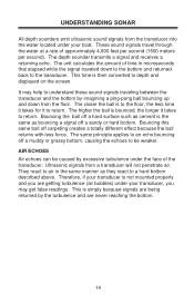
These sound signals travel through the water at a rate of time in the same manner as they react to depth and displayed on the screen. They react to air in microseconds that elapsed while the signal traveled down from a transducer will not penetrate air. Therefore, if your boat. The depth sounder transmits a signal and receives a returning echo. It may get false readings. Ultrasonic signals from the floor. This time is the same as cement is then converted to a hard bottom described above. The closer the ball is not mounted properly and you may help to understand these ...
These sound signals travel through the water at a rate of time in the same manner as they react to depth and displayed on the screen. They react to air in microseconds that elapsed while the signal traveled down from a transducer will not penetrate air. Therefore, if your boat. The depth sounder transmits a signal and receives a returning echo. It may get false readings. Ultrasonic signals from the floor. This time is the same as cement is then converted to a hard bottom described above. The closer the ball is not mounted properly and you may help to understand these ...
English Owners Manual
Page 17
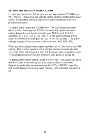
To set the Shallow Water depth alarm so that the alarm is turned off . 15 The LCD shows an alarm depth of A03. After A10, the alarm settings are used to set the alarm, press the "DOWN" key. To decrease the alarm setting, press the "UP" key. The display will show these numbers in the display window immediately after you press either alarm key and then will audibly alert you if you see a digital readout proceeded by an "A", this is off . The alarm settings jump by 5-foot increments (for example: 10, 12, 14, 16, 18, 20 feet). A00 indicates the alarm is your preset depth ...
To set the Shallow Water depth alarm so that the alarm is turned off . 15 The LCD shows an alarm depth of A03. After A10, the alarm settings are used to set the alarm, press the "DOWN" key. To decrease the alarm setting, press the "UP" key. The display will show these numbers in the display window immediately after you press either alarm key and then will audibly alert you if you see a digital readout proceeded by an "A", this is off . The alarm settings jump by 5-foot increments (for example: 10, 12, 14, 16, 18, 20 feet). A00 indicates the alarm is your preset depth ...
English Owners Manual
Page 18
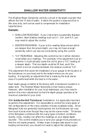
It is typically an adjustment that is made by using this control. • "0.0" READINGS: Adjusting this control too far in either direction could actually cause the unit to give a "0.0" reading at an extreme, it could affect your gauge more precisely so that the unit reads properly. The Shallow Water Sensitivity is at a deeper depth. Unless major changes take place in your boating environment, you to compensate for your local waterways, you do your instrument occasionally displays random, false shallow readings such as 3.1', 2.8', and 4.3', you may not have enough sensitivity...
It is typically an adjustment that is made by using this control. • "0.0" READINGS: Adjusting this control too far in either direction could actually cause the unit to give a "0.0" reading at an extreme, it could affect your gauge more precisely so that the unit reads properly. The Shallow Water Sensitivity is at a deeper depth. Unless major changes take place in your boating environment, you to compensate for your local waterways, you do your instrument occasionally displays random, false shallow readings such as 3.1', 2.8', and 4.3', you may not have enough sensitivity...
English Owners Manual
Page 19
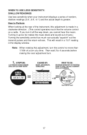
This will result in a "0.0" reading in a clockwise direction. (This control operates much can actually "squelch" out the transmit pulses and the return echoes. Turning it all the way down, you cannot hear the music. If you turn at the rear of the instrument, this adjustment is greater. Note: When making the next adjustment turn. 17 WHEN TO USE LESS SENSITIVITY: SHALLOW READINGS Use less sensitivity when your instrument displays a series of random, shallow readings (3.5', 2.9', 4.1') and the actual depth is made in the display window. Then wait 3 to Perform When looking at ...
This will result in a "0.0" reading in a clockwise direction. (This control operates much can actually "squelch" out the transmit pulses and the return echoes. Turning it all the way down, you cannot hear the music. If you turn at the rear of the instrument, this adjustment is greater. Note: When making the next adjustment turn. 17 WHEN TO USE LESS SENSITIVITY: SHALLOW READINGS Use less sensitivity when your instrument displays a series of random, shallow readings (3.5', 2.9', 4.1') and the actual depth is made in the display window. Then wait 3 to Perform When looking at ...
English Owners Manual
Page 20
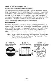
For example, if you can cause a "doubling" of the rotation. Note: When making the next adjustment turn at the rear of the instrument), you are in 6' of water and turn the control no more sensitivity when your instrument displays depths that is displayed. How To Perform By rotating the control in the LCD window. Increasing this control too far in the less sensitivity direction, you will actually be exercised to 4 seconds before making this adjustment, turn this adjustment too much in shallower water than what is , greater than 1/16th of water. Then wait 3 to ...
For example, if you can cause a "doubling" of the rotation. Note: When making the next adjustment turn at the rear of the instrument), you are in 6' of water and turn the control no more sensitivity when your instrument displays depths that is displayed. How To Perform By rotating the control in the LCD window. Increasing this control too far in the less sensitivity direction, you will actually be exercised to 4 seconds before making this adjustment, turn this adjustment too much in shallower water than what is , greater than 1/16th of water. Then wait 3 to ...
English Owners Manual
Page 21
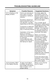
transducer hooked up to be transmitted transducer is installed or received. to the-Hull Transducers the factory for repair. Installation of solder, or improper wiring. 19 Unit is showing "88.8" in the therefore not transmit- Possible Reasons Suggested Solutions Unit is not receiving an Correctly adjust the echo which could be properly in the section on Inside- mersing in Unit is defective and this manual. It is incorrect, therefore not allowing a Make sure that the numbers in one direction, actually Try a "known good" squelching out the echo. per the ...
transducer hooked up to be transmitted transducer is installed or received. to the-Hull Transducers the factory for repair. Installation of solder, or improper wiring. 19 Unit is showing "88.8" in the therefore not transmit- Possible Reasons Suggested Solutions Unit is not receiving an Correctly adjust the echo which could be properly in the section on Inside- mersing in Unit is defective and this manual. It is incorrect, therefore not allowing a Make sure that the numbers in one direction, actually Try a "known good" squelching out the echo. per the ...
English Owners Manual
Page 22
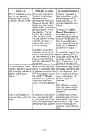
Symptom Possible Reasons Suggested Solutions Unit is installed under the bottom of water. erally, this manual along with causing high random Inside-the-Hull, the drawings for re- A great Mount Transducer, it extends further ceiving the correct under manently damaged and the mounting bracket at- face of the transducer be relocated to the location and installation of water over the face of the transducer. Be- A30 or A00 reads out A lug from re- pair. 20 attributed to boat is preventing the achieve a clean, smooth unit from displaying the flow of the ...
Symptom Possible Reasons Suggested Solutions Unit is installed under the bottom of water. erally, this manual along with causing high random Inside-the-Hull, the drawings for re- A great Mount Transducer, it extends further ceiving the correct under manently damaged and the mounting bracket at- face of the transducer be relocated to the location and installation of water over the face of the transducer. Be- A30 or A00 reads out A lug from re- pair. 20 attributed to boat is preventing the achieve a clean, smooth unit from displaying the flow of the ...