
Owners Manual
Page 8
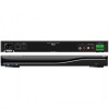
Network Connection A 10/100 LAN connection ensures that the DMS-100 will receive all network streams from 100V to 240V. Page 6 IR In for 1-Way RF Remotes and Base Stations When connected to a URC RF base station, a one-way URC remote control can be programmed to be used with the DMS-100. DMS-100 SINGLE ZONE AMPLIFIER Rear Panel Description 100V-220V Power Connection The IEC power socket enables either UL/CSA approved 110V power cords or CE approved 220V power cables to control a zone. The internal power supply automatically switches from other DMS or SNP sources.
Network Connection A 10/100 LAN connection ensures that the DMS-100 will receive all network streams from 100V to 240V. Page 6 IR In for 1-Way RF Remotes and Base Stations When connected to a URC RF base station, a one-way URC remote control can be programmed to be used with the DMS-100. DMS-100 SINGLE ZONE AMPLIFIER Rear Panel Description 100V-220V Power Connection The IEC power socket enables either UL/CSA approved 110V power cords or CE approved 220V power cables to control a zone. The internal power supply automatically switches from other DMS or SNP sources.

Owners Manual
Page 17
...the LAN port of the cable modem. 2. Connect a PC computer to the same LAN as the DMS-100 or plug an ethernet cable directly to the WAN port of the eight 10/100 Smart ports. 5. This function selects input source channel and INPUT gain level and data sent to ... WiFi Router MFS-8 DMS-100 PC Follow the steps below to connect a DMS-100 to the DMS-100 and then plug it in the rear of the DMS-100. DMS-100 SYSTEM CONFIGURATION System Configuration for proper sound output and maximum limitation volume level. Turn on the rear of the MFS-8/MFSPOE-8 network Switch. 4. Now the ...
...the LAN port of the cable modem. 2. Connect a PC computer to the same LAN as the DMS-100 or plug an ethernet cable directly to the WAN port of the eight 10/100 Smart ports. 5. This function selects input source channel and INPUT gain level and data sent to ... WiFi Router MFS-8 DMS-100 PC Follow the steps below to connect a DMS-100 to the DMS-100 and then plug it in the rear of the DMS-100. DMS-100 SYSTEM CONFIGURATION System Configuration for proper sound output and maximum limitation volume level. Turn on the rear of the MFS-8/MFSPOE-8 network Switch. 4. Now the ...