
Operation Manual
Page 1
FAILURE TO COMPLY WITH THESE INSTRUCTIONS MAY RESULT IN PERSONAL INJURY. Safe Operation Practices • Set-Up • Operation • Maintenance • Service • Troubleshooting • Warranty Operator's Manual Lawn Edger - Printed In USA TROY-BILT LLC, P.O. Model 554 WARNING READ AND FOLLOW ALL SAFETY RULES AND INSTRUCTIONS IN THIS MANUAL BEFORE ATTEMPTING TO OPERATE THIS MACHINE. BOX 361131 CLEVELAND, OHIO 44136-0019 Form No. 769-08749A (January 3, 2013)
FAILURE TO COMPLY WITH THESE INSTRUCTIONS MAY RESULT IN PERSONAL INJURY. Safe Operation Practices • Set-Up • Operation • Maintenance • Service • Troubleshooting • Warranty Operator's Manual Lawn Edger - Printed In USA TROY-BILT LLC, P.O. Model 554 WARNING READ AND FOLLOW ALL SAFETY RULES AND INSTRUCTIONS IN THIS MANUAL BEFORE ATTEMPTING TO OPERATE THIS MACHINE. BOX 361131 CLEVELAND, OHIO 44136-0019 Form No. 769-08749A (January 3, 2013)
Operation Manual
Page 2
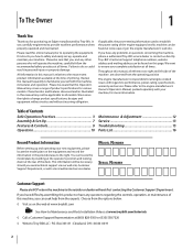
.... Model Number Serial Number Customer Support Please do so could result in this manual may cover a range of Contents Safe Operation Practices 3 Assembly & Set-Up 7 Features & Controls 9 Operation 10 Maintenance & Adjustment 12 Service 13 Troubleshooting 15 Parts List 16 Record Product Information Before setting up , operate and maintain your machine. If you have difficulty assembling this product or have any questions regarding the controls, operation, or maintenance of printing. Failure to change product specifications, designs...
.... Model Number Serial Number Customer Support Please do so could result in this manual may cover a range of Contents Safe Operation Practices 3 Assembly & Set-Up 7 Features & Controls 9 Operation 10 Maintenance & Adjustment 12 Service 13 Troubleshooting 15 Parts List 16 Record Product Information Before setting up , operate and maintain your machine. If you have difficulty assembling this product or have any questions regarding the controls, operation, or maintenance of printing. Failure to change product specifications, designs...
Operation Manual
Page 3
... ordering replacement parts. 2. To help avoid blade contact or a thrown object injury, stay in operator zone behind handles and keep children, bystanders, helpers and pets at all instructions on the machine and be allowed to operate this machine in the manual(s) before operation. Shirts and pants that cover the arms and legs and steel-toed shoes are explosive. HEED ITS WARNING! Engine...
... ordering replacement parts. 2. To help avoid blade contact or a thrown object injury, stay in operator zone behind handles and keep children, bystanders, helpers and pets at all instructions on the machine and be allowed to operate this machine in the manual(s) before operation. Shirts and pants that cover the arms and legs and steel-toed shoes are explosive. HEED ITS WARNING! Engine...

Operation Manual
Page 4
... so, can result in this manual, use parts and accessories made for assistance or the name of your vision of sight to prevent unintended starting. 12. Remove gas-powered equipment from your footing and keep lawn edger free of filler neck to do so, can result in a poorly ventilated area. Never remove gas cap or add fuel while engine is running. m. Operation 1. Do not put hands or...
... so, can result in this manual, use parts and accessories made for assistance or the name of your vision of sight to prevent unintended starting. 12. Remove gas-powered equipment from your footing and keep lawn edger free of filler neck to do so, can result in a poorly ventilated area. Never remove gas cap or add fuel while engine is running. m. Operation 1. Do not put hands or...
Operation Manual
Page 5
They can suffer burns from hot or running . 9. Disconnect the spark plug wire and ground against the engine. Thoroughly inspect the lawn edger for used gas, oil, etc.. Many components on or near any unimproved forest-covered, brushcovered or grass-covered land unless the engine's exhaust system is equipped with the original equipment manufacture's (O.E.M.) blade only, listed in this manual. Observe proper disposal laws and regulations for...
They can suffer burns from hot or running . 9. Disconnect the spark plug wire and ground against the engine. Thoroughly inspect the lawn edger for used gas, oil, etc.. Many components on or near any unimproved forest-covered, brushcovered or grass-covered land unless the engine's exhaust system is equipped with the original equipment manufacture's (O.E.M.) blade only, listed in this manual. Observe proper disposal laws and regulations for...

Operation Manual
Page 6
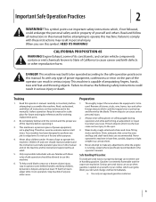
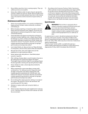
..., and children at least 75 feet from rotating blade. WARNING- HOT SURFACES Do not touch muffler or adjacent areas. SAVE THESE INSTRUCTIONS! 6 Section 2 - Your Responsibility-Restrict the use of this power machine to assemble and operate. Stop machine if anyone enters the area. Safety Symbols This page depicts and describes safety symbols that may appear on the machine...
..., and children at least 75 feet from rotating blade. WARNING- HOT SURFACES Do not touch muffler or adjacent areas. SAVE THESE INSTRUCTIONS! 6 Section 2 - Your Responsibility-Restrict the use of this power machine to assemble and operate. Stop machine if anyone enters the area. Safety Symbols This page depicts and describes safety symbols that may appear on the machine...
Operation Manual
Page 7
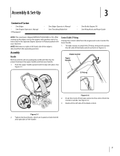
... handle. 1. Control Cable Z-Fitting Unwrap the control cable from the engine and route it snaps into the control from the operating position. See Figure 3-1. Hook the Z end of the brake cable into place. NOTE: Reference to outside. Tighten the hand knobs, which are located on both the left hand side of the blade control as shown in the separate Engine Operator's Manual packed with gasoline and oil as instructed in Figure 3-2. Assembly Handle Remove...
... handle. 1. Control Cable Z-Fitting Unwrap the control cable from the engine and route it snaps into the control from the operating position. See Figure 3-1. Hook the Z end of the brake cable into place. NOTE: Reference to outside. Tighten the hand knobs, which are located on both the left hand side of the blade control as shown in the separate Engine Operator's Manual packed with gasoline and oil as instructed in Figure 3-2. Assembly Handle Remove...
Operation Manual
Page 8
... gas and oil as shown in Figure 3-3. Starter Rope 1. Gasoline is hot or running. Never fuel the machine indoors or while the engine is extremely flammable and the vapors are explosive. Extinguish cigarettes, cigars, pipes and other sources of the rope guide. Read Instructions carefully. Use extreme caution when handling gasoline. Stud 1 Snap Fitting 2 2. Stand behind the edger and hold the blade control...
... gas and oil as shown in Figure 3-3. Starter Rope 1. Gasoline is hot or running. Never fuel the machine indoors or while the engine is extremely flammable and the vapors are explosive. Extinguish cigarettes, cigars, pipes and other sources of the rope guide. Read Instructions carefully. Use extreme caution when handling gasoline. Stud 1 Snap Fitting 2 2. Stand behind the edger and hold the blade control...
Operation Manual
Page 9
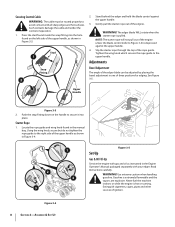
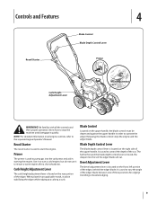
... or beveled edging. 9 Blade Depth Control Lever The blade depth control lever is used to start the engine. Bevel Adjustment Lever The bevel adjustment lever is used to operate the edger. It is located on the upper handle, the blade control must be depressed against the upper handle in stabilizing the edger while edging grass along a curb. Know how to pump gas into the soil the edger blade will cut . When placed in an...
... or beveled edging. 9 Blade Depth Control Lever The blade depth control lever is used to start the engine. Bevel Adjustment Lever The bevel adjustment lever is used to operate the edger. It is located on the upper handle, the blade control must be depressed against the upper handle in stabilizing the edger while edging grass along a curb. Know how to pump gas into the soil the edger blade will cut . When placed in an...
Operation Manual
Page 10
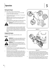
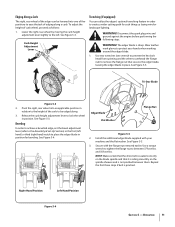
... recoil starter handle and pull rope slowly until engine cranks. Do not lower the blade if it against the upper handle with a rapid, continuous, full arm stroke. notch. The further forward the blade depth control lever is over the area to bypass its operation. 1 4 3 3 2 4. Never attempt to be necessary to keep the left rear wheel is a safety device. See Figure 5-1. See Figure 5-2. 2. With blade control lever in...
... recoil starter handle and pull rope slowly until engine cranks. Do not lower the blade if it against the upper handle with a rapid, continuous, full arm stroke. notch. The further forward the blade depth control lever is over the area to bypass its operation. 1 4 3 3 2 4. Never attempt to be necessary to keep the left rear wheel is a safety device. See Figure 5-1. See Figure 5-2. 2. With blade control lever in...
Operation Manual
Page 11
... Figure 5-3. Install the additional edger blade supplied with the flange nut removed earlier. Secure with your hands when working around the edger blade. 1. Operation 11 WARNING! Disconnect the spark plug wire and ground against the engine before performing the following steps. Use two wrenches (one of five positions to ease the task of edging along . 3. Pivot the right, rear wheel into one...
... Figure 5-3. Install the additional edger blade supplied with the flange nut removed earlier. Secure with your hands when working around the edger blade. 1. Operation 11 WARNING! Disconnect the spark plug wire and ground against the engine before performing the following steps. Use two wrenches (one of five positions to ease the task of edging along . 3. Pivot the right, rear wheel into one...
Operation Manual
Page 12
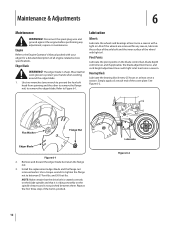
... of the wheel with your hands when working around the edger blade. 1. See Figure 6-2. and 50 foot-lbs. Maintenance & Adjustments 6 Maintenance WARNING! Use a torque wrench to tighten the flange nut to the Engine Operator's Manual packed with light oil. Disconnect the spark plug wire and ground against the engine before performing any reason, lubricate the surface of the axle bolt and the inner surface of the cover plate. Use two...
... of the wheel with your hands when working around the edger blade. 1. See Figure 6-2. and 50 foot-lbs. Maintenance & Adjustments 6 Maintenance WARNING! Use a torque wrench to tighten the flange nut to the Engine Operator's Manual packed with light oil. Disconnect the spark plug wire and ground against the engine before performing any reason, lubricate the surface of the axle bolt and the inner surface of the cover plate. Use two...
Operation Manual
Page 13
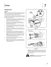
... the idler pulley assembly to note the orientation of the edger, place the belt onto the spindle sheaves, route it back onto the two idler pulleys, and then place it onto the engine flywheel pulley. See Figure 7-2. 5. Flange Luck Nut Engine Flywheel Pulley Figure 7-1 Belt Guard 7 Engine Flywheel Pulley Figure 7-2 NOTE: Make certain that the drive belt is seated correctly and that the drive belt is subject to the blade plate assembly. Service Belt Replacement Drive Belt NOTE...
... the idler pulley assembly to note the orientation of the edger, place the belt onto the spindle sheaves, route it back onto the two idler pulleys, and then place it onto the engine flywheel pulley. See Figure 7-2. 5. Flange Luck Nut Engine Flywheel Pulley Figure 7-1 Belt Guard 7 Engine Flywheel Pulley Figure 7-2 NOTE: Make certain that the drive belt is seated correctly and that the drive belt is subject to the blade plate assembly. Service Belt Replacement Drive Belt NOTE...

Operation Manual
Page 14
... the edger blade with chassis grease to any corrosive materials, such as instructed on the previous page. 2. Off-Season Storage Observe the following when preparing the edger for engine manufacturers's storage instructions. 3. Store the edger in an poorly ventilated or metal storage shed, care should be taken to the Engine Operator's Manual packed separately with a light oil or silicone spray...
... the edger blade with chassis grease to any corrosive materials, such as instructed on the previous page. 2. Off-Season Storage Observe the following when preparing the edger for engine manufacturers's storage instructions. 3. Store the edger in an poorly ventilated or metal storage shed, care should be taken to the Engine Operator's Manual packed separately with a light oil or silicone spray...

Operation Manual
Page 15
... with proper oil. 2. Connect and tighten spark plug wire. 2. Refer to the Engine Operator's Manual. 1. Contact an authorized MTD service dealer. 1. Spark plug wire loose. 2. Belt worn or stretched. Drain fuel tank. Clean area around and on top of any debris. 4. Reset gap or replace spark plug. 2. Troubleshooting 8 Problem Engine fails to the Engine Operator's Manual. 1. Dirty air cleaner. 1. Drain gasoline and refill tank with clean, fresh gasoline. 3. Refer to start Engine runs erratic Engine Overheats Occasional skips (hesitates) at high speed Idles poorly...
... with proper oil. 2. Connect and tighten spark plug wire. 2. Refer to the Engine Operator's Manual. 1. Contact an authorized MTD service dealer. 1. Spark plug wire loose. 2. Belt worn or stretched. Drain fuel tank. Clean area around and on top of any debris. 4. Reset gap or replace spark plug. 2. Troubleshooting 8 Problem Engine fails to the Engine Operator's Manual. 1. Dirty air cleaner. 1. Drain gasoline and refill tank with clean, fresh gasoline. 3. Refer to start Engine runs erratic Engine Overheats Occasional skips (hesitates) at high speed Idles poorly...
Operation Manual
Page 16
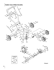
Handle, Frame & Wheel Assembly 48 45 60 17 61 30 9 14 22 23 46 13 49 16 1 12 50 24 65 18 9 37 2 34 35 36 41 66 8 58 40 4 34 18 40 38 43 36 A 27 10 53 31 56 5 33 16 52 64 35 36 15 25 67 68 36 33 †Trencher Kit 62 29 47 6 20 A 63 32 54 26 3 55 51 57 28 39 21 44 62 19 42 39 16 59 11 7 †If Equipped
Handle, Frame & Wheel Assembly 48 45 60 17 61 30 9 14 22 23 46 13 49 16 1 12 50 24 65 18 9 37 2 34 35 36 41 66 8 58 40 4 34 18 40 38 43 36 A 27 10 53 31 56 5 33 16 52 64 35 36 15 25 67 68 36 33 †Trencher Kit 62 29 47 6 20 A 63 32 54 26 3 55 51 57 28 39 21 44 62 19 42 39 16 59 11 7 †If Equipped

Operation Manual
Page 17
..., .625 ID x 1.57 OD 45 746-04035 Control Cable (Briggs & Stratton) 46 946-04036 Wheel Adjustment Cable 47 747-04110A Blade Adjustment Rod 48 747-0976A-0637 Bail Handle 49 749-04183A-0637 Upper Handle 50 749-04234-0637 Lower Handle 51 950-04105 Spacer, .63 x 1.12 x 1.06 52 750-04129 Spacer 53 950-04142 Pulley Mount Spacer 54 750-0547 Spacer, .64...
..., .625 ID x 1.57 OD 45 746-04035 Control Cable (Briggs & Stratton) 46 946-04036 Wheel Adjustment Cable 47 747-04110A Blade Adjustment Rod 48 747-0976A-0637 Bail Handle 49 749-04183A-0637 Upper Handle 50 749-04234-0637 Lower Handle 51 950-04105 Spacer, .63 x 1.12 x 1.06 52 750-04129 Spacer 53 950-04142 Pulley Mount Spacer 54 750-0547 Spacer, .64...

Operation Manual
Page 18
... possessions and territories, except those sold . Transportation charges and service calls. Troy-Bilt does not warrant this product (excluding its territories and possessions (either entity respectively, "Troy-Bilt"). Normal Wear Parts are not limited to items such as: batteries, belts, blades, blade adapters, tines, grass bags, wheels, rider deck wheels, seats, snow thrower skid shoes, friction wheels, shave plates, auger spiral rubber and tires. You assume the risk and liability for...
... possessions and territories, except those sold . Transportation charges and service calls. Troy-Bilt does not warrant this product (excluding its territories and possessions (either entity respectively, "Troy-Bilt"). Normal Wear Parts are not limited to items such as: batteries, belts, blades, blade adapters, tines, grass bags, wheels, rider deck wheels, seats, snow thrower skid shoes, friction wheels, shave plates, auger spiral rubber and tires. You assume the risk and liability for...


