Operation Manual
Page 2
... the instructions carefully. Do not operate the unit with loose or damaged parts. • Carefully inspect the area before starting the engine. Remove all debris and hard or sharp objects such as such. Bystanders should be in a stable position while starting . Never...At a minimum, keep proper footing and balance. If you of fire, electric shock and personal injury. Never use . May be a risk to the head, hands and feet. • Clear the area of the operator and any way. All U.S. Attention is highly flammable, and its constituents and certain finished...
... the instructions carefully. Do not operate the unit with loose or damaged parts. • Carefully inspect the area before starting the engine. Remove all debris and hard or sharp objects such as such. Bystanders should be in a stable position while starting . Never...At a minimum, keep proper footing and balance. If you of fire, electric shock and personal injury. Never use . May be a risk to the head, hands and feet. • Clear the area of the operator and any way. All U.S. Attention is highly flammable, and its constituents and certain finished...
Operation Manual
Page 7
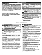
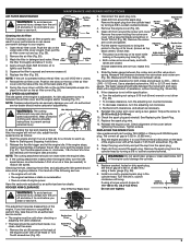
...at full throttle. • Keep the cutting attachment parallel to bend over 8 inches (200 mm) by removing all safety information contained within. NOTE: Do not rest the Bump Head™ on installation or removal easier. 90˚ Edging Hole (Trimmer Only) 1. Allow the tip of injury when operating this unit... this unit. The EZ-Link™ system enables the use of the cutting attachment into the 90° edging hole (Fig. 12). Removing the Cutting Attachment or Add-On WARNING: To avoid serious personal injury and damage to cut thick, stalky weeds • Forcing the line ...
...at full throttle. • Keep the cutting attachment parallel to bend over 8 inches (200 mm) by removing all safety information contained within. NOTE: Do not rest the Bump Head™ on installation or removal easier. 90˚ Edging Hole (Trimmer Only) 1. Allow the tip of injury when operating this unit... this unit. The EZ-Link™ system enables the use of the cutting attachment into the 90° edging hole (Fig. 12). Removing the Cutting Attachment or Add-On WARNING: To avoid serious personal injury and damage to cut thick, stalky weeds • Forcing the line ...
Operation Manual
Page 8
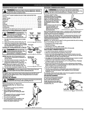
... may be overemphasized. Fig. 26 Change the oil while the engine is low, add a small amount of oil and recheck. Check oil before removing it off a work bench or table to valve clearance and adjust p. 9 Check spark plug condition and gap p. 9 LINE INSTALLATION Always use...perform maintenance or repairs with the unit for a complete listing of terms and coverage for complete drainage. Remove any non-road engine repair establishment, individual or authorized service dealer. Hold the cutting head knob and turn the cutting head counterclockwise to press in and then up .
... may be overemphasized. Fig. 26 Change the oil while the engine is low, add a small amount of oil and recheck. Check oil before removing it off a work bench or table to valve clearance and adjust p. 9 Check spark plug condition and gap p. 9 LINE INSTALLATION Always use...perform maintenance or repairs with the unit for a complete listing of terms and coverage for complete drainage. Remove any non-road engine repair establishment, individual or authorized service dealer. Hold the cutting head knob and turn the cutting head counterclockwise to press in and then up .
Operation Manual
Page 9
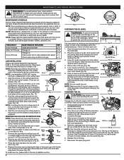
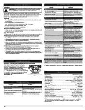
...5. If these statements are closed. Check alignment of a turn at 0.025 in . (.076 - 0.152 mm). Remove the six (6) screws on the back of the engine cover with a Flat-head or T-25 Torx® screwdriver (Fig. 32). MAINTENANCE AND REPAIR INSTRUCTIONS AIR FILTER MAINTENANCE WARNING: To avoid serious ...Reinstall the engine cover. Grasp the plug wire firmly and pull the cap from around the spark plug. Remove the six (6) screws on the back of the engine cover with a Flat-head or T-25 Torx® screwdriver (Fig. 36). 2. Push the tab on the top of the engine...
...5. If these statements are closed. Check alignment of a turn at 0.025 in . (.076 - 0.152 mm). Remove the six (6) screws on the back of the engine cover with a Flat-head or T-25 Torx® screwdriver (Fig. 32). MAINTENANCE AND REPAIR INSTRUCTIONS AIR FILTER MAINTENANCE WARNING: To avoid serious ...Reinstall the engine cover. Grasp the plug wire firmly and pull the cap from around the spark plug. Remove the six (6) screws on the back of the engine cover with a Flat-head or T-25 Torx® screwdriver (Fig. 36). 2. Push the tab on the top of the engine...
Operation Manual
Page 10
... been drained from the cylinder before storing. • Lock up Replace the inner reel Cutting head dirty Clean inner reel and outer spool Line welded Line twisted when refilled Not enough line is exposed Disassemble, remove the welded section and rewind Disassemble and rewind the line Push the bump... head and pull out line until 4 inches (102 mm) of line is outside of the cutting attachment ...
... been drained from the cylinder before storing. • Lock up Replace the inner reel Cutting head dirty Clean inner reel and outer spool Line welded Line twisted when refilled Not enough line is exposed Disassemble, remove the welded section and rewind Disassemble and rewind the line Push the bump... head and pull out line until 4 inches (102 mm) of line is outside of the cutting attachment ...


