Operation Manual
Page 15
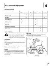
... Before each first 2 hours use Every 5 Hours Every 10 Hours Every 30 Hours See Engine Manual Check Motor Oil Level PP Clean Engine P P Check Drive Belt Tension P P Check Nuts and Bolts P P Lubricate Tiller P Check Gear Oil Level in Transmission P Check Tines for all moving parts to come to a complete stop, disconnect...
... Before each first 2 hours use Every 5 Hours Every 10 Hours Every 30 Hours See Engine Manual Check Motor Oil Level PP Clean Engine P P Check Drive Belt Tension P P Check Nuts and Bolts P P Lubricate Tiller P Check Gear Oil Level in Transmission P Check Tines for all moving parts to come to a complete stop, disconnect...
Operation Manual
Page 17
... needed . Badly worn tines will enter the soil first when the tiller moves forward. Secure the tine assembly to do so could damage the belt and/or belt cover. This will enter the soil first as a complete set. Remove the hex washer screw (1⁄4-20 x .500) and flat washer (....28 x .74 x .500) from the left " and "right" before attempting to reinstall the belt cover. Refer to Fig. 7-1 for tine identification and part numbers. When installing a single tine, be replaced either individually or as the tiller moves forward. Drain...
... needed . Badly worn tines will enter the soil first when the tiller moves forward. Secure the tine assembly to do so could damage the belt and/or belt cover. This will enter the soil first as a complete set. Remove the hex washer screw (1⁄4-20 x .500) and flat washer (....28 x .74 x .500) from the left " and "right" before attempting to reinstall the belt cover. Refer to Fig. 7-1 for tine identification and part numbers. When installing a single tine, be replaced either individually or as the tiller moves forward. Drain...
Operation Manual
Page 18
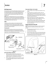
...;16-18 x .75) securing the transmission cover to drain through the top of the transmission. 7. Service 4. Tilt the left -side wheel. See Fig. 7-3 6. Reinstall the belt cover. 18 Section 7- Remove all dirt and clean the area around the transmission cover. See Fig. 7-3. Refill the engine with motor oil and replenish the...
...;16-18 x .75) securing the transmission cover to drain through the top of the transmission. 7. Service 4. Tilt the left -side wheel. See Fig. 7-3 6. Reinstall the belt cover. 18 Section 7- Remove all dirt and clean the area around the transmission cover. See Fig. 7-3. Refill the engine with motor oil and replenish the...
Operation Manual
Page 19
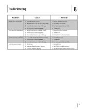
Tine holder mounting hardware missing. 2. Improper Depth Regulator setting. 3. Replace or adjust belts. 3. Tighten bolt. 1. Improper use of controls. 2. Worn tines. 2. Tighten bolt. 3. See Maintenance & Adjustments Section. 19... 3. Bolt loose in transmission pulley. 3. Remedy 1. Tighten bolt. 3. Internal transmission wear or damage. 1. Worn, broken, or mis-adjusted drive belt(s). 3. Forward Drive Belt slipping. Wheel Drive Pins not in transmission pulley. 3. Replace Tines. 2. Bolt loose in WHEEL DRIVE. 2. Review Operation section. 2. Troubleshooting 8 ...
Tine holder mounting hardware missing. 2. Improper Depth Regulator setting. 3. Replace or adjust belts. 3. Tighten bolt. 1. Improper use of controls. 2. Worn tines. 2. Tighten bolt. 3. See Maintenance & Adjustments Section. 19... 3. Bolt loose in transmission pulley. 3. Remedy 1. Tighten bolt. 3. Internal transmission wear or damage. 1. Worn, broken, or mis-adjusted drive belt(s). 3. Forward Drive Belt slipping. Wheel Drive Pins not in transmission pulley. 3. Replace Tines. 2. Bolt loose in WHEEL DRIVE. 2. Review Operation section. 2. Troubleshooting 8 ...
Operation Manual
Page 20
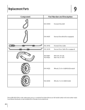
Replacement Parts Component 9 Part Number and Description 954-04090 Forward Drive Belt 954-04091 Reverse Drive Belt (If so equipped) 946-04413 946-04414 Forward Drive Cable Reverse Drive Cable (If so equipped) 742-04227 742-04226 Bolo Tine, 10" (LT) Bolo Tine, 10" (RT) 934-04232 Wheels, 13 x5 x 6 (65M & 655 model) 934-04453 Wheels, 11 x 4-4 (64M model) Phone (800) 828-5500 to order replacement parts or a complete Parts Manual (have your full model number and serial number ready). Parts Manual downloads are also available free of charge at www.troybilt.com. 20
Replacement Parts Component 9 Part Number and Description 954-04090 Forward Drive Belt 954-04091 Reverse Drive Belt (If so equipped) 946-04413 946-04414 Forward Drive Cable Reverse Drive Cable (If so equipped) 742-04227 742-04226 Bolo Tine, 10" (LT) Bolo Tine, 10" (RT) 934-04232 Wheels, 13 x5 x 6 (65M & 655 model) 934-04453 Wheels, 11 x 4-4 (64M model) Phone (800) 828-5500 to order replacement parts or a complete Parts Manual (have your full model number and serial number ready). Parts Manual downloads are also available free of charge at www.troybilt.com. 20
Operation Manual
Page 24
...and possessions (either entity respectively, "TroyBilt"). This limited warranty shall only apply if this product (excluding its Belts, Transmission and Attachments as identified. Troy-Bilt warrants the transmission (including all gears, shafts and housings) against defects in material and workmanship for a ...forth below ) against defects in material and workmanship for the life of the tiller, to obtain warranty coverage. Belts are not genuine Troy-Bilt parts. Log splitter pumps, valves, and cylinders have other than the original purchaser or to applicable manufacturer's ...
...and possessions (either entity respectively, "TroyBilt"). This limited warranty shall only apply if this product (excluding its Belts, Transmission and Attachments as identified. Troy-Bilt warrants the transmission (including all gears, shafts and housings) against defects in material and workmanship for a ...forth below ) against defects in material and workmanship for the life of the tiller, to obtain warranty coverage. Belts are not genuine Troy-Bilt parts. Log splitter pumps, valves, and cylinders have other than the original purchaser or to applicable manufacturer's ...
Service Manual
Page 3
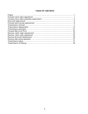
TABLE OF CONTENTS Engine: ...1 Forward clutch cable adjustment 1 Forward clutch cable assembly replacement 3 Drive belt replacement 5 Forward return spring replacement 6 Transmission removal: ...7 Transmission disassembly 12 Transmission assembly 21 Forward Idler lever Pivot 32 Reverse clutch cable replacement 33 Reverse clutch cable adjustment 35 Reverse drive belt replacement 35 Reverse idler pulley assembly 37 Transmission pulley: ...37 Transmission oil fill plug 38 0
TABLE OF CONTENTS Engine: ...1 Forward clutch cable adjustment 1 Forward clutch cable assembly replacement 3 Drive belt replacement 5 Forward return spring replacement 6 Transmission removal: ...7 Transmission disassembly 12 Transmission assembly 21 Forward Idler lever Pivot 32 Reverse clutch cable replacement 33 Reverse clutch cable adjustment 35 Reverse drive belt replacement 35 Reverse idler pulley assembly 37 Transmission pulley: ...37 Transmission oil fill plug 38 0

Service Manual
Page 8
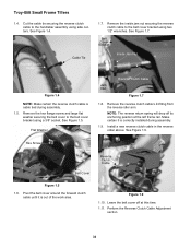
... will not fit through the belt cover. Remove the lower cable tie securing the forward clutch cable to the lower cable mounting bracket using a 3/8" socket. Forward Idler Lever Forward Clutch Cable Clutch Cable Z Fitting Hex Jam Nut Figure 3.5 3.6. Troy-Bilt Small Frame Tillers 3.5. Figure ...3.10 3.11. Remove the lower portion of the work area. Remove the hex flange screw and large flat washer securing the belt cover to the lower handlebar using a 3/8" wrench and a ...
... will not fit through the belt cover. Remove the lower cable tie securing the forward clutch cable to the lower cable mounting bracket using a 3/8" socket. Forward Idler Lever Forward Clutch Cable Clutch Cable Z Fitting Hex Jam Nut Figure 3.5 3.6. Troy-Bilt Small Frame Tillers 3.5. Figure ...3.10 3.11. Remove the lower portion of the work area. Remove the hex flange screw and large flat washer securing the belt cover to the lower handlebar using a 3/8" wrench and a ...
Service Manual
Page 9
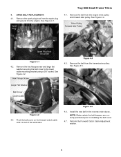
... screw and large flat washer securing the belt cover to installing the belt cover. 4.7. See Figure 4.2. See Figure 4.5. Install the new belt in the reverse order above. NOTE: Make certain the belt keepers are correctly positioned prior to the ...Belt Spark Plug Boot Grounded Figure 4.1 4.2. Figure 4.5 4.6. DRIVE BELT REPLACEMENT: 4.1. Pivot the belt cover on the forward clutch cable until it to the engine. Remove the belt from the engine drive pulley and forward idler pulley. Perform the Forward Clutch Cable Adjustment section. 5 See Figure 4.4. Spark Plug Troy-Bilt...
... screw and large flat washer securing the belt cover to installing the belt cover. 4.7. See Figure 4.2. See Figure 4.5. Install the new belt in the reverse order above. NOTE: Make certain the belt keepers are correctly positioned prior to the ...Belt Spark Plug Boot Grounded Figure 4.1 4.2. Figure 4.5 4.6. DRIVE BELT REPLACEMENT: 4.1. Pivot the belt cover on the forward clutch cable until it to the engine. Remove the belt from the engine drive pulley and forward idler pulley. Perform the Forward Clutch Cable Adjustment section. 5 See Figure 4.4. Spark Plug Troy-Bilt...
Service Manual
Page 10
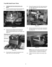
Troy-Bilt Small Frame Tillers 5. Remove the spark plug boot from the forward idler lever using needle nosed pliers. Spark Plug 5.4. Remove the hex flange screw and large flat washer securing the belt cover to the engine. Remove the lower hook of the return spring from the right engine bracket using a... Plug Boot Grounded Figure 5.1 5.2. Install a new return spring in the operators position) is out of the forward idler lever. Pivot the belt cover around the forward clutch cable until it to the lower cable mounting bracket using needle nose pliers. Hex Flange Screw Flat Washer...
Troy-Bilt Small Frame Tillers 5. Remove the spark plug boot from the forward idler lever using needle nosed pliers. Spark Plug 5.4. Remove the hex flange screw and large flat washer securing the belt cover to the engine. Remove the lower hook of the return spring from the right engine bracket using a... Plug Boot Grounded Figure 5.1 5.2. Install a new return spring in the operators position) is out of the forward idler lever. Pivot the belt cover around the forward clutch cable until it to the lower cable mounting bracket using needle nose pliers. Hex Flange Screw Flat Washer...
Service Manual
Page 11
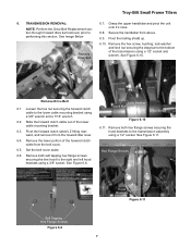
... cable out of the forward clutch cable from above. Set the belt cover aside. 6.6. See Figure 6.6. performing this section. Remove Drive Belt 6.10. Troy-Bilt Small Frame Tillers 6. TRANSMISSION REMOVAL: 6.7. Secure the handlebar from the belt cover. 6.5. Pivot the trailing shield up. Remove Drive Belt 6.1. Loosen the hex nut securing the forward clutch cable to the...
... cable out of the forward clutch cable from above. Set the belt cover aside. 6.6. See Figure 6.6. performing this section. Remove Drive Belt 6.10. Troy-Bilt Small Frame Tillers 6. TRANSMISSION REMOVAL: 6.7. Secure the handlebar from the belt cover. 6.5. Pivot the trailing shield up. Remove Drive Belt 6.1. Loosen the hex nut securing the forward clutch cable to the...
Service Manual
Page 13
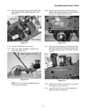
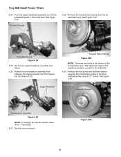
See Figure 6.17. Troy-Bilt Small Frame Tillers 6.20. Remove both self-tapping hex screws securing the lower forward cable mounting bracket to the left and right engine brackets to ... hex screws securing the left engine bracket using a 3/8" socket. See Figure 6.19. Lower the front of the unit and raise it up until the pulley/belt guard is setting on the ground. 9 Secure the upper handlebar in position from the right engine bracket using a 1/2" socket. See Figure 6.21. Remove the forward...
See Figure 6.17. Troy-Bilt Small Frame Tillers 6.20. Remove both self-tapping hex screws securing the lower forward cable mounting bracket to the left and right engine brackets to ... hex screws securing the left engine bracket using a 3/8" socket. See Figure 6.19. Lower the front of the unit and raise it up until the pulley/belt guard is setting on the ground. 9 Secure the upper handlebar in position from the right engine bracket using a 1/2" socket. See Figure 6.21. Remove the forward...
Service Manual
Page 14
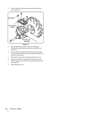
... Transmission Assembly Figure 6.26 NOTE: A small pry bar can be used for assistance, if necessary. 6.27. Remove the transmission assembly from the forward idler lever. Troy-Bilt Small Frame Tillers 6.24. Pivot the upper handlebar assembly up until the pulley/belt guard is used for the Tuffy tiller. 6.29. Forward Idle Lever Pulley...
... Transmission Assembly Figure 6.26 NOTE: A small pry bar can be used for assistance, if necessary. 6.27. Remove the transmission assembly from the forward idler lever. Troy-Bilt Small Frame Tillers 6.24. Pivot the upper handlebar assembly up until the pulley/belt guard is used for the Tuffy tiller. 6.29. Forward Idle Lever Pulley...
Service Manual
Page 38
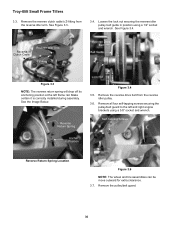
...arm. Remove the inside jam nut securing the reverse clutch cable to the belt cover bracket using side cutters. Belt Cover Bracket Inside Jam Nut Reverse Clutch Cable Jam Nut Figure 1.7 1.8. Leave the belt cover off its anchoring position at this time. 1.11. Flat Washer ...1.7. Install a new reverse clutch cable in the reverse order above. Reverse Clutch Cable Cable Tie Figure 1.4 NOTE: Make certain the reverse clutch cable is correctly installed during assembly. 1.5. Troy-Bilt Small Frame ...
...arm. Remove the inside jam nut securing the reverse clutch cable to the belt cover bracket using side cutters. Belt Cover Bracket Inside Jam Nut Reverse Clutch Cable Jam Nut Figure 1.7 1.8. Leave the belt cover off its anchoring position at this time. 1.11. Flat Washer ...1.7. Install a new reverse clutch cable in the reverse order above. Reverse Clutch Cable Cable Tie Figure 1.4 NOTE: Make certain the reverse clutch cable is correctly installed during assembly. 1.5. Troy-Bilt Small Frame ...

Service Manual
Page 39
Pull Out Troy-Bilt Small Frame Tillers 2.5. Adjust both hex jam nuts until it is engaged....it is between the end of removal, per the Reverse Clutch Cable Replacement section. 3. Flat Washer Hex Screw Belt Cover Figure 3.1 3.2. 2. See Figure 2.5. 1/8" to the belt cover bracket using a 3/8" socket. Check the adjustment on last time. 2.8. Fully engage the reverse clutch cable...fitting. Loosen the hex jam nuts securing the threaded portion of the work area. 35 Pivot the belt cover around the forward clutch cable until the exposed portion of the reverse clutch cable is out of...
Pull Out Troy-Bilt Small Frame Tillers 2.5. Adjust both hex jam nuts until it is engaged....it is between the end of removal, per the Reverse Clutch Cable Replacement section. 3. Flat Washer Hex Screw Belt Cover Figure 3.1 3.2. 2. See Figure 2.5. 1/8" to the belt cover bracket using a 3/8" socket. Check the adjustment on last time. 2.8. Fully engage the reverse clutch cable...fitting. Loosen the hex jam nuts securing the threaded portion of the work area. 35 Pivot the belt cover around the forward clutch cable until the exposed portion of the reverse clutch cable is out of...
Service Manual
Page 40
Make certain it is correctly installed during assembly. Remove the pulley/belt guard. 36 Reverse Clutch Cable Reverse Idler Arm Z-Fitting Reverse Drive Belt Belt Guide Figure 3.3 NOTE: The reverse return spring will drop off its anchoring position at the left and right ... in position using a 3/8" socket and wrench. Remove all four self-tapping screws securing the pulley/belt guard to the left frame rail. Troy-Bilt Small Frame Tillers 3.3. Remove the reverse drive belt from the reverse idler arm. See Figure 3.3. 3.4. See Figure 3.4. Reverse Return Spring Lock Nut Figure 3.4...
Make certain it is correctly installed during assembly. Remove the pulley/belt guard. 36 Reverse Clutch Cable Reverse Idler Arm Z-Fitting Reverse Drive Belt Belt Guide Figure 3.3 NOTE: The reverse return spring will drop off its anchoring position at the left and right ... in position using a 3/8" socket and wrench. Remove all four self-tapping screws securing the pulley/belt guard to the left frame rail. Troy-Bilt Small Frame Tillers 3.3. Remove the reverse drive belt from the reverse idler arm. See Figure 3.3. 3.4. See Figure 3.4. Reverse Return Spring Lock Nut Figure 3.4...
Service Manual
Page 41
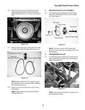
Troy-Bilt Small Frame Tillers 4. Transmission Pulley Inside-Out Reverse Drive Belt Forward Drive Belt Lock Nut Reverse Idler Pulley Flat Washers Figure 4.1 NOTE: The open center of the transmission pulley. TRANSMISSION PULLEY: 5.1....pulley. 37 The following picture shows the reverse idler assembly components in position before installing the transmission pulley. 3.10. Hex Screw Belleville Washer Belt Guide Open Center Hex Screw Transmission Pulley Figure 3.8 3.9. See Figure 5.1. REVERSE IDLER PULLEY ASSEMBLY: 4.1. See Figure 3.9. Flat Pulley Half ...
Troy-Bilt Small Frame Tillers 4. Transmission Pulley Inside-Out Reverse Drive Belt Forward Drive Belt Lock Nut Reverse Idler Pulley Flat Washers Figure 4.1 NOTE: The open center of the transmission pulley. TRANSMISSION PULLEY: 5.1....pulley. 37 The following picture shows the reverse idler assembly components in position before installing the transmission pulley. 3.10. Hex Screw Belleville Washer Belt Guide Open Center Hex Screw Transmission Pulley Figure 3.8 3.9. See Figure 5.1. REVERSE IDLER PULLEY ASSEMBLY: 4.1. See Figure 3.9. Flat Pulley Half ...


