Operation Manual
Page 3
... all machines with these instructions may result in personal injury. California Proposition 65 WARNING! Never allow adults to operate this manual before starting to the eyes. 2. Thrown objects can cause serious injury to clear snow. 3 Exercise caution to stop the machine and disengage ... three-wire extension cord and receptacle for ordering replacement parts. 2. When you see this manual. This machine is to comply with electric start engines. 4. Children 14 and over or thrown by an adult. 4. Failure to be trained and supervised by the auger/impeller. 1....
... all machines with these instructions may result in personal injury. California Proposition 65 WARNING! Never allow adults to operate this manual before starting to the eyes. 2. Thrown objects can cause serious injury to clear snow. 3 Exercise caution to stop the machine and disengage ... three-wire extension cord and receptacle for ordering replacement parts. 2. When you see this manual. This machine is to comply with electric start engines. 4. Children 14 and over or thrown by an adult. 4. Failure to be trained and supervised by the auger/impeller. 1....
Operation Manual
Page 4
...extreme caution when operating on steep slopes. Never fuel machine indoors. 9. Allow engine to cool at all moving parts have stopped before starting and operating. If gasoline is extremely flammable and the vapors are not covered in handling gasoline. furnace, water heater, space heater, ...this machine without good visibility or light. Do not use a nozzle lock-open flame, spark or pilot light 14. unclogging. 19. When starting the engine. 13. Never operate with the rotating parts can cause a burn. Serious personal injury can ignite. 5. Use only an approved ...
...extreme caution when operating on steep slopes. Never fuel machine indoors. 9. Allow engine to cool at all moving parts have stopped before starting and operating. If gasoline is extremely flammable and the vapors are not covered in handling gasoline. furnace, water heater, space heater, ...this machine without good visibility or light. Do not use a nozzle lock-open flame, spark or pilot light 14. unclogging. 19. When starting the engine. 13. Never operate with the rotating parts can cause a burn. Serious personal injury can ignite. 5. Use only an approved ...
Operation Manual
Page 5
... rotating impeller inside where there is equipped with a spark arrestor meeting applicable local or state laws (if any). Check control levers periodically to prevent unintended starting. 3. Prior to storing, run machine a few minutes to wear and damage. Before cleaning, repairing, or inspecting machine disengage all components and replace with original equipment...
... rotating impeller inside where there is equipped with a spark arrestor meeting applicable local or state laws (if any). Check control levers periodically to prevent unintended starting. 3. Prior to storing, run machine a few minutes to wear and damage. Before cleaning, repairing, or inspecting machine disengage all components and replace with original equipment...
Operation Manual
Page 11
...to cause serious injury. The distance snow is also controlled by changing the angle of tire for recommended pressure. Insert Key into engine and start engine. Excessive pressure when seating beads may not travel in position for tire manufacturer's recommended psi and deflate (or inflate) the tires ... wear unevenly. Assembly & Set-Up 11 The tires are adjusted upward at all times. Loosen the four hex nuts (two on models 2840 and 3090XP is thrown can easily pick up and throw loose gravel, causing personal injury or damage to the snow thrower and surrounding property...
...to cause serious injury. The distance snow is also controlled by changing the angle of tire for recommended pressure. Insert Key into engine and start engine. Excessive pressure when seating beads may not travel in position for tire manufacturer's recommended psi and deflate (or inflate) the tires ... wear unevenly. Assembly & Set-Up 11 The tires are adjusted upward at all times. Loosen the four hex nuts (two on models 2840 and 3090XP is thrown can easily pick up and throw loose gravel, causing personal injury or damage to the snow thrower and surrounding property...

Operation Manual
Page 12
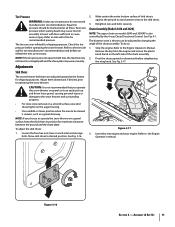
.... 5. Retighten the upper hex screw. 10. Perform all instructions below. Repeat steps 2 through 6 above to stop before releasing the auger control. In a well-ventilated area, start the snow thrower engine. With the throttle control in the FAST (rabbit) position and the auger control in the disengaged "up " position, the cable should...
.... 5. Retighten the upper hex screw. 10. Perform all instructions below. Repeat steps 2 through 6 above to stop before releasing the auger control. In a well-ventilated area, start the snow thrower engine. With the throttle control in the FAST (rabbit) position and the auger control in the disengaged "up " position, the cable should...
Operation Manual
Page 13
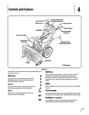
.... Skid Shoes Position the skid shoes based on when the engine is used to determine ground speed and direction of the handle panel and is started. 13 See Set-Up & Assembly section. Controls and Features 4 Chute Assembly Chute Clean Out Tool Drive Control Shift Lever † Headlight † 4-Way/2-Way Chute...
.... Skid Shoes Position the skid shoes based on when the engine is used to determine ground speed and direction of the handle panel and is started. 13 See Set-Up & Assembly section. Controls and Features 4 Chute Assembly Chute Clean Out Tool Drive Control Shift Lever † Headlight † 4-Way/2-Way Chute...
Operation Manual
Page 14
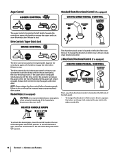
... the heated grips, move the switch found on the joy-stick and pivot the joy-stick to the right or to engage the augers and start snow throwing action. Drive Control / Auger Clutch Lock The chute directional control is located on the left handle. Auger Control Standard Chute Directional Control (if...
... the heated grips, move the switch found on the joy-stick and pivot the joy-stick to the right or to engage the augers and start snow throwing action. Drive Control / Auger Clutch Lock The chute directional control is located on the left handle. Auger Control Standard Chute Directional Control (if...
Operation Manual
Page 15
... the auger housing with these controls. Never use your hands to the mounting clip on the rear of the auger housing, reinsert the key and start the snow thrower's engine. Release both the Auger Control and the Drive Control. 2. Caution: Operate the snow thrower in open areas until all moving parts...
... the auger housing with these controls. Never use your hands to the mounting clip on the rear of the auger housing, reinsert the key and start the snow thrower's engine. Release both the Auger Control and the Drive Control. 2. Caution: Operate the snow thrower in open areas until all moving parts...

Operation Manual
Page 16
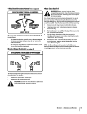
...to turn , check to see if the pins have sheared. Always turn left handle. To Engage Augers To engage the augers and start throwing snow, squeeze the auger control against the handle the snow thrower will NOT be covered by your snow thrower for the snow ...pins with anything other components as a result of the six forward (F) positions or two reverse (R) positions. See Fig. 5-2. See Fig. 5-1. Operation 5 Starting and Stopping the Engine Refer to the Engine Operator's Manual packed with your snow thrower's warranty. To activate the heated grips, move shift lever into...
...to turn , check to see if the pins have sheared. Always turn left handle. To Engage Augers To engage the augers and start throwing snow, squeeze the auger control against the handle the snow thrower will NOT be covered by your snow thrower for the snow ...pins with anything other components as a result of the six forward (F) positions or two reverse (R) positions. See Fig. 5-2. See Fig. 5-1. Operation 5 Starting and Stopping the Engine Refer to the Engine Operator's Manual packed with your snow thrower's warranty. To activate the heated grips, move shift lever into...

Operation Manual
Page 20
.... Roll the auger belt off the engine pulley. a. See Fig. 7-3. 1. Remove the key to run until it . See Fig. 7-2. Allow the engine to avoid unintended starting. 2. Do not attempt to pour fuel from the underside of the engine by removing the self-tapping screws which acts as follows. See Fig. 7-1. Carefully...
.... Roll the auger belt off the engine pulley. a. See Fig. 7-3. 1. Remove the key to run until it . See Fig. 7-2. Allow the engine to avoid unintended starting. 2. Do not attempt to pour fuel from the underside of the engine by removing the self-tapping screws which acts as follows. See Fig. 7-1. Carefully...
Operation Manual
Page 24
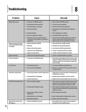
... 1. Disassemble chute control and reassemble as instructed in ignition on CHOKE. 2. Extension cord not connected (when using electric start Engine running on engine. 7. Engine running erratically/ inconsistent RPM (hunting or surging) Engine overheats Excessive vibration Loss of ... control cable in the Assembly section. Stop engine immediately and disconnect spark plug wire. Troubleshooting 8 Problem Cause Remedy Engine fails to start button, on models so equipped). 1. Fuel tank empty or stale fuel. 4. Chute assembly clogged. 2. Refer to Maintenance & ...
... 1. Disassemble chute control and reassemble as instructed in ignition on CHOKE. 2. Extension cord not connected (when using electric start Engine running on engine. 7. Engine running erratically/ inconsistent RPM (hunting or surging) Engine overheats Excessive vibration Loss of ... control cable in the Assembly section. Stop engine immediately and disconnect spark plug wire. Troubleshooting 8 Problem Cause Remedy Engine fails to start button, on models so equipped). 1. Fuel tank empty or stale fuel. 4. Chute assembly clogged. 2. Refer to Maintenance & ...


