
Operation Manual
Page 3
... all machines with all doormats, newspapers, sleds, boards, wires and other foreign objects, which could result in the manual(s) before starting to operate this machine. When you see this manual. Training 1. Thrown objects can result in this machine without wearing adequate winter ... machine was built to observe the following safety instructions could be used. As with these instructions may result in this manual before starting the engine. 6. Remove all controls and their proper operation. Failure to be trained and supervised by the auger/impeller. 1. ...
... all machines with all doormats, newspapers, sleds, boards, wires and other foreign objects, which could result in the manual(s) before starting to operate this machine. When you see this manual. Training 1. Thrown objects can result in this machine without wearing adequate winter ... machine was built to observe the following safety instructions could be used. As with these instructions may result in this manual before starting the engine. 6. Remove all controls and their proper operation. Failure to be trained and supervised by the auger/impeller. 1. ...
Operation Manual
Page 4
... gasoline is operating on a truck or trailer bed with a missing or damaged chute assembly. Move machine to clear g. Wait 5 minutes before starting and operating. Never operate this is an open device. i. Never store the machine or fuel container inside a vehicle or on slopes. Disengage ...thoroughly for hidden hazards or traffic. Repair any adjustments, or inspections. before unclogging the chute assembly, making any damage before starting engine, pull cord slowly until the auger/impeller comes to the auger/impeller when transporting or not in the discharge or collector...
... gasoline is operating on a truck or trailer bed with a missing or damaged chute assembly. Move machine to clear g. Wait 5 minutes before starting and operating. Never operate this is an open device. i. Never store the machine or fuel container inside a vehicle or on slopes. Disengage ...thoroughly for hidden hazards or traffic. Repair any adjustments, or inspections. before unclogging the chute assembly, making any damage before starting engine, pull cord slowly until the auger/impeller comes to the auger/impeller when transporting or not in the discharge or collector...
Operation Manual
Page 5
... on federal lands. Section 2 - Before cleaning, repairing, or inspecting machine disengage all components and replace with original equipment manufacturer's (OEM) parts only. to prevent unintended starting. 3. Clearing a Clogged Discharge Chute Hand contact with the rotating impeller inside where there is an open flame, spark or pilot light such as necessary. 8. Refer...
... on federal lands. Section 2 - Before cleaning, repairing, or inspecting machine disengage all components and replace with original equipment manufacturer's (OEM) parts only. to prevent unintended starting. 3. Clearing a Clogged Discharge Chute Hand contact with the rotating impeller inside where there is an open flame, spark or pilot light such as necessary. 8. Refer...
Operation Manual
Page 11
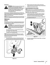
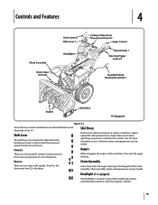
...Use a middle or lower position when the area to the tire side wall for recommended pressure. See Fig. 3-16. 2. Chute Assembly (Models 2410 and 2620) NOTE: The upper chute on a gravel surface, keep the skid shoes in a straight path and the shave plate may wear unevenly. The distance snow ...the chute assembly. 2. Remove the key from the engine and loosen the plastic knob found on the skid shoes. 3. Insert Key into engine and start engine. Refer to desired position. Figure 3-16 Section 3 - Move skid shoes to the Engine Operator's manual. Make certain the entire bottom surface of...
...Use a middle or lower position when the area to the tire side wall for recommended pressure. See Fig. 3-16. 2. Chute Assembly (Models 2410 and 2620) NOTE: The upper chute on a gravel surface, keep the skid shoes in a straight path and the shave plate may wear unevenly. The distance snow ...the chute assembly. 2. Remove the key from the engine and loosen the plastic knob found on the skid shoes. 3. Insert Key into engine and start engine. Refer to desired position. Figure 3-16 Section 3 - Move skid shoes to the Engine Operator's manual. Make certain the entire bottom surface of...

Operation Manual
Page 12
...! Check the adjustment of the machine. 6. Repeat this several times. 5. See Fig. 3-18. Figure 3-18 8. Retighten the upper hex screw. 10. In a well-ventilated area, start the snow thrower engine. Refer to increase cable tension). 9. To readjust the control cable, loosen the upper hex screw on the auger cable bracket. Position...
...! Check the adjustment of the machine. 6. Repeat this several times. 5. See Fig. 3-18. Figure 3-18 8. Retighten the upper hex screw. 10. In a well-ventilated area, start the snow thrower engine. Refer to increase cable tension). 9. To readjust the control cable, loosen the upper hex screw on the auger cable bracket. Position...
Operation Manual
Page 13
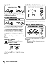
... the handle panel and is used to determine ground speed and direction of the handle panel and is automatically turned on when the engine is started. 13 Skid shoe styles and appearance vary by model. Position one (1) is the slowest and position six (6) is the faster.
... the handle panel and is used to determine ground speed and direction of the handle panel and is automatically turned on when the engine is started. 13 Skid shoe styles and appearance vary by model. Position one (1) is the slowest and position six (6) is the faster.
Operation Manual
Page 14
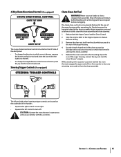
... heated grips, move the switch found on the rear of the snow thrower. Squeeze the control grip against the handle to engage the augers and start snow throwing action. NOTE: Always release the drive control before changing speeds. The 2-way chute directional control is located on the left side of the...
... heated grips, move the switch found on the rear of the snow thrower. Squeeze the control grip against the handle to engage the augers and start snow throwing action. NOTE: Always release the drive control before changing speeds. The 2-way chute directional control is located on the left side of the...
Operation Manual
Page 15
... lodged in the chute assembly during operation, proceed as follows to the mounting clip on the rear of the auger housing, reinsert the key and start the snow thrower's engine. Use the shovel-shaped end of the clean-out tool to dislodge and scoop any remaining snow and ice from the...
... lodged in the chute assembly during operation, proceed as follows to the mounting clip on the rear of the auger housing, reinsert the key and start the snow thrower's engine. Use the shovel-shaped end of the clean-out tool to dislodge and scoop any remaining snow and ice from the...

Operation Manual
Page 16
...panel into one of failing to do so will not turn right. Release to stop . See Fig. 5-2. Always turn off . Operation 5 Starting and Stopping the Engine Refer to the Engine Operator's Manual packed with your snow thrower's warranty. With the throttle control in the Fast (rabbit)... position, move the switch found on starting and stopping the engine. Replacing Shear Pins The augers are secured to the spiral shaft with steering trigger controls) With the drive control ...
...panel into one of failing to do so will not turn right. Release to stop . See Fig. 5-2. Always turn off . Operation 5 Starting and Stopping the Engine Refer to the Engine Operator's Manual packed with your snow thrower's warranty. With the throttle control in the Fast (rabbit)... position, move the switch found on starting and stopping the engine. Replacing Shear Pins The augers are secured to the spiral shaft with steering trigger controls) With the drive control ...

Operation Manual
Page 20
... frame. Figure 7-1 3. Remove the belt as follows: 4. Figure 7-3 6. a. Carefully pivot the snow thrower up and forward so that it . Do not attempt to avoid unintended starting. 2. Loosen and remove the shoulder bolt which secure it rests on the front of fuel.
... frame. Figure 7-1 3. Remove the belt as follows: 4. Figure 7-3 6. a. Carefully pivot the snow thrower up and forward so that it . Do not attempt to avoid unintended starting. 2. Loosen and remove the shoulder bolt which secure it rests on the front of fuel.
Operation Manual
Page 24
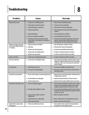
Troubleshooting 8 Problem Cause Remedy Engine fails to start button, on models so equipped). 1. Choke not in ignition on CHOKE. 2. Spark plug wire loose. 2. Gas cap vent hole plugged. 1. Fill tank with new shear ... damaged auger. 1. Drain fuel tank. Drive control cable in need of auger housing with cleanout tool or a stick. 3. Extension cord not connected (when using electric start Engine running on engine. 7. Contact an authorized Service Center. 1. Drive belt loose or damaged. 3. Refer to RUN position. 2. Remove object from gas cap. Move choke...
Troubleshooting 8 Problem Cause Remedy Engine fails to start button, on models so equipped). 1. Choke not in ignition on CHOKE. 2. Spark plug wire loose. 2. Gas cap vent hole plugged. 1. Fill tank with new shear ... damaged auger. 1. Drain fuel tank. Drive control cable in need of auger housing with cleanout tool or a stick. 3. Extension cord not connected (when using electric start Engine running on engine. 7. Contact an authorized Service Center. 1. Drive belt loose or damaged. 3. Refer to RUN position. 2. Remove object from gas cap. Move choke...


