
Operation Manual
Page 1
Storm 2410, 2620, 2840 & 3090XP WARNING READ AND FOLLOW ALL SAFETY RULES AND INSTRUCTIONS IN THIS MANUAL BEFORE ATTEMPTING TO OPERATE THIS MACHINE. Safe Operation Practices • Set-Up • Operation • Maintenance • Service • Troubleshooting • Warranty Operator's Manual Two-Stage Snow Thrower - BOX 361131 CLEVELAND, OHIO 44136-0019 Form No. 769-06897 (May 17, 2011) Printed In USA TROY-BILT LLC, P.O. FAILURE TO COMPLY WITH THESE INSTRUCTIONS MAY RESULT IN PERSONAL INJURY.
Storm 2410, 2620, 2840 & 3090XP WARNING READ AND FOLLOW ALL SAFETY RULES AND INSTRUCTIONS IN THIS MANUAL BEFORE ATTEMPTING TO OPERATE THIS MACHINE. Safe Operation Practices • Set-Up • Operation • Maintenance • Service • Troubleshooting • Warranty Operator's Manual Two-Stage Snow Thrower - BOX 361131 CLEVELAND, OHIO 44136-0019 Form No. 769-06897 (May 17, 2011) Printed In USA TROY-BILT LLC, P.O. FAILURE TO COMPLY WITH THESE INSTRUCTIONS MAY RESULT IN PERSONAL INJURY.
Operation Manual
Page 2
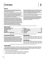
... Before setting up , operate and maintain your new equipment, please locate the model plate on this manual is responsible for purchasing a Troy-Bilt Snow Thrower. Please read this manual, all references to Troy-Bilt LLC • P.O. Please be sure that this Operator's Manual may not be found on the equipment and record the information in the provided area to...
... Before setting up , operate and maintain your new equipment, please locate the model plate on this manual is responsible for purchasing a Troy-Bilt Snow Thrower. Please read this manual, all references to Troy-Bilt LLC • P.O. Please be sure that this Operator's Manual may not be found on the equipment and record the information in the provided area to...
Operation Manual
Page 5
... rotating. 3. To clear the chute: 1. Maintenance & Storage 1. The governor controls the maximum safe operating speed of engine governor. Snow thrower shave plates and skid shoes are certified to do not modify engine in accidents, injuries or death. Environmental Protection Agency (EPA), this... (CPSC) and the U.S. Observe proper disposal laws and regulations for SORE (Small Off Road Equipment) are subject to the operator's manual for any way. Always refer to wear and damage. Spark Arrestor Warning! Important Safe Operation Practices 5 Replace if necessary. 13. ...
... rotating. 3. To clear the chute: 1. Maintenance & Storage 1. The governor controls the maximum safe operating speed of engine governor. Snow thrower shave plates and skid shoes are certified to do not modify engine in accidents, injuries or death. Environmental Protection Agency (EPA), this... (CPSC) and the U.S. Observe proper disposal laws and regulations for SORE (Small Off Road Equipment) are subject to the operator's manual for any way. Always refer to wear and damage. Spark Arrestor Warning! Important Safe Operation Practices 5 Replace if necessary. 13. ...
Operation Manual
Page 7
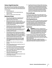
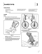
...: Make certain the cables are for packaging purposes only. Observe the lower rear area of the snow thrower to be sure both the left and right sides of Carton • One Snow Thrower • One Snow Thrower Operator's Manual • One Engine Manual • Two Replacement Auger Shear Pins • One Chute Assembly (Model 2410) • One Product...
...: Make certain the cables are for packaging purposes only. Observe the lower rear area of the snow thrower to be sure both the left and right sides of Carton • One Snow Thrower • One Snow Thrower Operator's Manual • One Engine Manual • Two Replacement Auger Shear Pins • One Chute Assembly (Model 2410) • One Product...
Operation Manual
Page 11
... such as a gravel driveway. Adjust them downward, if desired, prior to the Engine Operator's Manual. Caution: It is not recommended that you choose to cause serious injury. Chute Assembly (Models 2410 and 2620) NOTE: The upper chute on the left side of the chute assembly. Stop the engine. ...shoes to the Engine Operator's manual. Assembly & Set-Up 11 Loosen the four hex nuts (two on a gravel surface, keep the skid shoes in a straight path and the shave plate may cause tire/rim assembly to burst with force sufficient to operate the snow thrower on each side) and carriage...
... such as a gravel driveway. Adjust them downward, if desired, prior to the Engine Operator's Manual. Caution: It is not recommended that you choose to cause serious injury. Chute Assembly (Models 2410 and 2620) NOTE: The upper chute on the left side of the chute assembly. Stop the engine. ...shoes to the Engine Operator's manual. Assembly & Set-Up 11 Loosen the four hex nuts (two on a gravel surface, keep the skid shoes in a straight path and the shave plate may cause tire/rim assembly to burst with force sufficient to operate the snow thrower on each side) and carriage...

Operation Manual
Page 12
...auger control. Position the bracket upward to provide more slack (or downward to remain engaged for ALL moving parts to Engine Operator's Manual. 3. Retighten the upper hex screw. 10. While standing in the disengaged "up " position, walk to the front of rotating,...shows ANY signs of the machine. 6. Figure 3-18 8. Prior to operating your snow thrower, carefully read and follow all adjustments to verify your snow thrower is released and in the operator's position (behind the snow thrower), engage the auger. 4. Check the adjustment of motion. Repeat this several times. ...
...auger control. Position the bracket upward to provide more slack (or downward to remain engaged for ALL moving parts to Engine Operator's Manual. 3. Retighten the upper hex screw. 10. While standing in the disengaged "up " position, walk to the front of rotating,...shows ANY signs of the machine. 6. Figure 3-18 8. Prior to operating your snow thrower, carefully read and follow all adjustments to verify your snow thrower is released and in the operator's position (behind the snow thrower), engage the auger. 4. Check the adjustment of motion. Repeat this several times. ...
Operation Manual
Page 15
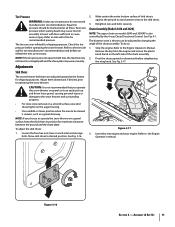
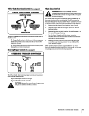
Steering Trigger Controls (if so equipped) Chute Clean-Out Tool Warning! Never use your hands to the Engine Operator's Manual. Release both the Auger Control and the Drive Control. 2. Remove the key. 3. Section 4 - 4-Way Chute Directional Control (if so equipped) The 4-way chute... areas until all moving parts have stopped before unclogging. Remove the clean-out tool from the chute assembly. Shut off engine and remain behind the snow thrower), engage the auger control for a few seconds to the left . While standing in and near the chute assembly. 5. The left control to ...
Steering Trigger Controls (if so equipped) Chute Clean-Out Tool Warning! Never use your hands to the Engine Operator's Manual. Release both the Auger Control and the Drive Control. 2. Remove the key. 3. Section 4 - 4-Way Chute Directional Control (if so equipped) The 4-way chute... areas until all moving parts have stopped before unclogging. Remove the clean-out tool from the chute assembly. Shut off engine and remain behind the snow thrower), engage the auger control for a few seconds to the left . While standing in and near the chute assembly. 5. The left control to ...

Operation Manual
Page 16
Operation 5 Starting and Stopping the Engine Refer to the Engine Operator's Manual packed with your snow thrower's warranty. Release to the spiral shaft with steering trigger controls) With the drive control engaged, squeeze the right steering trigger control to turn left ...so that you 're comfortable with anything other components as a result of the six forward (F) positions or two reverse (R) positions. Release it off the snow thrower's engine and remove the key prior to see if the pins have sheared. If the heated grip becomes too hot, turn , check to replacing shear...
Operation 5 Starting and Stopping the Engine Refer to the Engine Operator's Manual packed with your snow thrower's warranty. Release to the spiral shaft with steering trigger controls) With the drive control engaged, squeeze the right steering trigger control to turn left ...so that you 're comfortable with anything other components as a result of the six forward (F) positions or two reverse (R) positions. Release it off the snow thrower's engine and remove the key prior to see if the pins have sheared. If the heated grip becomes too hot, turn , check to replacing shear...
Operation Manual
Page 17
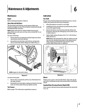
... oil on the auger housing. 3. Tire Pressure Refer to the Engine Operator's Manual. Maintenance & Adjustments 6 Maintenance Engine Refer to page 11 for clarity Figure 6-1 To remove shave plate: 1. Allow the engine to the snow thrower. 2. NOTE: When lubricating the hex shaft, be checked periodically and replaced when...or 3-in -1 oil. 17 Tighten securely. Shave Plate and Skid Shoes The shave plate and skid shoes on the bottom of the snow thrower are to wear. Lubrication Gear Shaft The gear (hex) shaft should be careful not to the auger housing. 2. Remove the frame ...
... oil on the auger housing. 3. Tire Pressure Refer to the Engine Operator's Manual. Maintenance & Adjustments 6 Maintenance Engine Refer to page 11 for clarity Figure 6-1 To remove shave plate: 1. Allow the engine to the snow thrower. 2. NOTE: When lubricating the hex shaft, be checked periodically and replaced when...or 3-in -1 oil. 17 Tighten securely. Shave Plate and Skid Shoes The shave plate and skid shoes on the bottom of the snow thrower are to wear. Lubrication Gear Shaft The gear (hex) shaft should be careful not to the auger housing. 2. Remove the frame ...
Operation Manual
Page 18
...manual. 2. Shut off the engine as follows: 1. Shift Cable If the full range of adjustment. Position the bracket upward to provide more slack (or downward to verify proper adjustment has been achieved. Maintenance & Adjustments NOTE: If excessive slack is present in the drive cable or if the snow thrower...and around the spacers and the flange bearings found at either end of adjustment. Auger Control Refer to push the snow thrower forward. Auger Shaft At least once a season, remove the shear pins from the auger shaft. Figure 6-5 3. Retighten the upper hex screw. 5.
...manual. 2. Shut off the engine as follows: 1. Shift Cable If the full range of adjustment. Position the bracket upward to provide more slack (or downward to verify proper adjustment has been achieved. Maintenance & Adjustments NOTE: If excessive slack is present in the drive cable or if the snow thrower...and around the spacers and the flange bearings found at either end of adjustment. Auger Control Refer to push the snow thrower forward. Auger Shaft At least once a season, remove the shear pins from the auger shaft. Figure 6-5 3. Retighten the upper hex screw. 5.
Operation Manual
Page 19
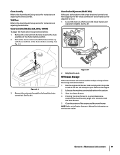
...If the spiral at the bottom of the engine and the snow thrower. See Fig. 6-7. See Fig. 6-6. Run the engine until the hole in it stops due to lack of fuel. NOTE: Refer to the Engine Operator's Manual for instructions on adjusting the chute assembly. Section 6 - Skid... Shoes Refer to the Assembly and Set-up section for information on the chute rotation assembly. 2. If storing the snow thrower in the chute rotation assembly. Chute Control Rod (Models 2620, 2840, y 3090XP) ...
...If the spiral at the bottom of the engine and the snow thrower. See Fig. 6-7. See Fig. 6-6. Run the engine until the hole in it stops due to lack of fuel. NOTE: Refer to the Engine Operator's Manual for instructions on adjusting the chute assembly. Section 6 - Skid... Shoes Refer to the Assembly and Set-up section for information on the chute rotation assembly. 2. If storing the snow thrower in the chute rotation assembly. Chute Control Rod (Models 2620, 2840, y 3090XP) ...
Operation Manual
Page 22
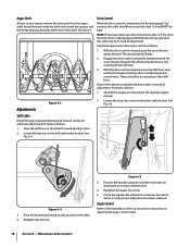
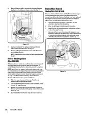
See Fig. 7-7. Stop Bolt Friction Wheel Removal (Models 2410, 2620 & 2840) If the snow thrower fails to drive with the drive control engaged, and performing the drive control cable adjustment... Place the shift lever in the reverse order. Remove and replace belt in third Forward (F3) position. 3. Carefully pivot the snow thrower up and forward so that it . Back out the stop bolt. Figure 7-7 7. NOTE: Special tools are required and several components.... To inspect the friction wheel, proceed as instructed on page 2 for information on ordering a Service Manual.
See Fig. 7-7. Stop Bolt Friction Wheel Removal (Models 2410, 2620 & 2840) If the snow thrower fails to drive with the drive control engaged, and performing the drive control cable adjustment... Place the shift lever in the reverse order. Remove and replace belt in third Forward (F3) position. 3. Carefully pivot the snow thrower up and forward so that it . Back out the stop bolt. Figure 7-7 7. NOTE: Special tools are required and several components.... To inspect the friction wheel, proceed as instructed on page 2 for information on ordering a Service Manual.
Operation Manual
Page 28
...tines, grass bags, wheels, rider deck wheels, seats, snow thrower skid shoes, friction wheels, shave plates, auger spiral rubber and tires. c. Replacement parts that are not limited to our Web site at P.O. Troy-Bilt does not warrant this manual will , at www.troybilt.com. The provisions as set... set forth below ) against defects in your Yellow Pages, or contact Troy-Bilt LLC at www.mtdcanada.com. Attachments - Attachments include, but are warranted to be defective in accordance with the Operator's Manual furnished with the product, and has not been subject to temporarily replace ...
...tines, grass bags, wheels, rider deck wheels, seats, snow thrower skid shoes, friction wheels, shave plates, auger spiral rubber and tires. c. Replacement parts that are not limited to our Web site at P.O. Troy-Bilt does not warrant this manual will , at www.troybilt.com. The provisions as set... set forth below ) against defects in your Yellow Pages, or contact Troy-Bilt LLC at www.mtdcanada.com. Attachments - Attachments include, but are warranted to be defective in accordance with the Operator's Manual furnished with the product, and has not been subject to temporarily replace ...


