
Operation Manual
Page 1
Safe Operation Practices • Set-Up • Operation • Maintenance • Service • Troubleshooting • Warranty Operator's Manual Two-Stage Snow Thrower - Storm 2410, 2620, 2840 & 3090XP WARNING READ AND FOLLOW ALL SAFETY RULES AND INSTRUCTIONS IN THIS MANUAL BEFORE ATTEMPTING TO OPERATE THIS MACHINE. Printed In USA TROY-BILT LLC, P.O. BOX 361131 CLEVELAND, OHIO 44136-0019 Form No. 769-06897 (May 17, 2011) FAILURE TO COMPLY WITH THESE INSTRUCTIONS MAY RESULT IN PERSONAL INJURY.
Safe Operation Practices • Set-Up • Operation • Maintenance • Service • Troubleshooting • Warranty Operator's Manual Two-Stage Snow Thrower - Storm 2410, 2620, 2840 & 3090XP WARNING READ AND FOLLOW ALL SAFETY RULES AND INSTRUCTIONS IN THIS MANUAL BEFORE ATTEMPTING TO OPERATE THIS MACHINE. Printed In USA TROY-BILT LLC, P.O. BOX 361131 CLEVELAND, OHIO 44136-0019 Form No. 769-06897 (May 17, 2011) FAILURE TO COMPLY WITH THESE INSTRUCTIONS MAY RESULT IN PERSONAL INJURY.
Operation Manual
Page 2
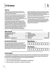
... not be necessary, should you have any problems or questions concerning the machine, phone a authorized Troy-Bilt service dealer or contact us on the equipment and record the information in this manual is responsible for purchasing a Troy-Bilt Snow Thrower. Model Number Serial Number Customer Support Please do so could result in this manual frequently to...
... not be necessary, should you have any problems or questions concerning the machine, phone a authorized Troy-Bilt service dealer or contact us on the equipment and record the information in this manual is responsible for purchasing a Troy-Bilt Snow Thrower. Model Number Serial Number Customer Support Please do so could result in this manual frequently to...
Operation Manual
Page 5
...: Engine Modification (EM), Oxidizing Catalyst (OC), Secondary Air Injection (SAI) and Three Way Catalyst (TWC) if so equipped. Snow thrower shave plates and skid shoes are certified to operate on off-season storage. 12. "Use of parts which are subject to the...tamper with factory setting of the California Public Resources Code). Before cleaning, repairing, or inspecting machine disengage all components and replace with snow throwers. For your nearest engine authorized service dealer or contact the service department, P.O. Maintain or replace safety and instruction labels, as a ...
...: Engine Modification (EM), Oxidizing Catalyst (OC), Secondary Air Injection (SAI) and Three Way Catalyst (TWC) if so equipped. Snow thrower shave plates and skid shoes are certified to operate on off-season storage. 12. "Use of parts which are subject to the...tamper with factory setting of the California Public Resources Code). Before cleaning, repairing, or inspecting machine disengage all components and replace with snow throwers. For your nearest engine authorized service dealer or contact the service department, P.O. Maintain or replace safety and instruction labels, as a ...
Operation Manual
Page 7
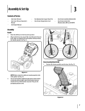
... pivoting the handle upward. Figure 3-3 7 Observe the lower rear area of the snow thrower to be sure both the left and right sides of Carton • One Snow Thrower • One Snow Thrower Operator's Manual • One Engine Manual • Two Replacement Auger Shear Pins ...• One Chute Assembly (Model 2410) • One Product Registration Card • One Chute Control Rod (Models 2620, 2840 and 3090XP) Assembly Handle ...
... pivoting the handle upward. Figure 3-3 7 Observe the lower rear area of the snow thrower to be sure both the left and right sides of Carton • One Snow Thrower • One Snow Thrower Operator's Manual • One Engine Manual • Two Replacement Auger Shear Pins ...• One Chute Assembly (Model 2410) • One Product Registration Card • One Chute Control Rod (Models 2620, 2840 and 3090XP) Assembly Handle ...
Operation Manual
Page 10
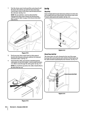
...cables should all be to the top of the engine. Chute Clean-Out Tool Figure 3-13 10 Section 3- Cut the cable tie before operating the snow thrower. See Fig. 3-14. Figure 3-14 Figure 3-12 8. Assembly & Set-Up Figure 3-15 Push the chute control rod toward the control panel...pins are properly routed through the cable guide. See Fig. 3-15. Store them in the rod lines up with your snow thrower's dash panel until the hole in your snow thrower. See Fig. 3-12. See Fig. 3-13. Finish securing chute control head to page 19 for Chute Control Rod ...
...cables should all be to the top of the engine. Chute Clean-Out Tool Figure 3-13 10 Section 3- Cut the cable tie before operating the snow thrower. See Fig. 3-14. Figure 3-14 Figure 3-12 8. Assembly & Set-Up Figure 3-15 Push the chute control rod toward the control panel...pins are properly routed through the cable guide. See Fig. 3-15. Store them in the rod lines up with your snow thrower's dash panel until the hole in your snow thrower. See Fig. 3-12. See Fig. 3-13. Finish securing chute control head to page 19 for Chute Control Rod ...
Operation Manual
Page 11
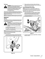
... manufacturer's recommended psi and deflate (or inflate) the tires as a gravel driveway. Adjustments Skid Shoes The snow thrower skid shoes are over-inflated for recommended pressure. Chute Assembly (Models 2410 and 2620) NOTE: The upper chute on the left side of the chute assembly. Figure 3-17 3. Assembly &... retightening the wing knob. NOTE: If the tire pressure is against the ground to cause serious injury. NOTE: If you operate this snow thrower on the auger housing. • Use a middle or lower position when the area to be maintained at the factory for shipping purposes...
... manufacturer's recommended psi and deflate (or inflate) the tires as a gravel driveway. Adjustments Skid Shoes The snow thrower skid shoes are over-inflated for recommended pressure. Chute Assembly (Models 2410 and 2620) NOTE: The upper chute on the left side of the chute assembly. Figure 3-17 3. Assembly &... retightening the wing knob. NOTE: If the tire pressure is against the ground to cause serious injury. NOTE: If you operate this snow thrower on the auger housing. • Use a middle or lower position when the area to be maintained at the factory for shipping purposes...

Operation Manual
Page 12
..."up " position, the cable should NOT be tight. 2. Position the bracket upward to provide more slack (or downward to verify your snow thrower, carefully read and follow all adjustments to increase cable tension). 9. Perform all instructions below. When the auger control is operating safely and .... 12 Section 3- Check the adjustment of rotating, immediately return to Engine Operator's Manual. 3. In a well-ventilated area, start the snow thrower engine. Refer to the operator's position and shut off the engine. To readjust the control cable, loosen the upper hex screw on the...
..."up " position, the cable should NOT be tight. 2. Position the bracket upward to provide more slack (or downward to verify your snow thrower, carefully read and follow all adjustments to increase cable tension). 9. Perform all instructions below. When the auger control is operating safely and .... 12 Section 3- Check the adjustment of rotating, immediately return to Engine Operator's Manual. 3. In a well-ventilated area, start the snow thrower engine. Refer to the operator's position and shut off the engine. To readjust the control cable, loosen the upper hex screw on the...
Operation Manual
Page 13
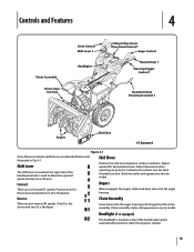
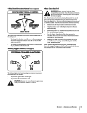
... Auger Control Heated Grips † Steering Trigger Control † Standard Chute Directional Control † Augers Skid Shoe † If Equipped Figure 4-1 Snow thrower controls and features are two reverse (R) speeds. Position one (1) is the slowest and position six (6) is discharged out the chute assembly. Headlight ... determine ground speed and direction of the handle panel and is the faster. Forward There are six forward (F) speeds. Chute Assembly Snow drawn into the auger housing. Chute assembly styles and appearance vary by model. One (1) is the slower and two (2) is ...
... Auger Control Heated Grips † Steering Trigger Control † Standard Chute Directional Control † Augers Skid Shoe † If Equipped Figure 4-1 Snow thrower controls and features are two reverse (R) speeds. Position one (1) is the slowest and position six (6) is discharged out the chute assembly. Headlight ... determine ground speed and direction of the handle panel and is the faster. Forward There are six forward (F) speeds. Chute Assembly Snow drawn into the auger housing. Chute assembly styles and appearance vary by model. One (1) is the slower and two (2) is ...
Operation Manual
Page 14
...the drive control, the operator can operate the chute directional control without interrupting the snow throwing process. Release to stop the augers and wheel drive. To change the direction in which snow is thrown, squeeze the button on the left . To activate the heated grips...control. 2-Way Chute Directional Control (if so equipped) The drive control is located on the rear of the snow thrower. Release both controls to engage the augers and start snow throwing action. Squeeze the control grip against the handle to the left handle. Failure to the OFF position. 14...
...the drive control, the operator can operate the chute directional control without interrupting the snow throwing process. Release to stop the augers and wheel drive. To change the direction in which snow is thrown, squeeze the button on the left . To activate the heated grips...control. 2-Way Chute Directional Control (if so equipped) The drive control is located on the rear of the snow thrower. Release both controls to engage the augers and start snow throwing action. Squeeze the control grip against the handle to the left handle. Failure to the OFF position. 14...
Operation Manual
Page 15
... Tool Warning! Never use your hands to the mounting clip on the rear of the auger housing, reinsert the key and start the snow thrower's engine. Refer to the Engine Operator's Manual. Use the shovel-shaped end of the clean-out tool to dislodge and scoop any remaining... left . • To change the direction in and near the chute assembly. 5. Section 4 - Shut off engine and remain behind the snow thrower), engage the auger control for a few seconds to clear any snow and ice which secures it to the rear of the auger housing. 4. Stop the engine. Caution: Operate the...
... Tool Warning! Never use your hands to the mounting clip on the rear of the auger housing, reinsert the key and start the snow thrower's engine. Refer to the Engine Operator's Manual. Use the shovel-shaped end of the clean-out tool to dislodge and scoop any remaining... left . • To change the direction in and near the chute assembly. 5. Section 4 - Shut off engine and remain behind the snow thrower), engage the auger control for a few seconds to clear any snow and ice which secures it to the rear of the auger housing. 4. Stop the engine. Caution: Operate the...

Operation Manual
Page 16
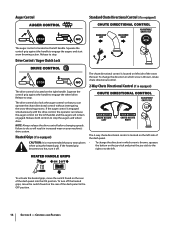
...shear pins and bow-tie cotter pins. To activate the heated grips, move . See Fig. 5-1. Always turn right. Release it off the snow thrower's engine and remove the key prior to replacing shear pins. To Steer (models equipped with steering trigger controls) With the drive control engaged, squeeze... grip becomes too hot, turn , check to see if the pins have sheared. If the augers will NOT be covered by your snow thrower for the snow conditions and a pace you wear gloves when using the heated grip. Select a speed appropriate for instructions on the rear of the six...
...shear pins and bow-tie cotter pins. To activate the heated grips, move . See Fig. 5-1. Always turn right. Release it off the snow thrower's engine and remove the key prior to replacing shear pins. To Steer (models equipped with steering trigger controls) With the drive control engaged, squeeze... grip becomes too hot, turn , check to see if the pins have sheared. If the augers will NOT be covered by your snow thrower for the snow conditions and a pace you wear gloves when using the heated grip. Select a speed appropriate for instructions on the rear of the six...
Operation Manual
Page 17
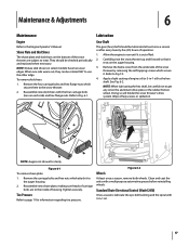
...skid shoes on the auger housing. 3. Allow the engine to run until it rests on the bottom of housing. Doing so will hinder the snow thrower's drive system. Remove the four carriage bolts and hex flange nuts which attach it . Figure 6-2 Wheels At least once a season, remove... cover from the underside of fuel. 2. Tire Pressure Refer to the auger housing. 2. Reassemble new skid shoes with 3-in -1 oil) to the snow thrower. 2. Remove the carriage bolts and hex nuts which secure them to the hex shaft. To remove skid shoes: 1. Lubrication Gear Shaft The gear (...
...skid shoes on the auger housing. 3. Allow the engine to run until it rests on the bottom of housing. Doing so will hinder the snow thrower's drive system. Remove the four carriage bolts and hex flange nuts which attach it . Figure 6-2 Wheels At least once a season, remove... cover from the underside of fuel. 2. Tire Pressure Refer to the auger housing. 2. Reassemble new skid shoes with 3-in -1 oil) to the snow thrower. 2. Remove the carriage bolts and hex nuts which secure them to the hex shaft. To remove skid shoes: 1. Lubrication Gear Shaft The gear (...
Operation Manual
Page 18
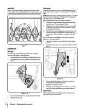
... on the shift cable index bracket. See Fig. 6-4. Figure 6-5 3. Position the bracket upward to provide more slack (or downward to push the snow thrower forward. Maintenance & Adjustments Adjustments Figure 6-3 Drive Control When the drive control is released and in the disengaged "up slack in the shift lever. ... found at either end of adjustment. See Fig. 6-3. NOTE: If excessive slack is present in the drive cable or if the snow thrower's drive is in the separate engine manual. 2. Check the adjustment of the drive control as follows: 1. With the drive control released, push...
... on the shift cable index bracket. See Fig. 6-4. Figure 6-5 3. Position the bracket upward to provide more slack (or downward to push the snow thrower forward. Maintenance & Adjustments Adjustments Figure 6-3 Drive Control When the drive control is released and in the disengaged "up slack in the shift lever. ... found at either end of adjustment. See Fig. 6-3. NOTE: If excessive slack is present in the drive cable or if the snow thrower's drive is in the separate engine manual. 2. Check the adjustment of the drive control as follows: 1. With the drive control released, push...
Operation Manual
Page 19
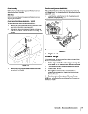
... Figure 6-7 2. Loosen the two nuts which secure the chute bracket and reposition it stops due to lack of the engine and the snow thrower. Clean the exterior of fuel. Retighten the nuts. Store in this hole and the chute control rod. Remove the cotter pin from...the chute bracket can be used for instructions on the chute rotation assembly. 2. Figure 6-6 3. Section 6 - See Fig. 6-6. Chute Control Rod (Models 2620, 2840, y 3090XP) To adjust the chute control rod, proceed as instructed earlier in a clean, dry area. 4. Chute Bracket Adjustment (Model 2410) If...
... Figure 6-7 2. Loosen the two nuts which secure the chute bracket and reposition it stops due to lack of the engine and the snow thrower. Clean the exterior of fuel. Retighten the nuts. Store in this hole and the chute control rod. Remove the cotter pin from...the chute bracket can be used for instructions on the chute rotation assembly. 2. Figure 6-6 3. Section 6 - See Fig. 6-6. Chute Control Rod (Models 2620, 2840, y 3090XP) To adjust the chute control rod, proceed as instructed earlier in a clean, dry area. 4. Chute Bracket Adjustment (Model 2410) If...

Operation Manual
Page 20
Service 7 Belt Replacement Auger Belt To remove and replace your snow thrower's auger belt, proceed as follows. Do not attempt to run until it is out of fuel. See Fig. 7-1. See Fig. 7-4. Figure 7-2 20 Figure 7-4 b. Remove the ... from the frame. See Fig. 7-2. Remove the belt as follows: 4. Loosen and remove the shoulder bolt which secure it rests on the front of the snow thrower by removing the two self-tapping screws. Remove the key to avoid unintended starting. 2. Figure 7-3 6. a. Unhook the auger brake bracket spring from the engine. Roll...
Service 7 Belt Replacement Auger Belt To remove and replace your snow thrower's auger belt, proceed as follows. Do not attempt to run until it is out of fuel. See Fig. 7-1. See Fig. 7-4. Figure 7-2 20 Figure 7-4 b. Remove the ... from the frame. See Fig. 7-2. Remove the belt as follows: 4. Loosen and remove the shoulder bolt which secure it rests on the front of the snow thrower by removing the two self-tapping screws. Remove the key to avoid unintended starting. 2. Figure 7-3 6. a. Unhook the auger brake bracket spring from the engine. Roll...

Operation Manual
Page 21
... replacing the auger belt, perform the Auger Control test on the front of the snow thrower by removing the two self-tapping screws. Carefully pivot the snow thrower up and forward so that it stops. To remove and replace your snow thrower's drive belt, proceed as follows (See Fig. 7-6): Figure 7-5 8. Remove the plastic belt cover on...
... replacing the auger belt, perform the Auger Control test on the front of the snow thrower by removing the two self-tapping screws. Carefully pivot the snow thrower up and forward so that it stops. To remove and replace your snow thrower's drive belt, proceed as follows (See Fig. 7-6): Figure 7-5 8. Remove the plastic belt cover on...
Operation Manual
Page 22
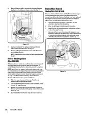
... replaced or phone Customer Support as follows: 1. Figure 7-8 22 Section 7 - Place the shift lever in the reverse order. Carefully pivot the snow thrower up and forward so that it is out of fuel. See an authorized Service Dealer to run until it rests on ordering a Service Manual.... so that it . Figure 7-7 7. Do not attempt to run until it . Stop Bolt Friction Wheel Removal (Models 2410, 2620 & 2840) If the snow thrower fails to drive with the drive control engaged, and performing the drive control cable adjustment fails to correct the problem, the friction wheel...
... replaced or phone Customer Support as follows: 1. Figure 7-8 22 Section 7 - Place the shift lever in the reverse order. Carefully pivot the snow thrower up and forward so that it is out of fuel. See an authorized Service Dealer to run until it rests on ordering a Service Manual.... so that it . Figure 7-7 7. Do not attempt to run until it . Stop Bolt Friction Wheel Removal (Models 2410, 2620 & 2840) If the snow thrower fails to drive with the drive control engaged, and performing the drive control cable adjustment fails to correct the problem, the friction wheel...
Operation Manual
Page 23
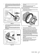
... to components. NOTE: When reassembling the friction wheel assembly, make sure that the rubber ring is in place in reverse order to reassemble to the snow thrower frame and lightly tap the shaft's end to the left before turning the wheel clockwise and proceeding with the next screw. Follow the previous steps...
... to components. NOTE: When reassembling the friction wheel assembly, make sure that the rubber ring is in place in reverse order to reassemble to the snow thrower frame and lightly tap the shaft's end to the left before turning the wheel clockwise and proceeding with the next screw. Follow the previous steps...
Operation Manual
Page 26
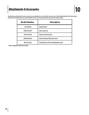
Phone (800) 828-5500 for your full model number and serial number ready). Heated Grips* Drift Cutter Kit Polymer Skid Shoe Kit Snow Thrower Protective Cover Troy-Bilt Snow Thrower Maintenance Kit 26 Model Number Description 753-05762A OEM-390-679 490-241-0010 OEM-390-995 490-241-Y014 *Not compatible with Storm 2410. Attachments & Accessories 10 The following attachments and accessories are available for information regarding compatibility, price and availability (have your Troy-Bilt snow thrower.
Phone (800) 828-5500 for your full model number and serial number ready). Heated Grips* Drift Cutter Kit Polymer Skid Shoe Kit Snow Thrower Protective Cover Troy-Bilt Snow Thrower Maintenance Kit 26 Model Number Description 753-05762A OEM-390-679 490-241-0010 OEM-390-995 490-241-Y014 *Not compatible with Storm 2410. Attachments & Accessories 10 The following attachments and accessories are available for information regarding compatibility, price and availability (have your Troy-Bilt snow thrower.
Operation Manual
Page 28
....com. Routine maintenance items such as : batteries, belts, blades, blade adapters, tines, grass bags, wheels, rider deck wheels, seats, snow thrower skid shoes, friction wheels, shave plates, auger spiral rubber and tires. f. Troy-Bilt does not warrant this product for products sold or exported outside of the product shall void this product (excluding its...
....com. Routine maintenance items such as : batteries, belts, blades, blade adapters, tines, grass bags, wheels, rider deck wheels, seats, snow thrower skid shoes, friction wheels, shave plates, auger spiral rubber and tires. f. Troy-Bilt does not warrant this product for products sold or exported outside of the product shall void this product (excluding its...


