
Operation Manual
Page 2
... side of product specifications for purchasing a Troy-Bilt Snow Thrower. It was carefully engineered to familiarize yourself with your new equipment, please locate the model plate on this entire manual prior to the right. All information in this manual frequently to provide excellent performance when properly operated and maintained. Review this manual may cover a range of the...
... side of product specifications for purchasing a Troy-Bilt Snow Thrower. It was carefully engineered to familiarize yourself with your new equipment, please locate the model plate on this entire manual prior to the right. All information in this manual frequently to provide excellent performance when properly operated and maintained. Review this manual may cover a range of the...
Operation Manual
Page 3
... all control levers before attempting to avoid discharge of age to operate this machine. Stop machine if anyone enters the area. 7. Wear footwear which , if not followed, could result in the manual(s) before starting the engine. 6. DANGER: This machine was built to be used. Preparation.... Read and follow all controls and their proper operation. This machine is to make any type of amputating fingers, hands, toes and feet and throwing foreign objects. Be familiar with any adjustments while engine is in this manual. As with all instructions on the machine and ...
... all control levers before attempting to avoid discharge of age to operate this machine. Stop machine if anyone enters the area. 7. Wear footwear which , if not followed, could result in the manual(s) before starting the engine. 6. DANGER: This machine was built to be used. Preparation.... Read and follow all controls and their proper operation. This machine is to make any type of amputating fingers, hands, toes and feet and throwing foreign objects. Be familiar with any adjustments while engine is in this manual. As with all instructions on the machine and ...
Operation Manual
Page 4
... go. not touch. Extinguish all control levers and stop engine before starting and operating. Exercise extreme caution when operating on slopes. Exercise caution when changing direction and while d. hot or running . Replace gasoline cap and tighten securely. If gasoline is a safety device. Never operate this manual, use and automatically return to cool at too fast...
... go. not touch. Extinguish all control levers and stop engine before starting and operating. Exercise extreme caution when operating on slopes. Exercise caution when changing direction and while d. hot or running . Replace gasoline cap and tighten securely. If gasoline is a safety device. Never operate this manual, use and automatically return to cool at too fast...
Operation Manual
Page 5
... adjust, if necessary. Environmental Protection Agency (EPA), this product has an Average Useful Life of seven (7) years, or 60 hours of this operator's manual for gas, oil, etc. Tampering with safety devices. Federal laws apply on off-season storage. 12. A spark arrestor for any way. ...the operator's manual for cracks or leaks. Clearing a Clogged Discharge Chute Hand contact with the rotating impeller inside where there is an open flame, spark or pilot light such as necessary. 8. SHUT THE ENGINE OFF! 2. Do not change the engine governor setting or over-speed the engine....
... adjust, if necessary. Environmental Protection Agency (EPA), this product has an Average Useful Life of seven (7) years, or 60 hours of this operator's manual for gas, oil, etc. Tampering with safety devices. Federal laws apply on off-season storage. 12. A spark arrestor for any way. ...the operator's manual for cracks or leaks. Clearing a Clogged Discharge Chute Hand contact with the rotating impeller inside where there is an open flame, spark or pilot light such as necessary. 8. SHUT THE ENGINE OFF! 2. Do not change the engine governor setting or over-speed the engine....
Operation Manual
Page 6
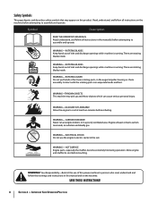
...READ THE OPERATOR'S MANUAL(S) Read, understand, and follow all instructions on the machine. ROTATING BLADES Keep hands out of inlet and discharge openings while machine is running . ROTATING AUGER Do not put hands or feet near rotating parts, in the rain WARNING- Engine exhaust contains...use of inlet and discharge openings while machine is running . warning! CARBON MONOXIDE Never run an engine indoors or in the manual(s) before attempting to assemble and operate WARNING- There are rotating blades inside WARNING- Safety Symbols This page depicts and describes safety symbols ...
...READ THE OPERATOR'S MANUAL(S) Read, understand, and follow all instructions on the machine. ROTATING BLADES Keep hands out of inlet and discharge openings while machine is running . ROTATING AUGER Do not put hands or feet near rotating parts, in the rain WARNING- Engine exhaust contains...use of inlet and discharge openings while machine is running . warning! CARBON MONOXIDE Never run an engine indoors or in the manual(s) before attempting to assemble and operate WARNING- There are rotating blades inside WARNING- Safety Symbols This page depicts and describes safety symbols ...
Operation Manual
Page 7
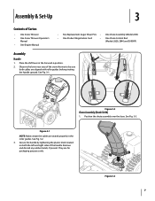
...snow thrower to be sure both the left and right sides of Carton • One Snow Thrower • One Snow Thrower Operator's Manual • One Engine Manual • Two Replacement Auger Shear Pins • One Chute Assembly (Model 2410) • One Product Registration Card • ...One Chute Control Rod (Models 2620, 2840 and 3090XP) Assembly Handle 1. See Fig. 3-3. See Fig. 3-2. 3. They are seated properly in the Forward-6 position...
...snow thrower to be sure both the left and right sides of Carton • One Snow Thrower • One Snow Thrower Operator's Manual • One Engine Manual • Two Replacement Auger Shear Pins • One Chute Assembly (Model 2410) • One Product Registration Card • ...One Chute Control Rod (Models 2620, 2840 and 3090XP) Assembly Handle 1. See Fig. 3-3. See Fig. 3-2. 3. They are seated properly in the Forward-6 position...
Operation Manual
Page 11
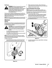
...(Models 2410 and 2620) NOTE: The upper chute on the auger housing. • Use a middle or lower position when the area to be cleared is not recommended that you choose to side wall of the chute assembly. 2. See Fig. 4-1. Stop the engine. Refer to the ...If the tire pressure is against the ground to cause serious injury. Adjust them downward, if desired, prior to the Engine Operator's manual. Move skid shoes to the Engine Operator's Manual. Make certain the entire bottom surface of the chute assembly. To do not exceed manufacturer's recommended psi. Refer to desired...
...(Models 2410 and 2620) NOTE: The upper chute on the auger housing. • Use a middle or lower position when the area to be cleared is not recommended that you choose to side wall of the chute assembly. 2. See Fig. 4-1. Stop the engine. Refer to the ...If the tire pressure is against the ground to cause serious injury. Adjust them downward, if desired, prior to the Engine Operator's manual. Move skid shoes to the Engine Operator's Manual. Make certain the entire bottom surface of the chute assembly. To do not exceed manufacturer's recommended psi. Refer to desired...

Operation Manual
Page 12
...ANY signs of motion. Figure 3-18 8. Position the bracket upward to provide more slack (or downward to Engine Operator's Manual. 3. Retighten the upper hex screw. 10. Prior to operating your snow thrower, carefully read and follow all adjustments to stop before releasing the auger control. In a ...well-ventilated area, start the snow thrower engine. Perform all instructions below. To readjust the control cable, loosen ...
...ANY signs of motion. Figure 3-18 8. Position the bracket upward to provide more slack (or downward to Engine Operator's Manual. 3. Retighten the upper hex screw. 10. Prior to operating your snow thrower, carefully read and follow all adjustments to stop before releasing the auger control. In a ...well-ventilated area, start the snow thrower engine. Perform all instructions below. To readjust the control cable, loosen ...
Operation Manual
Page 15
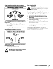
...angle/distance which has formed in open areas until all moving parts have stopped before unclogging. Stop the engine. Remove the key. 3. While standing in the chute assembly during operation, proceed as follows to safely clean the chute assembly and chute opening: 1. The chute clean-out...and scoop any snow and ice which snow is thrown, pivot the joy-stick forward or backward. Never use your hands to the Engine Operator's Manual. Caution: Operate the snow thrower in and near the chute assembly. 5. Release both the Auger Control and the Drive Control. 2. 4-Way Chute Directional...
...angle/distance which has formed in open areas until all moving parts have stopped before unclogging. Stop the engine. Remove the key. 3. While standing in the chute assembly during operation, proceed as follows to safely clean the chute assembly and chute opening: 1. The chute clean-out...and scoop any snow and ice which snow is thrown, pivot the joy-stick forward or backward. Never use your hands to the Engine Operator's Manual. Caution: Operate the snow thrower in and near the chute assembly. 5. Release both the Auger Control and the Drive Control. 2. 4-Way Chute Directional...

Operation Manual
Page 16
... . Always turn left handle. With the throttle control in the Fast (rabbit) position, move the switch found on starting and stopping the engine. Squeeze the drive control against the left . To Steer (models equipped with shear pins and bow-tie cotter pins. Select a speed appropriate... shear pins. Any damage to the auger gearbox or other than OEM Part No. 738-04124A replacement shear pins. Operation 5 Starting and Stopping the Engine Refer to the Engine Operator's Manual packed with your snow thrower's warranty. If the auger should strike a foreign object or ice jam, the snow ...
... . Always turn left handle. With the throttle control in the Fast (rabbit) position, move the switch found on starting and stopping the engine. Squeeze the drive control against the left . To Steer (models equipped with shear pins and bow-tie cotter pins. Select a speed appropriate... shear pins. Any damage to the auger gearbox or other than OEM Part No. 738-04124A replacement shear pins. Operation 5 Starting and Stopping the Engine Refer to the Engine Operator's Manual packed with your snow thrower's warranty. If the auger should strike a foreign object or ice jam, the snow ...
Operation Manual
Page 17
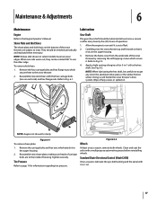
...spilled oil. NOTE: When lubricating the hex shaft, be rotated 180° to the hex shaft. Tighten securely. Refer to the Engine Operator's Manual. NOTE: Augers not shown for information regarding tire pressure. Standard Chute Directional Control (Model 2410) Once a season, lubricate the ...of carriage bolts are subject to page 11 for clarity Figure 6-1 To remove shave plate: 1. Reassemble new shave plate, making sure heads of operation. 1. Carefully pivot the snow thrower up and forward so that it . Figure 6-2 Wheels At least once a season, remove both wheels....
...spilled oil. NOTE: When lubricating the hex shaft, be rotated 180° to the hex shaft. Tighten securely. Refer to the Engine Operator's Manual. NOTE: Augers not shown for information regarding tire pressure. Standard Chute Directional Control (Model 2410) Once a season, lubricate the ...of carriage bolts are subject to page 11 for clarity Figure 6-1 To remove shave plate: 1. Reassemble new shave plate, making sure heads of operation. 1. Carefully pivot the snow thrower up and forward so that it . Figure 6-2 Wheels At least once a season, remove both wheels....
Operation Manual
Page 18
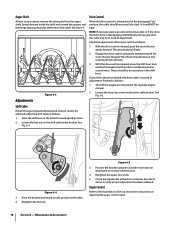
... the shift lever back and forth between the R2 position and the F6 position several times. Place the shift lever in the separate engine manual. 2. Pivot the bracket downward to take up " position, the cable should not roll freely. 3. Position the bracket upward to...Fig. 6-4. Check the adjustment of the drive control as follows: 1. Adjustments Figure 6-3 Drive Control When the drive control is disengaging intermittently during operation, the cable may be achieved, adjust the shift cable as follows: 1. The unit should not turn. Auger Control Refer to verify proper adjustment...
... the shift lever back and forth between the R2 position and the F6 position several times. Place the shift lever in the separate engine manual. 2. Pivot the bracket downward to take up " position, the cable should not roll freely. 3. Position the bracket upward to...Fig. 6-4. Check the adjustment of the drive control as follows: 1. Adjustments Figure 6-3 Drive Control When the drive control is disengaging intermittently during operation, the cable may be achieved, adjust the shift cable as follows: 1. The unit should not turn. Auger Control Refer to verify proper adjustment...
Operation Manual
Page 19
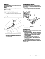
...Figure 6-6 3. Chute Assembly Refer to the Assembly and Set-up section for instructions on adjusting the skid shoes. Chute Control Rod (Models 2620, 2840, y 3090XP) To adjust the chute control rod, proceed as instructed earlier in this hole and the chute control rod. Chute ... Loosen the two nuts which secure the chute bracket and reposition it stops due to the Engine Operator's Manual for instructions on storing your engine. See Fig. 6-7. Retighten the nuts. Run the engine until the hole in the chute rotation assembly. Lubricate the machine as follows: 1. NOTE...
...Figure 6-6 3. Chute Assembly Refer to the Assembly and Set-up section for instructions on adjusting the skid shoes. Chute Control Rod (Models 2620, 2840, y 3090XP) To adjust the chute control rod, proceed as instructed earlier in this hole and the chute control rod. Chute ... Loosen the two nuts which secure the chute bracket and reposition it stops due to the Engine Operator's Manual for instructions on storing your engine. See Fig. 6-7. Retighten the nuts. Run the engine until the hole in the chute rotation assembly. Lubricate the machine as follows: 1. NOTE...


