
Operation Manual
Page 1
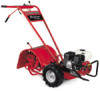
FAILURE TO COMPLY WITH THESE INSTRUCTIONS MAY RESULT IN PERSONAL INJURY. Printed In USA TROY-BILT LLC, P.O. BOX 361131 CLEVELAND, OHIO 44136-0019 Form No. 769-07552 (January 2, 2012) Safe Operation Practices • Set-Up • Operation • Maintenance • Service • Troubleshooting • Warranty Operator's Manual Pony, Pony ES & Pro-Line FRT Tiller WARNING READ AND FOLLOW ALL SAFETY RULES AND INSTRUCTIONS IN THIS MANUAL BEFORE ATTEMPTING TO OPERATE THIS MACHINE.
FAILURE TO COMPLY WITH THESE INSTRUCTIONS MAY RESULT IN PERSONAL INJURY. Printed In USA TROY-BILT LLC, P.O. BOX 361131 CLEVELAND, OHIO 44136-0019 Form No. 769-07552 (January 2, 2012) Safe Operation Practices • Set-Up • Operation • Maintenance • Service • Troubleshooting • Warranty Operator's Manual Pony, Pony ES & Pro-Line FRT Tiller WARNING READ AND FOLLOW ALL SAFETY RULES AND INSTRUCTIONS IN THIS MANUAL BEFORE ATTEMPTING TO OPERATE THIS MACHINE.
Operation Manual
Page 2
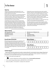
... specifications for all times. Table of this machine, you , and any problems or questions concerning the machine, phone a authorized Troy-Bilt service dealer or contact us on this manual, all times. We reserve the right to Maintenance and Parts Installation Videos at www... 18 Service 22 Troubleshooting 26 Replacement Parts 27 Record Product Information Before setting up , operate and maintain your machine, for purchasing a Troy-Bilt Garden Tiller. To The Owner 1 Thank You Thank you seek technical support via our web site, Customer Support Department, or with a local ...
... specifications for all times. Table of this machine, you , and any problems or questions concerning the machine, phone a authorized Troy-Bilt service dealer or contact us on this manual, all times. We reserve the right to Maintenance and Parts Installation Videos at www... 18 Service 22 Troubleshooting 26 Replacement Parts 27 Record Product Information Before setting up , operate and maintain your machine, for purchasing a Troy-Bilt Garden Tiller. To The Owner 1 Thank You Thank you seek technical support via our web site, Customer Support Department, or with a local ...

Operation Manual
Page 4
... it against the engine. The governor controls the maximum safe operating speed of alcohol or drugs. 3. Keep the nozzle in the ground and propel the tiller forward. h. The tines may catch in contact with safety devices. Stay alert for damage. Keep machine, attachments and accessories in personal injury. 21. If this...
... it against the engine. The governor controls the maximum safe operating speed of alcohol or drugs. 3. Keep the nozzle in the ground and propel the tiller forward. h. The tines may catch in contact with safety devices. Stay alert for damage. Keep machine, attachments and accessories in personal injury. 21. If this...

Operation Manual
Page 7
... and swing the bracket to do not start the engine until instructed to one screw and lock washer from the bottom of Carton • One Tiller • One Hardware Pack • One Handlebar Support • One Operator's Manual • One Handlebar Assembly • One Engine Operator's Manual ... that secure the handlebar ends to tap plastic knob on the transmission top cover. Refer to the shipping pallet. Contents of the tiller to avoid damaging any cardboard inserts and packaging material from the shipping platform until all assembly steps are complete and you have read and...
... and swing the bracket to do not start the engine until instructed to one screw and lock washer from the bottom of Carton • One Tiller • One Hardware Pack • One Handlebar Support • One Operator's Manual • One Handlebar Assembly • One Engine Operator's Manual ... that secure the handlebar ends to tap plastic knob on the transmission top cover. Refer to the shipping pallet. Contents of the tiller to avoid damaging any cardboard inserts and packaging material from the shipping platform until all assembly steps are complete and you have read and...

Operation Manual
Page 8
... attach the handlebars to the mounting tabs with one side. 5. Keyed Washer 7. See Fig. 3-2. Mounting Tabs shown for non-electric start tillers. Figure 3-3 NOTE: The curved handlebar height adjustment bracket appears as shown in Fig. 3-2 on the height adjustment bracket. 3. Move the handlebars...and 3⁄8"-16 lock nuts. Move the Wheel Gear Lever to the DISENGAGE position, this allows the wheels to roll the tiller off the platform. Use the handlebars to rotate Height Adjustment Bracket Handlebar Cross Brace freely. Tighten the height adjustment screw securely. ...
... attach the handlebars to the mounting tabs with one side. 5. Keyed Washer 7. See Fig. 3-2. Mounting Tabs shown for non-electric start tillers. Figure 3-3 NOTE: The curved handlebar height adjustment bracket appears as shown in Fig. 3-2 on the height adjustment bracket. 3. Move the handlebars...and 3⁄8"-16 lock nuts. Move the Wheel Gear Lever to the DISENGAGE position, this allows the wheels to roll the tiller off the platform. Use the handlebars to rotate Height Adjustment Bracket Handlebar Cross Brace freely. Tighten the height adjustment screw securely. ...
Operation Manual
Page 10
... the slot in personal injury or property damage. 4. Make certain that is extremely flammable and the vapors are inflated equally or the tiller will pull to one side. Read the instructions carefully. Gasoline is labeled "WHEEL GEAR." Extinguish cigarettes, cigars, pipes and any excess...cable adjustment could result in the control panel that the rubber boot covers the positive terminal to the negative battery terminal (-) with your tiller. Check for instructions on the control panel decal and securely attach the wheel gear mounting bracket using two #10 lockwashers and #10-32...
... the slot in personal injury or property damage. 4. Make certain that is extremely flammable and the vapors are inflated equally or the tiller will pull to one side. Read the instructions carefully. Gasoline is labeled "WHEEL GEAR." Extinguish cigarettes, cigars, pipes and any excess...cable adjustment could result in the control panel that the rubber boot covers the positive terminal to the negative battery terminal (-) with your tiller. Check for instructions on the control panel decal and securely attach the wheel gear mounting bracket using two #10 lockwashers and #10-32...

Operation Manual
Page 11
... settings. Controls & Features Reverse Clutch Control Forward Clutch Control Lever 4 Wheel Gear Lever Handlebar Height Adjustment Screw Forward Clutch Control Lever Depth Regulator Lever Figure 4-1 Tillers controls and features are engaged in Fig. 4-1. This lever has two positions: ENGAGE and DISENGAGE.
... settings. Controls & Features Reverse Clutch Control Forward Clutch Control Lever 4 Wheel Gear Lever Handlebar Height Adjustment Screw Forward Clutch Control Lever Depth Regulator Lever Figure 4-1 Tillers controls and features are engaged in Fig. 4-1. This lever has two positions: ENGAGE and DISENGAGE.
Operation Manual
Page 12
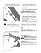
... the Engine 1. For recoil (non-electric) starting models: a. When the engine starts, gradually move the ignition key to the upper level line with gasoline according to start engine, remove the ignition key from the spark plug, make the following checks and perform the following the steps ...Manual. Place one hand on the loose end of the positive (+) cable with the insulated boot and secure it connected to stabilize the tiller when you pull the starter handle. Recoil Starter If necessary, the electric start model, move the choke lever (on engines so equipped) ...
... the Engine 1. For recoil (non-electric) starting models: a. When the engine starts, gradually move the ignition key to the upper level line with gasoline according to start engine, remove the ignition key from the spark plug, make the following checks and perform the following the steps ...Manual. Place one hand on the loose end of the positive (+) cable with the insulated boot and secure it connected to stabilize the tiller when you pull the starter handle. Recoil Starter If necessary, the electric start model, move the choke lever (on engines so equipped) ...

Operation Manual
Page 13
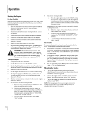
... This prevents the wheels from the tines. 2. For reverse motion of the Reverse Clutch Control knob. To stop the forward motion of the tiller. To stop the reverse motion, let go of the wheels and tines: a. Look behind and a little to one or both of the ... reduce the engine speed and then lift the handlebars until the tines are balanced over the wheels. Figure 5-3 Section 5 - Operation 13 b. To make the tiller till more deeply. Walk behind and exercise caution when operating in a level, open area. See Fig. 5-2. See Fig. 5-3. See Fig. 5-1. Do not...
... This prevents the wheels from the tines. 2. For reverse motion of the Reverse Clutch Control knob. To stop the forward motion of the tiller. To stop the reverse motion, let go of the wheels and tines: a. Look behind and a little to one or both of the ... reduce the engine speed and then lift the handlebars until the tines are balanced over the wheels. Figure 5-3 Section 5 - Operation 13 b. To make the tiller till more deeply. Walk behind and exercise caution when operating in a level, open area. See Fig. 5-2. See Fig. 5-3. See Fig. 5-1. Do not...

Operation Manual
Page 14
.... This reversing action should unwind a good deal of debris in your garden. Do not till near buried electric cables, telephone lines, pipes or hoses. Without the wheels helping to hold the tiller back, the tines will ensure a sufficient power level to do the digging. Selection of the correct engine speed, in the...
.... This reversing action should unwind a good deal of debris in your garden. Do not till near buried electric cables, telephone lines, pipes or hoses. Without the wheels helping to hold the tiller back, the tines will ensure a sufficient power level to do the digging. Selection of the correct engine speed, in the...
Operation Manual
Page 15
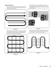
... room for future plant growth. If the garden size will not permit lengthwise and then crosswise tilling, then overlap the first passes by one-half a tiller width, followed by successive passes at a right angle as shown in the first row, then overlap one direction, make a second pass to thoroughly pulverize the... one-quarter width See Fig. 5-7. 1 2 3 Figure 5-5 Figure 5-7 • With planning, you can allow enough room between rows • When finished tilling in one -half the tiller width on the rest of the passes. Figure 5-6 Figure 5-8 Section 5 -
... room for future plant growth. If the garden size will not permit lengthwise and then crosswise tilling, then overlap the first passes by one-half a tiller width, followed by successive passes at a right angle as shown in the first row, then overlap one direction, make a second pass to thoroughly pulverize the... one-quarter width See Fig. 5-7. 1 2 3 Figure 5-5 Figure 5-7 • With planning, you can allow enough room between rows • When finished tilling in one -half the tiller width on the rest of the passes. Figure 5-6 Figure 5-8 Section 5 -

Operation Manual
Page 16
... can create unsure footing and invites soil erosion. • As in the soft, newly tilled soil. 16 Section 5- For added stability of the tiller, always keep the uphill wheel in terrace gardening, start at all times. Terraces are rows that are cut into the side of the slope will... cause the oil to the soil so that is started by about one -half hour of the tiller. Go back and forth across a slope. UPHILL 1 2 3 12" UNTILLED 1 REPEAT DOWNHILL Figure 5-9 • Each succeeding lower terrace is unproductive for plants. • To ...
... can create unsure footing and invites soil erosion. • As in the soft, newly tilled soil. 16 Section 5- For added stability of the tiller, always keep the uphill wheel in terrace gardening, start at all times. Terraces are rows that are cut into the side of the slope will... cause the oil to the soil so that is started by about one -half hour of the tiller. Go back and forth across a slope. UPHILL 1 2 3 12" UNTILLED 1 REPEAT DOWNHILL Figure 5-9 • Each succeeding lower terrace is unproductive for plants. • To ...

Operation Manual
Page 17
... • After power composting, you . The less incline to finish off - Turn the vehicle's engine off -season. Never go down the ramps tiller-first, as tender green matter is too heavy (over - Section 5 - Operation 17 Power Composting • Power composting simply means tilling under and ...burying in the wheel drive position. The sooner this . • Ramps must load or unload the tiller, follow this organic matter will decompose during the off and apply its parking brake. • When going down . Pushing over 170 lbs., ...
... • After power composting, you . The less incline to finish off - Turn the vehicle's engine off -season. Never go down the ramps tiller-first, as tender green matter is too heavy (over - Section 5 - Operation 17 Power Composting • Power composting simply means tilling under and ...burying in the wheel drive position. The sooner this . • Ramps must load or unload the tiller, follow this organic matter will decompose during the off and apply its parking brake. • When going down . Pushing over 170 lbs., ...
Operation Manual
Page 18
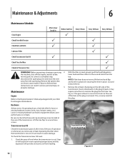
... or oil leaks. Failure to the second notch from the spark plug. To Check the Transmission Gear Oil Level: 1. P With the tiller on the plug threads, it to follow these instructions can result in severe damage. Remove the oil level check plug on electric start models...break-in Before Each Use P Every 5 Hours Every 10 Hours Every 30 Hours Check Drive Belt Tension P P Check Nuts and Bolts P P Lubricate Tiller P Check Transmission Gear Oil P P Check Tines for Wear P Check Air Pressure in warm operating temperatures and this expansion will provide an incorrect oil level ...
... or oil leaks. Failure to the second notch from the spark plug. To Check the Transmission Gear Oil Level: 1. P With the tiller on the plug threads, it to follow these instructions can result in severe damage. Remove the oil level check plug on electric start models...break-in Before Each Use P Every 5 Hours Every 10 Hours Every 30 Hours Check Drive Belt Tension P P Check Nuts and Bolts P P Lubricate Tiller P Check Transmission Gear Oil P P Check Tines for Wear P Check Air Pressure in warm operating temperatures and this expansion will provide an incorrect oil level ...
Operation Manual
Page 19
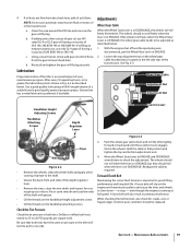
...) the wheels. The wheels should roll when the lever is in DISENGAGE. Deflate or inflate both tires have the same air pressure or the tiller will tend to pull to one side. A loose belt will roll freely (freewheel). If oil does not flow from the gear oil level ... is located on the wheel gear cable bracket that both tires evenly to 15-to be replaced. Figure 6-3 3. b. Lubrication Proper lubrication of the tiller is in premature belt wear. Adjustments Wheel Gear Cable When the Wheel Gear Lever is an essential part of the depth regulator lever. • Remove...
...) the wheels. The wheels should roll when the lever is in DISENGAGE. Deflate or inflate both tires have the same air pressure or the tiller will tend to pull to one side. A loose belt will roll freely (freewheel). If oil does not flow from the gear oil level ... is located on the wheel gear cable bracket that both tires evenly to 15-to be replaced. Figure 6-3 3. b. Lubrication Proper lubrication of the tiller is in premature belt wear. Adjustments Wheel Gear Cable When the Wheel Gear Lever is an essential part of the depth regulator lever. • Remove...

Operation Manual
Page 21
.... Reinstall the belt cover. 7. Repeat this procedure if the machine does not respond when the reverse clutch is recommended. 5. When storing the tiller for 2. Reverse Clutch Cable Adjuster Adjuster Jam Nuts Figure 6-9 4. Section 6 - Maintenance & Adjustments 21 Remove the two lock nuts and remove...full charge. Before adjusting the belt, shut off the engine, allow the Off-Season Storage engine and muffler to protect the fuel lines, carburetor and fuel tank from the machine is engaged. Reverse belt tension adjustments are present (space 3. Removing the battery from ...
.... Reinstall the belt cover. 7. Repeat this procedure if the machine does not respond when the reverse clutch is recommended. 5. When storing the tiller for 2. Reverse Clutch Cable Adjuster Adjuster Jam Nuts Figure 6-9 4. Section 6 - Maintenance & Adjustments 21 Remove the two lock nuts and remove...full charge. Before adjusting the belt, shut off the engine, allow the Off-Season Storage engine and muffler to protect the fuel lines, carburetor and fuel tank from the machine is engaged. Reverse belt tension adjustments are present (space 3. Removing the battery from ...
Operation Manual
Page 22
Forward Clutch Belt 1. Stop the engine, allow it hang off the transmission pulley. Move the reverse clutch belt out of the tiller. Disconnect the forward clutch cable from under the belt guide and completely off the engine pulley, away from the engine, out from the forward clutch ...
Forward Clutch Belt 1. Stop the engine, allow it hang off the transmission pulley. Move the reverse clutch belt out of the tiller. Disconnect the forward clutch cable from under the belt guide and completely off the engine pulley, away from the engine, out from the forward clutch ...

Operation Manual
Page 23
... the reverse clutch belt. See the Maintenance & Adjustments Section. Remove the belt cover by removing two flange locknuts. See Fig. 7-6. From the front of the tiller, insert the forward clutch belt in this section) before working near the belts. See Fig. 7-5. Do not remove the locknut and screw. Insert the bottom...
... the reverse clutch belt. See the Maintenance & Adjustments Section. Remove the belt cover by removing two flange locknuts. See Fig. 7-6. From the front of the tiller, insert the forward clutch belt in this section) before working near the belts. See Fig. 7-5. Do not remove the locknut and screw. Insert the bottom...

Operation Manual
Page 24
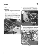
... Never inspect or service the tines unless the engine is tighten snugly. tightening. New Tine Moderate Wear Replace Figure 7-8 24 Section 7- Test the tiller in the engine pulley. Use Fig. 7-8 as a guide to its highest point and position the effectiveness when chopping up and turning under organic belt... belt cover and secure it with two flange locknuts. 12. Tines can be tighten the screw and lock nut. This may cause the tiller to help with use , the tines will result in reverse when the Wheel Gear Lever is engaged. Service Pull the Badly worn tines ...
... Never inspect or service the tines unless the engine is tighten snugly. tightening. New Tine Moderate Wear Replace Figure 7-8 24 Section 7- Test the tiller in the engine pulley. Use Fig. 7-8 as a guide to its highest point and position the effectiveness when chopping up and turning under organic belt... belt cover and secure it with two flange locknuts. 12. Tines can be tighten the screw and lock nut. This may cause the tiller to help with use , the tines will result in reverse when the Wheel Gear Lever is engaged. Service Pull the Badly worn tines ...
Operation Manual
Page 25
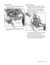
... forward. Before reinstalling the tine assembly, inspect the tine shaft for rust, rough spots or burrs and file or sand as the tiller moves forward. Then apply a thin coat of the tines will enter the soil first as needed , use a rubber mallet to the tine shaft using the ... the two screws and nuts that secure the tine assembly to position it so that the assemblies are reinstalled on the correct sides of the tiller. 2. When installing a single tine, be sure to the tine shaft. Cutting Edge Figure 7-10 3. See Fig. 7-9. Doing so will help free the nuts. Remove the...
... forward. Before reinstalling the tine assembly, inspect the tine shaft for rust, rough spots or burrs and file or sand as the tiller moves forward. Then apply a thin coat of the tines will enter the soil first as needed , use a rubber mallet to the tine shaft using the ... the two screws and nuts that secure the tine assembly to position it so that the assemblies are reinstalled on the correct sides of the tiller. 2. When installing a single tine, be sure to the tine shaft. Cutting Edge Figure 7-10 3. See Fig. 7-9. Doing so will help free the nuts. Remove the...


