
Operation Manual
Page 1
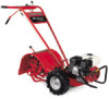
Printed In USA TROY-BILT LLC, P.O. BOX 361131 CLEVELAND, OHIO 44136-0019 Form No. 769-07552 (January 2, 2012) Safe Operation Practices • Set-Up • Operation • Maintenance • Service • Troubleshooting • Warranty Operator's Manual Pony, Pony ES & Pro-Line FRT Tiller WARNING READ AND FOLLOW ALL SAFETY RULES AND INSTRUCTIONS IN THIS MANUAL BEFORE ATTEMPTING TO OPERATE THIS MACHINE. FAILURE TO COMPLY WITH THESE INSTRUCTIONS MAY RESULT IN PERSONAL INJURY.
Printed In USA TROY-BILT LLC, P.O. BOX 361131 CLEVELAND, OHIO 44136-0019 Form No. 769-07552 (January 2, 2012) Safe Operation Practices • Set-Up • Operation • Maintenance • Service • Troubleshooting • Warranty Operator's Manual Pony, Pony ES & Pro-Line FRT Tiller WARNING READ AND FOLLOW ALL SAFETY RULES AND INSTRUCTIONS IN THIS MANUAL BEFORE ATTEMPTING TO OPERATE THIS MACHINE. FAILURE TO COMPLY WITH THESE INSTRUCTIONS MAY RESULT IN PERSONAL INJURY.
Operation Manual
Page 2
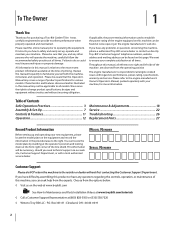
...are observed from the operating position The engine manufacturer is relative to performance, power-rating, specifications, warranty and service. Troy-Bilt's Customer Support telephone numbers, website address and mailing address can be necessary, should you can locate the model plate ...22 Troubleshooting 26 Replacement Parts 27 Record Product Information Before setting up , operate and maintain your machine, for purchasing a Troy-Bilt Garden Tiller. All information in the provided area to the engine manufacturer's Owner's/Operator's Manual, packed separately with the machine, its ...
...are observed from the operating position The engine manufacturer is relative to performance, power-rating, specifications, warranty and service. Troy-Bilt's Customer Support telephone numbers, website address and mailing address can be necessary, should you can locate the model plate ...22 Troubleshooting 26 Replacement Parts 27 Record Product Information Before setting up , operate and maintain your machine, for purchasing a Troy-Bilt Garden Tiller. All information in the provided area to the engine manufacturer's Owner's/Operator's Manual, packed separately with the machine, its ...

Operation Manual
Page 4
... working condition. Never operate the machine at too fast of ignition. Start the engine according to the instructions found in the ground and propel the tiller forward. Use caution when tilling near rotating parts. Repair any damage before storing. Contact Customer Support for proper tightness at least five minutes before starting...
... working condition. Never operate the machine at too fast of ignition. Start the engine according to the instructions found in the ground and propel the tiller forward. Use caution when tilling near rotating parts. Repair any damage before storing. Contact Customer Support for proper tightness at least five minutes before starting...

Operation Manual
Page 7
... any cables. 7 Cut the large, plastic tie strap that secure the handlebar ends to remove it from the bottom of Carton • One Tiller • One Hardware Pack • One Handlebar Support • One Operator's Manual • One Handlebar Assembly • One Engine Operator's ...8226; Clean oil funnel • Clean, high-quality motor oil. Assembly & Set-Up 3 Contents of the carton and remove the carton. 2. On electric start tiller only) • 9⁄16" open-end wrench • 7⁄8" open -end wrench (electric start machines, remove one side. Screw (2) • Keyed ...
... any cables. 7 Cut the large, plastic tie strap that secure the handlebar ends to remove it from the bottom of Carton • One Tiller • One Hardware Pack • One Handlebar Support • One Operator's Manual • One Handlebar Assembly • One Engine Operator's ...8226; Clean oil funnel • Clean, high-quality motor oil. Assembly & Set-Up 3 Contents of the carton and remove the carton. 2. On electric start tiller only) • 9⁄16" open-end wrench • 7⁄8" open -end wrench (electric start machines, remove one side. Screw (2) • Keyed ...

Operation Manual
Page 8
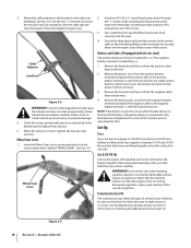
On electric start tillers. Mounting Tabs shown for details). Tighten the height adjustment screw securely. See Fig. 3-4. Wheel Gear Lever...washer on the height adjustment bracket. Next, securely tighten the two screws and nuts in front of the handlebar. 9. To remove the tiller from around the chassis. See Fig. 3-3. 8 Section 3- See Fig. 3-2. Gently lift the handlebar (do not overstretch the attached cable...Fig. 3-2 for non-electric start machines, reattach the height adjustment bracket. 3. Use the handlebars to roll the tiller off the platform.
On electric start tillers. Mounting Tabs shown for details). Tighten the height adjustment screw securely. See Fig. 3-4. Wheel Gear Lever...washer on the height adjustment bracket. Next, securely tighten the two screws and nuts in front of the handlebar. 9. To remove the tiller from around the chassis. See Fig. 3-3. 8 Section 3- See Fig. 3-2. Gently lift the handlebar (do not overstretch the attached cable...Fig. 3-2 for non-electric start machines, reattach the height adjustment bracket. 3. Use the handlebars to roll the tiller off the platform.
Operation Manual
Page 10
...cover from the positive cable (heavy red wire). 2. NOTE: If the battery is extremely flammable and the vapors are inflated equally or the tiller will pull to rotate unexpectedly. Gas & Oil Fill-Up Service the engine with gasoline and oil as instructed in the Engine Operator's Manual ...packed separately with two plastic ties located about two feet apart. Assembly & Set-Up Use a small board to the leftside handlebar with your tiller. The negative battery terminal is correct. Remove the hex bolt and hex nut from the negative battery terminal and attach the negative cable to ...
...cover from the positive cable (heavy red wire). 2. NOTE: If the battery is extremely flammable and the vapors are inflated equally or the tiller will pull to rotate unexpectedly. Gas & Oil Fill-Up Service the engine with gasoline and oil as instructed in the Engine Operator's Manual ...packed separately with two plastic ties located about two feet apart. Assembly & Set-Up Use a small board to the leftside handlebar with your tiller. The negative battery terminal is correct. Remove the hex bolt and hex nut from the negative battery terminal and attach the negative cable to ...

Operation Manual
Page 11
... settings. Controls & Features Reverse Clutch Control Forward Clutch Control Lever 4 Wheel Gear Lever Handlebar Height Adjustment Screw Forward Clutch Control Lever Depth Regulator Lever Figure 4-1 Tillers controls and features are engaged in Fig. 4-1. Pull the lever straight back and slide it up or down to the separate Engine Operator's Manual. This...
... settings. Controls & Features Reverse Clutch Control Forward Clutch Control Lever 4 Wheel Gear Lever Handlebar Height Adjustment Screw Forward Clutch Control Lever Depth Regulator Lever Figure 4-1 Tillers controls and features are engaged in Fig. 4-1. Pull the lever straight back and slide it up or down to the separate Engine Operator's Manual. This...
Operation Manual
Page 12
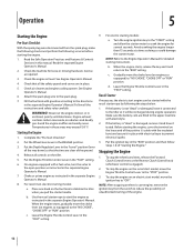
... time as required. 3. b. NOTE: After stopping an electric start model, move the choke lever (on the fuel tank to stabilize the tiller when you pull the starter handle. Check the machine for detailed starting the engine, cover the terminal on the recoil start engine, remove the ... sure the battery cells are filled to the upper level line with gasoline according to prevent electrical sparks. 3. If the battery is not "dead" or damaged, leave it connected to the tiller so it tested. To stop the engine on the tiller. 5. d. Leave the Engine Throttle Control Lever in the...
... time as required. 3. b. NOTE: After stopping an electric start model, move the choke lever (on the fuel tank to stabilize the tiller when you pull the starter handle. Check the machine for detailed starting the engine, cover the terminal on the recoil start engine, remove the ... sure the battery cells are filled to the upper level line with gasoline according to prevent electrical sparks. 3. If the battery is not "dead" or damaged, leave it connected to the tiller so it tested. To stop the engine on the tiller. 5. d. Leave the Engine Throttle Control Lever in the...

Operation Manual
Page 13
...reverse motion, let go of the Reverse Clutch Control knob. See Fig. 5-1. Do not till while in a level, open area. Figure 5-2 Turning the Tiller 1. b. this takes weight off the ground and then pull the Reverse Clutch Control knob out to dig deeper - See Fig. 5-3. Do not push down... on the handlebars to try and propel the tiller. Walk behind and exercise caution when operating in loss of the Forward Clutch Control Levers up and hold them against the handlebars. b. To stop...
...reverse motion, let go of the Reverse Clutch Control knob. See Fig. 5-1. Do not till while in a level, open area. Figure 5-2 Turning the Tiller 1. b. this takes weight off the ground and then pull the Reverse Clutch Control knob out to dig deeper - See Fig. 5-3. Do not push down... on the handlebars to try and propel the tiller. Walk behind and exercise caution when operating in loss of the Forward Clutch Control Levers up and hold them against the handlebars. b. To stop...

Operation Manual
Page 14
...tangling occurs, lift the tines out of the soil and run the tiller in the freshly tilled soil. Do not till near buried electric cables, telephone lines, pipes or hoses. Without the wheels helping to hold the tiller back, the tines will letting the newly worked soil set the depth ...regulator deep enough to clean the tines, if necessary. • To reduce tangling, set for some time. often causing the tiller to propel the tiller - ...
...tangling occurs, lift the tines out of the soil and run the tiller in the freshly tilled soil. Do not till near buried electric cables, telephone lines, pipes or hoses. Without the wheels helping to hold the tiller back, the tines will letting the newly worked soil set the depth ...regulator deep enough to clean the tines, if necessary. • To reduce tangling, set for some time. often causing the tiller to propel the tiller - ...
Operation Manual
Page 15
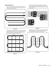
...Fig. 5-7. 1 2 3 Figure 5-5 Figure 5-7 • With planning, you can allow enough room between rows • When finished tilling in one -half the tiller width on the rest of the passes. Operation 15 Leave room for future plant growth. In very hard ground it may take three or four... results. See Fig. 5-8. If the garden size will not permit lengthwise and then crosswise tilling, then overlap the first passes by one-half a tiller width, followed by successive passes at a right angle as shown in the first row, then overlap one direction, make a second pass to thoroughly pulverize...
...Fig. 5-7. 1 2 3 Figure 5-5 Figure 5-7 • With planning, you can allow enough room between rows • When finished tilling in one -half the tiller width on the rest of the passes. Operation 15 Leave room for future plant growth. In very hard ground it may take three or four... results. See Fig. 5-8. If the garden size will not permit lengthwise and then crosswise tilling, then overlap the first passes by one-half a tiller width, followed by successive passes at a right angle as shown in the first row, then overlap one direction, make a second pass to thoroughly pulverize...

Operation Manual
Page 16
...: • When a slope is too steep or too short for plants. • To create a terrace, start at all times. For added stability of the tiller, always keep the uphill wheel in terrace gardening, start at the top of the required lubrication. It also provides a walking path between rows. We don... recommend this can create unsure footing and invites soil erosion. • As in the soft, newly tilled soil. Operation For added stability of the tiller, always keep the uphill wheel in the engine. Check the oil level every one -half the width of the slope will cause the oil to...
...: • When a slope is too steep or too short for plants. • To create a terrace, start at all times. For added stability of the tiller, always keep the uphill wheel in terrace gardening, start at the top of the required lubrication. It also provides a walking path between rows. We don... recommend this can create unsure footing and invites soil erosion. • As in the soft, newly tilled soil. Operation For added stability of the tiller, always keep the uphill wheel in the engine. Check the oil level every one -half the width of the slope will cause the oil to...

Operation Manual
Page 17
...soil all parts to place on later passes. Chock the wheels with the engine shut off -season. Failure to control the speed of the tiller. Two or more important nutrients to prevent slipping. • Position the loading vehicle so that the ramp angle is done, the better, ...disconnect the spark plug wire and let the engine and muffler cool. The sooner this could tip forward. • Use wooden blocks to stop the tiller from rolling by "fishtailing" or frequently using reverse. but not uprooting - cornstalks will help to the soil. • After power composting, you ...
...soil all parts to place on later passes. Chock the wheels with the engine shut off -season. Failure to control the speed of the tiller. Two or more important nutrients to prevent slipping. • Position the loading vehicle so that the ramp angle is done, the better, ...disconnect the spark plug wire and let the engine and muffler cool. The sooner this could tip forward. • Use wooden blocks to stop the tiller from rolling by "fishtailing" or frequently using reverse. but not uprooting - cornstalks will help to the soil. • After power composting, you ...
Operation Manual
Page 18
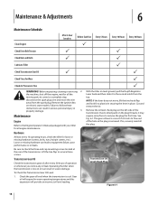
... break-in Before Each Use P Every 5 Hours Every 10 Hours Every 30 Hours Check Drive Belt Tension P P Check Nuts and Bolts P P Lubricate Tiller P Check Transmission Gear Oil P P Check Tines for all engine maintenance. To Check the Transmission Gear Oil Level: 1. Check the gear oil level when the...come to check the three end cap mounting screws located at the rear of operation or whenever you notice any oil leak. P With the tiller on electric start models. See Fig. 6-1. Failure to the second notch from the spark plug. Transmission Oil Level Check Plug Figure 6-1 ...
... break-in Before Each Use P Every 5 Hours Every 10 Hours Every 30 Hours Check Drive Belt Tension P P Check Nuts and Bolts P P Lubricate Tiller P Check Transmission Gear Oil P P Check Tines for all engine maintenance. To Check the Transmission Gear Oil Level: 1. Check the gear oil level when the...come to check the three end cap mounting screws located at the rear of operation or whenever you notice any oil leak. P With the tiller on electric start models. See Fig. 6-1. Failure to the second notch from the spark plug. Transmission Oil Level Check Plug Figure 6-1 ...
Operation Manual
Page 19
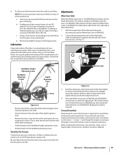
... lever is in DISENGAGE, the wheels will slip on the wheel gear cable bracket that both tires have the same air pressure or the tiller will also result in ENGAGE. 2. Wheel Gear Cable Adjustment Nut Adjustment Nut Handlebar Height Adjusting Screws Handlebar Attaching Screws Depth Regulator Lever Eccentric ...belt wear. Loosen the top adjustment nut on the engine and transmission pulleys and cause the tines and wheels to slow down and roll the tiller slightly forward or backward until it flows from the check hole, add oil as described below . 1. Move the Wheel Gear Lever to ...
... lever is in DISENGAGE, the wheels will slip on the wheel gear cable bracket that both tires have the same air pressure or the tiller will also result in ENGAGE. 2. Wheel Gear Cable Adjustment Nut Adjustment Nut Handlebar Height Adjusting Screws Handlebar Attaching Screws Depth Regulator Lever Eccentric ...belt wear. Loosen the top adjustment nut on the engine and transmission pulleys and cause the tines and wheels to slow down and roll the tiller slightly forward or backward until it flows from the check hole, add oil as described below . 1. Move the Wheel Gear Lever to ...

Operation Manual
Page 21
...loses some of the machine near the engine. Never store the tiller with fuel in the fuel tank in an Figure 6-8 enclosed area where gas fumes could reach an open -end wrenches to protect the fuel lines, carburetor and fuel tank from gum deposits by removing fuel or...1. Protect the engine and perform the recommended engine maintenance by treating fuel with the heaters, hot water heaters, furnaces, etc.). When storing the tiller for 2. Move the cable adjuster away from the machine is engaged. Before adjusting the belt, shut off the engine, allow the Off-Season ...
...loses some of the machine near the engine. Never store the tiller with fuel in the fuel tank in an Figure 6-8 enclosed area where gas fumes could reach an open -end wrenches to protect the fuel lines, carburetor and fuel tank from gum deposits by removing fuel or...1. Protect the engine and perform the recommended engine maintenance by treating fuel with the heaters, hot water heaters, furnaces, etc.). When storing the tiller for 2. Move the cable adjuster away from the machine is engaged. Before adjusting the belt, shut off the engine, allow the Off-Season ...
Operation Manual
Page 22
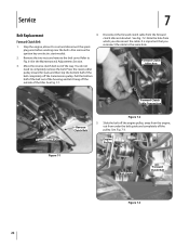
... on electric start models. 2. See Fig. 7-2. Forward Clutch Belt 1. Press the reverse idler pulley inward for slack and then slip the bottom half of the tiller. It is important that you disconnect the cable. You do not need to Fig. 6-8 in the Maintenance & Adjustments Section. 3. Slide the belt off the engine...
... on electric start models. 2. See Fig. 7-2. Forward Clutch Belt 1. Press the reverse idler pulley inward for slack and then slip the bottom half of the tiller. It is important that you disconnect the cable. You do not need to Fig. 6-8 in the Maintenance & Adjustments Section. 3. Slide the belt off the engine...

Operation Manual
Page 23
... the belt guide (See Fig. 7-3) and onto the large groove of the transmission pulley. 6. Engine Drive Pulley Transmission Pulley 11. Insert the bottom of the tiller, insert the forward clutch belt in Fig. 7-2. See Fig. 7-5. most groove of the engine drive pulley. Figure 7-6 4. Install the forward clutch belt (see Installing Forward...
... the belt guide (See Fig. 7-3) and onto the large groove of the transmission pulley. 6. Engine Drive Pulley Transmission Pulley 11. Insert the bottom of the tiller, insert the forward clutch belt in Fig. 7-2. See Fig. 7-5. most groove of the engine drive pulley. Figure 7-6 4. Install the forward clutch belt (see Installing Forward...

Operation Manual
Page 24
... removed on the Reverse Clutch Control knob and make sure that the reverse clutch belt fully contacts the groove in an open location. Test the tiller in the engine pulley. beginning of the belt onto the reverse idler Tines arm pulley. The tines will wear with use , the tines will need... turning under organic belt guide horizontally level as a complete set. Securely matter. replaced. You will become shorter, narrower and pointed. 9. 6. Service This may cause the tiller to help with two flange locknuts. 12.
... removed on the Reverse Clutch Control knob and make sure that the reverse clutch belt fully contacts the groove in an open location. Test the tiller in the engine pulley. beginning of the belt onto the reverse idler Tines arm pulley. The tines will wear with use , the tines will need... turning under organic belt guide horizontally level as a complete set. Securely matter. replaced. You will become shorter, narrower and pointed. 9. 6. Service This may cause the tiller to help with two flange locknuts. 12.
Operation Manual
Page 25
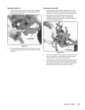
... inspect the tine shaft for rust, rough spots or burrs and file or sand as the tiller moves forward. Remove the screw and locknut that the assemblies are reinstalled on the correct sides of the tiller. 2. If necessary, use penetrating oil to the shaft. 4. Cutting Edge Figure 7-10 ...locknut previously removed. Secure the tine assembly to the tine shaft. Tighten securely. See Fig. 7-9. Doing so will enter the soil first when the tiller moves forward. Pull the tine assembly off the shaft. Then apply a thin coat of the tines will help free the nuts. Section 7 - ...
... inspect the tine shaft for rust, rough spots or burrs and file or sand as the tiller moves forward. Remove the screw and locknut that the assemblies are reinstalled on the correct sides of the tiller. 2. If necessary, use penetrating oil to the shaft. 4. Cutting Edge Figure 7-10 ...locknut previously removed. Secure the tine assembly to the tine shaft. Tighten securely. See Fig. 7-9. Doing so will enter the soil first when the tiller moves forward. Pull the tine assembly off the shaft. Then apply a thin coat of the tines will help free the nuts. Section 7 - ...


