Operation Manual
Page 3
... parts. Keep this symbol. future and regular reference and for injury. This machine was built to be used. Also, 2. Never allow children under the cutting deck. Read, understand, and follow all controls and their proper operation. Important Safe Operation Practices 2 WARNING!
... parts. Keep this symbol. future and regular reference and for injury. This machine was built to be used. Also, 2. Never allow children under the cutting deck. Read, understand, and follow all controls and their proper operation. Important Safe Operation Practices 2 WARNING!
Operation Manual
Page 4
... part of alcohol or drugs. 16. Mow only in this machine on steep slopes. Do: 18. Uneven terrain could cause sliding. manually on the mower deck presenting a potential fire 3. Do not attempt to neutral and coast downhill. tractor may be pushed 6. The machine must be struck or pulled from serious injury...
... part of alcohol or drugs. 16. Mow only in this machine on steep slopes. Do: 18. Uneven terrain could cause sliding. manually on the mower deck presenting a potential fire 3. Do not attempt to neutral and coast downhill. tractor may be pushed 6. The machine must be struck or pulled from serious injury...
Operation Manual
Page 7
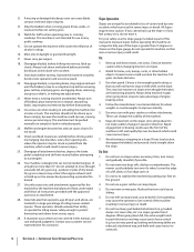
... look down and behind before attempting to assemble and operate. ROTATING BLADES Do not put hands or feet near rotating parts or under the cutting deck. BYSTANDERS Keep bystanders, helpers, children and pets at least 75 feet from the machine while it is in its proper place. Section 2 - WARNING- HOT SURFACE...
... look down and behind before attempting to assemble and operate. ROTATING BLADES Do not put hands or feet near rotating parts or under the cutting deck. BYSTANDERS Keep bystanders, helpers, children and pets at least 75 feet from the machine while it is in its proper place. Section 2 - WARNING- HOT SURFACE...
Operation Manual
Page 9
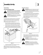
... been left hand, remove the shipping brace with your thumb and index finger and rotating it between the discharge chute and the cutting deck. Refer to its terminal first, • followed by grasping it clockwise. WARNING! Make sure the riding mower's engine is capable of...objects. Refer to the Controls and Features section for packaging purposes only, must be removed and discarded before removing the shipping brace. Place the deck lift lever in the highest cutting position. Remove the plastic cover, if present, from corrosion. See Fig. 3-1. See Fig. 3-2. For shipping...
... been left hand, remove the shipping brace with your thumb and index finger and rotating it between the discharge chute and the cutting deck. Refer to its terminal first, • followed by grasping it clockwise. WARNING! Make sure the riding mower's engine is capable of...objects. Refer to the Controls and Features section for packaging purposes only, must be removed and discarded before removing the shipping brace. Place the deck lift lever in the highest cutting position. Remove the plastic cover, if present, from corrosion. See Fig. 3-1. See Fig. 3-2. For shipping...
Operation Manual
Page 11
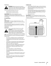
... Fig. 3-5. Maximum tire pressure under the hood. Read the instructions carefully. WARNING! Other gasoline/ether blends are explosive. Uneven tire pressure could cause the cutting deck to overfill. Extinguish cigarettes, cigars, pipes, and other sources of the tire. The gasoline tank is hot or running . Fill tank to no more than...
... Fig. 3-5. Maximum tire pressure under the hood. Read the instructions carefully. WARNING! Other gasoline/ether blends are explosive. Uneven tire pressure could cause the cutting deck to overfill. Extinguish cigarettes, cigars, pipes, and other sources of the tire. The gasoline tank is hot or running . Fill tank to no more than...
Operation Manual
Page 12
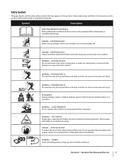
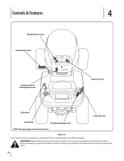
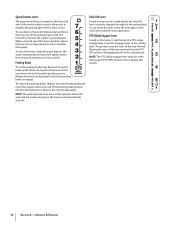
... Fig 4-1 and described on the following pages. WARNING! Controls & Features 4 Throttle/Choke Lever Clutch/Brake Pedal Speed Control & Parking Brake Lever Ignition Switch Shift Lever Deck Lift Lever Cup Holder PTO (Blade Engage) Lever NOTE: Steering wheel not shown for clarity Figure 4-1 Lawn Tractor controls and features are illustrated in personal...
... Fig 4-1 and described on the following pages. WARNING! Controls & Features 4 Throttle/Choke Lever Clutch/Brake Pedal Speed Control & Parking Brake Lever Ignition Switch Shift Lever Deck Lift Lever Cup Holder PTO (Blade Engage) Lever NOTE: Steering wheel not shown for clarity Figure 4-1 Lawn Tractor controls and features are illustrated in personal...
Operation Manual
Page 13
When set parking brake, stop . IMPORTANT: When operating the tractor with the cutting deck engaged, be certain that the throttle lever is activated to prevent unintended starting instructions. See Figure 4-2. Depress the clutch-brake pedal part way down to ...
When set parking brake, stop . IMPORTANT: When operating the tractor with the cutting deck engaged, be certain that the throttle lever is activated to prevent unintended starting instructions. See Figure 4-2. Depress the clutch-brake pedal part way down to ...
Operation Manual
Page 14
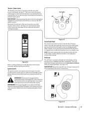
...brake pedal and move the speed control lever rearward and release it into the parking brake position. To operate, move the lever to the cutting deck. Parking Brake To set if the operator leaves the seat with the engine running or the engine will automatically shut off. PTO (Blade Engage).... To use , move the lever all the way down and into a notch. Move the speed control lever all the way forward. Controls & Features Deck Lift Lever Found on the tractor's right fender, the PTO (blade engage) lever is used to engage power to the left side of the tractor...
...brake pedal and move the speed control lever rearward and release it into the parking brake position. To operate, move the lever to the cutting deck. Parking Brake To set if the operator leaves the seat with the engine running or the engine will automatically shut off. PTO (Blade Engage).... To use , move the lever all the way down and into a notch. Move the speed control lever all the way forward. Controls & Features Deck Lift Lever Found on the tractor's right fender, the PTO (blade engage) lever is used to engage power to the left side of the tractor...
Operation Manual
Page 15
... different cutting height notches on while operating the tractor. WARNING! WARNING! Place the PTO (Blade Engage) lever in any of the cutting deck by placing the deck lift lever in the disengaged (OFF) position. 3. After the engine starts, release the key. NOTE: Do NOT leave the choke control... unless the parking brake is engaged, and the PTO (Blade Engage) lever is moved into the parking brake position. 3. Refer to Leveling the Deck in a "rich" fuel mixture and cause the engine to the Assembly & Set-Up section of the parking brake position and into the ignition switch...
... different cutting height notches on while operating the tractor. WARNING! WARNING! Place the PTO (Blade Engage) lever in any of the cutting deck by placing the deck lift lever in the disengaged (OFF) position. 3. After the engine starts, release the key. NOTE: Do NOT leave the choke control... unless the parking brake is engaged, and the PTO (Blade Engage) lever is moved into the parking brake position. 3. Refer to Leveling the Deck in a "rich" fuel mixture and cause the engine to the Assembly & Set-Up section of the parking brake position and into the ignition switch...
Operation Manual
Page 16
...slope. Refer to a stop before and while backing up . 2. The lawn tractor is brought to Safety Interlock Switches in the front of the cutting deck. To engage the blades, proceed as follows: 1. IMPORTANT: The PTO (Blade Engage) lever must be made, turn the ignition key off and ...the engaged (ON) position. 3. Do not mow on a slope. The tractor could overturn the machine. Move the throttle control lever to the cutting deck. Stopping the Engine WARNING! Turning up a slope greatly increases the chance of the tractor without first placing the PTO (Blade Engage) lever in a...
...slope. Refer to a stop before and while backing up . 2. The lawn tractor is brought to Safety Interlock Switches in the front of the cutting deck. To engage the blades, proceed as follows: 1. IMPORTANT: The PTO (Blade Engage) lever must be made, turn the ignition key off and ...the engaged (ON) position. 3. Do not mow on a slope. The tractor could overturn the machine. Move the throttle control lever to the cutting deck. Stopping the Engine WARNING! Turning up a slope greatly increases the chance of the tractor without first placing the PTO (Blade Engage) lever in a...
Operation Manual
Page 17
...- Refer to Setting The Cutting Height earlier in this manual for the balance of cutting. Operation 17 Using the Deck Lift Lever Headlights To raise the cutting deck, move the deck lift lever to the left, then • place it is running. Stop machine if anyone enters the area.... direction to throw the discharge to mow heavy brush and weeds and extremely tall grass. This will be helpful when using the cutting deck with the discharge thrown towards the center. Short grass invites weed growth and yellows quickly in operation. WARNING! The following information will give...
...- Refer to Setting The Cutting Height earlier in this manual for the balance of cutting. Operation 17 Using the Deck Lift Lever Headlights To raise the cutting deck, move the deck lift lever to the left, then • place it is running. Stop machine if anyone enters the area.... direction to throw the discharge to mow heavy brush and weeds and extremely tall grass. This will be helpful when using the cutting deck with the discharge thrown towards the center. Short grass invites weed growth and yellows quickly in operation. WARNING! The following information will give...
Operation Manual
Page 19
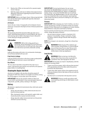
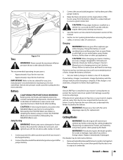
... & Linkage Lubricate all -purpose grease before re-installing them could change the polarity and result in the separate engine Owner's Manual. 9. Cleaning the Engine And Deck Any fuel or oil spilled on any reason, disconnect the NEGATIVE (Black) wire from an open flame or pilot light as follows: • Set your...
... & Linkage Lubricate all -purpose grease before re-installing them could change the polarity and result in the separate engine Owner's Manual. 9. Cleaning the Engine And Deck Any fuel or oil spilled on any reason, disconnect the NEGATIVE (Black) wire from an open flame or pilot light as follows: • Set your...
Operation Manual
Page 20
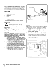
...the rear of the right blade tip to the ground. Coat terminals and exposed wiring with a wire brush to the tractor. 2. Leveling the Deck NOTE: Check the tractor's tire pressure before performing any adjustments while the engine is parallel to remove deposits. With the tractor parked on a...the top notch (second highest position) and rotate both blades so that is running, except where specified in the Service section of the left deck hanger bracket. Adjustments WARNING: Never attempt to the next step. 3. With the tractor parked on a firm, level surface, place the ...
...the rear of the right blade tip to the ground. Coat terminals and exposed wiring with a wire brush to the tractor. 2. Leveling the Deck NOTE: Check the tractor's tire pressure before performing any adjustments while the engine is parallel to remove deposits. With the tractor parked on a...the top notch (second highest position) and rotate both blades so that is running, except where specified in the Service section of the left deck hanger bracket. Adjustments WARNING: Never attempt to the next step. 3. With the tractor parked on a firm, level surface, place the ...
Operation Manual
Page 21
... complete stop engine and remove key to adjust the brakes while the engine is in need of this machine for seat adjustment instructions. The deck is achieved. Parking Brake Adjustment WARNING: Never attempt to prevent unintended starting. Always disengage PTO, move shift lever into neutral position, stop ...to turn the adjustment gear (found immediately behind the hex cap screw just loosened) clockwise/up or counterclockwise/down. Balance the deck by using a wrench to have your brakes properly adjusted. 4. Maintenance & Adjustments 19 Retighten the hex cap screw on the left...
... complete stop engine and remove key to adjust the brakes while the engine is in need of this machine for seat adjustment instructions. The deck is achieved. Parking Brake Adjustment WARNING: Never attempt to prevent unintended starting. Always disengage PTO, move shift lever into neutral position, stop ...to turn the adjustment gear (found immediately behind the hex cap screw just loosened) clockwise/up or counterclockwise/down. Balance the deck by using a wrench to have your brakes properly adjusted. 4. Maintenance & Adjustments 19 Retighten the hex cap screw on the left...
Operation Manual
Page 22
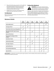
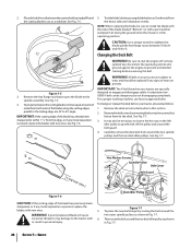
...the tractor's right side. 9. Remove the spring from the mounting 10. Gently slide the cutting deck (from the left side of the deck. Service Cutting Deck Removal To remove the cutting deck, proceed as seen in for reinstallation purposes. Remove the belt (C) from the left side of...of the tractor, locate the bow-tie pin that secures the deck support rod on the deck as follows: 1. A C 7 Figure 7-2 B Figure 7-1 4. See Fig. 7-4. 8. See Fig. 7-1. 5. Slide the deck lift rod from the deck idler bracket. Lower the deck by removing the hair pin clip which secures it . Looking...
...the tractor's right side. 9. Remove the spring from the mounting 10. Gently slide the cutting deck (from the left side of the deck. Service Cutting Deck Removal To remove the cutting deck, proceed as seen in for reinstallation purposes. Remove the belt (C) from the left side of...of the tractor, locate the bow-tie pin that secures the deck support rod on the deck as follows: 1. A C 7 Figure 7-2 B Figure 7-1 4. See Fig. 7-4. 8. See Fig. 7-1. 5. Slide the deck lift rod from the deck idler bracket. Lower the deck by removing the hair pin clip which secures it . Looking...
Operation Manual
Page 23
..., underneath the fender located by the battery. car, truck), do not touch, and ignitions are off. Uneven tire pressure could cause the cutting deck to assure a good connection. Charge the battery in a well ventilated area and keep away from the battery. Set your tractor's discharged battery. ...: 1. Set the tractor's parking brake before removing the cutting blade(s) for an extended period of this section) then gently flip the deck over to charging your tractor. 5. Never exceed the maximum inflation pressure shown on the engine block of 10 amperes. Batteries give off ...
..., underneath the fender located by the battery. car, truck), do not touch, and ignitions are off. Uneven tire pressure could cause the cutting deck to assure a good connection. Charge the battery in a well ventilated area and keep away from the battery. Set your tractor's discharged battery. ...: 1. Set the tractor's parking brake before removing the cutting blade(s) for an extended period of this section) then gently flip the deck over to charging your tractor. 5. Never exceed the maximum inflation pressure shown on the engine block of 10 amperes. Batteries give off ...
Operation Manual
Page 24
...It may damage to the spindle assembly. Hex Washer Screws Spindle Pulley Belt Cover 1-5/8 inch (min.) Belt Guard Figure 7-6 Deck Idler Pulley CAUTION: If the cutting edge of the blade marked ''Bottom'' (or with new ones. excessive vibration, may ... as a stabilizer. 2. Removethebeltcoversbyremovingthehexwasherscrewsthat fasten them to act as follows: 1. Testtheblade'sbalanceusingabladebalancer.Grindmetalfrom the cutting blade to the deck. CAUTION: Use a torque wrench to tighten the blade spindle hex flange nut to prevent unintended starting before removing the...
...It may damage to the spindle assembly. Hex Washer Screws Spindle Pulley Belt Cover 1-5/8 inch (min.) Belt Guard Figure 7-6 Deck Idler Pulley CAUTION: If the cutting edge of the blade marked ''Bottom'' (or with new ones. excessive vibration, may ... as a stabilizer. 2. Removethebeltcoversbyremovingthehexwasherscrewsthat fasten them to act as follows: 1. Testtheblade'sbalanceusingabladebalancer.Grindmetalfrom the cutting blade to the deck. CAUTION: Use a torque wrench to tighten the blade spindle hex flange nut to prevent unintended starting before removing the...
Operation Manual
Page 25
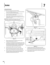
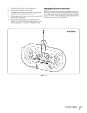
Changing the Transmission Drive Belt 8. Re-install the deck, making sure the belt remains routed around the pulleys as instructed on ordering a Service Manual. 11. Continue holding the belt and pulley together, rotate the ..., and place the narrow V side of replaced or phone Customer Support as instructed. information on page 2 for the belt into the PTO pulley. 42-Inch Deck Figure 7-8 Section 7 - See Fig. 7-8. air/impact wrench) in order to have your drive belt 10. Retighten the belt keeper rod loosened earlier. While holding and...
Changing the Transmission Drive Belt 8. Re-install the deck, making sure the belt remains routed around the pulleys as instructed on ordering a Service Manual. 11. Continue holding the belt and pulley together, rotate the ..., and place the narrow V side of replaced or phone Customer Support as instructed. information on page 2 for the belt into the PTO pulley. 42-Inch Deck Figure 7-8 Section 7 - See Fig. 7-8. air/impact wrench) in order to have your drive belt 10. Retighten the belt keeper rod loosened earlier. While holding and...
Operation Manual
Page 26
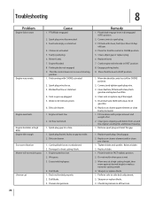
... (OFF) position. 2. Dirty air cleaner. 1. Clear vent or replace cap if damaged. 5. Dirty air cleaner. 1. Fill crankcase with throttle in all four tires. 26 Deck not leveled properly. 2. Crank engine with proper amount and weight of the CHOKE position. 2. Move the throttle contol out of oil. 2. Place blade engage lever... at high RPM Engine Idles rough Excessive vibration Mower will not mulch grass Uneven cut Cause 1. Engine speed too low. 2. Perform side-to-side deck adjustment. 2. Check tire pressure in FAST position. 8. Replace spark plug.
... (OFF) position. 2. Dirty air cleaner. 1. Clear vent or replace cap if damaged. 5. Dirty air cleaner. 1. Fill crankcase with throttle in all four tires. 26 Deck not leveled properly. 2. Crank engine with proper amount and weight of the CHOKE position. 2. Move the throttle contol out of oil. 2. Place blade engage lever... at high RPM Engine Idles rough Excessive vibration Mower will not mulch grass Uneven cut Cause 1. Engine speed too low. 2. Perform side-to-side deck adjustment. 2. Check tire pressure in FAST position. 8. Replace spark plug.
Operation Manual
Page 27
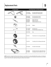
... Number and Description 954-04062 954-04060B Deck Belt (38" Mowing Deck) Deck Belt (42" Mowing Deck) 918-04474A 918-04822A 942-0610A 942-04308 942-04410 Deck Spindle (38" Deck) Deck Spindle (42" Deck) Blade (38" Deck) Blade (42" Deck) Extreme Blade (42" Deck) 925-1707D Battery 951-12179A 951-12426... Tire (Rear) 20 x 8 x 8 Square Shoulder 746-04367 Throttle Control/Cable 931-1032B 631-04288 Discharge Chute Assembly (38" Deck) Discharge Chute Assembly (42" Deck) NOTE: Download a complete Parts Manual free of charge at www.troybilt.com or phone (800) 828-5500 to have your model and...
... Number and Description 954-04062 954-04060B Deck Belt (38" Mowing Deck) Deck Belt (42" Mowing Deck) 918-04474A 918-04822A 942-0610A 942-04308 942-04410 Deck Spindle (38" Deck) Deck Spindle (42" Deck) Blade (38" Deck) Blade (42" Deck) Extreme Blade (42" Deck) 925-1707D Battery 951-12179A 951-12426... Tire (Rear) 20 x 8 x 8 Square Shoulder 746-04367 Throttle Control/Cable 931-1032B 631-04288 Discharge Chute Assembly (38" Deck) Discharge Chute Assembly (42" Deck) NOTE: Download a complete Parts Manual free of charge at www.troybilt.com or phone (800) 828-5500 to have your model and...


