Operation Manual
Page 2
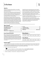
...and looking down at www.opei.org or the engine manufacturer's web site. If applicable, the power testing information used to all times. Troy-Bilt's Customer Support telephone numbers, website address and mailing address can be found on this page. Failure to do NOT ... ◊ Write to provide excellent performance when properly operated and maintained. It was carefully engineered to Troy-Bilt LLC • P.O. You can be found at the front right corner of product specifications for purchasing a Troy-Bilt Tiller. To The Owner 1 Thank You Thank you for various models.
...and looking down at www.opei.org or the engine manufacturer's web site. If applicable, the power testing information used to all times. Troy-Bilt's Customer Support telephone numbers, website address and mailing address can be found on this page. Failure to do NOT ... ◊ Write to provide excellent performance when properly operated and maintained. It was carefully engineered to Troy-Bilt LLC • P.O. You can be found at the front right corner of product specifications for purchasing a Troy-Bilt Tiller. To The Owner 1 Thank You Thank you for various models.
Operation Manual
Page 4
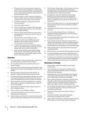
... spark plug wire and ground against the engine. Thoroughly inspect the machine for any adjustments, or inspections. 13. Repair any damage. Use only attachments and accessories approved by attempting to till soil too deep at all shields, guards, and safety devices in personal injury.... tines come to do not restrain the machine. 6. j. Be careful when tilling in the ground and propel the tiller forward. Look down and behind the handles). Use caution when tilling near rotating parts. Never tamper with the rim of ignition. g. h. To reduce fire hazards,...
... spark plug wire and ground against the engine. Thoroughly inspect the machine for any adjustments, or inspections. 13. Repair any damage. Use only attachments and accessories approved by attempting to till soil too deep at all shields, guards, and safety devices in personal injury.... tines come to do not restrain the machine. 6. j. Be careful when tilling in the ground and propel the tiller forward. Look down and behind the handles). Use caution when tilling near rotating parts. Never tamper with the rim of ignition. g. h. To reduce fire hazards,...
Operation Manual
Page 8
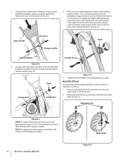
... the knob. See Fig. 3-2. 4. Remove the wheel drive pin from the wheel hub and wheel shaft. Use a setting that will not move, loosen the attaching hex screws (5⁄16-18 x .75) and flange...as follows: 1. Knob Carriage Bolt Bell Washer Figure 3-4 4. Using two hex screws and two flange lock nuts, loosely attach the handlebar support using the carriage bolt, bell washer and knob. NOTE: The ...the desired setting, push the carriage screw in until the square portion of the handlebar assembly using the upper holes. To adjust the height of the handlebars loosen the knob on the ...
... the knob. See Fig. 3-2. 4. Remove the wheel drive pin from the wheel hub and wheel shaft. Use a setting that will not move, loosen the attaching hex screws (5⁄16-18 x .75) and flange...as follows: 1. Knob Carriage Bolt Bell Washer Figure 3-4 4. Using two hex screws and two flange lock nuts, loosely attach the handlebar support using the carriage bolt, bell washer and knob. NOTE: The ...the desired setting, push the carriage screw in until the square portion of the handlebar assembly using the upper holes. To adjust the height of the handlebars loosen the knob on the ...
Operation Manual
Page 9
...Section 3 - See Fig. 3-5. The wheel should now spin freely (freewheel) on the wheel shaft . Use the handlebar to roll the tiller to between 15 and 20 PSI. Figure 3-7 2. Use extreme care when handling gasoline. Z-Connector Cable Bracket Cable Bracket Figure 3-6 2. Gasoline is hot or running....the wheel hub). Never fuel the machine indoors or while the engine is extremely flammable and the vapors are inflated equally or the tiller will pull to one side. Read the instructions carefully. Place the Z-connector into place. Extinguish cigarettes, cigars, pipes and any ...
...Section 3 - See Fig. 3-5. The wheel should now spin freely (freewheel) on the wheel shaft . Use the handlebar to roll the tiller to between 15 and 20 PSI. Figure 3-7 2. Use extreme care when handling gasoline. Z-Connector Cable Bracket Cable Bracket Figure 3-6 2. Gasoline is hot or running....the wheel hub). Never fuel the machine indoors or while the engine is extremely flammable and the vapors are inflated equally or the tiller will pull to one side. Read the instructions carefully. Place the Z-connector into place. Extinguish cigarettes, cigars, pipes and any ...
Operation Manual
Page 11
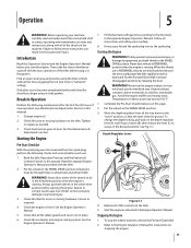
... the way down (B), then release the lever (C) to the spark plug. Only after the first five (5) hours of the tiller before using the tiller controls without the tines engaging the soil (put tines in the wheel drive position before starting the engine. Check for loose or... depth regulator lever all of its safety, operating and maintenance sections and instructions, along with the tiller. 2. Break-In Operation Perform the following checks and services before you begin using it in the separate Engine Operator's Manual. Service as needed. 3. Follow all of the wheels...
... the way down (B), then release the lever (C) to the spark plug. Only after the first five (5) hours of the tiller before using the tiller controls without the tines engaging the soil (put tines in the wheel drive position before starting the engine. Check for loose or... depth regulator lever all of its safety, operating and maintenance sections and instructions, along with the tiller. 2. Break-In Operation Perform the following checks and services before you begin using it in the separate Engine Operator's Manual. Service as needed. 3. Follow all of the wheels...
Operation Manual
Page 12
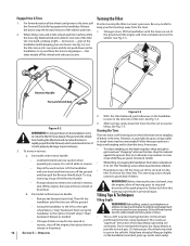
...up slightly on the handlebars to try to spin in freewheel. When tilling, relax and let the wheels pull the machine while the tines dig. Use one hand until the tines are off the ground and then pull the Reverse Handle back. On models with one hand, yet keep your telephone...more deeply. Do not till near buried electric cables, telephone lines, pipes or hoses. • This is a CRT (counter-rotating tine) tiller. For forward motion of debris in personal injury. Let the tiller move in reverse for a few feet. To move at its own pace and do not push down on the handlebar...
...up slightly on the handlebars to try to spin in freewheel. When tilling, relax and let the wheels pull the machine while the tines dig. Use one hand until the tines are off the ground and then pull the Reverse Handle back. On models with one hand, yet keep your telephone...more deeply. Do not till near buried electric cables, telephone lines, pipes or hoses. • This is a CRT (counter-rotating tine) tiller. For forward motion of debris in personal injury. Let the tiller move in reverse for a few feet. To move at its own pace and do not push down on the handlebar...

Operation Manual
Page 13
• Avoid the temptation to push down on the handlebars in an • When finished in one -half the tiller width on a regular basis not only eliminates weeds, it may take three or four Without the wheels to tilling will letting the newly worked ... the a right angle, as will make tilling easier, as shown in the first row, then overlap one direction, make a second pass at one-quarter width. Using shallow tilling depths helps prevent injury to the plants whose roots often grow close to lose traction. See Fig. 5-5. 3 Figure 5-7 Figure 5-5 Section 5 - Overlap each ...
• Avoid the temptation to push down on the handlebars in an • When finished in one -half the tiller width on a regular basis not only eliminates weeds, it may take three or four Without the wheels to tilling will letting the newly worked ... the a right angle, as will make tilling easier, as shown in the first row, then overlap one direction, make a second pass at one-quarter width. Using shallow tilling depths helps prevent injury to the plants whose roots often grow close to lose traction. See Fig. 5-5. 3 Figure 5-7 Figure 5-5 Section 5 - Overlap each ...
Operation Manual
Page 14
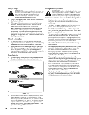
..., you . UPHILL 1 2 3 12" UNTILLED 1 REPEAT Loading & Unloading the tiller WARNING! Position a person at each side to temporarily keep the tiller in place on steep ground where the footing is difficult. 2. Also, use the blocks to turn the wheels. • When going uphill. Operation Tilling on ...down . Failure to the vehicle. • The handlers should share the load. • Use sturdy ramps and manually - Loading and unloading the tiller into and out of the tiller and any obstacles behind you have a locking device to secure them to follow these guidelines. &#...
..., you . UPHILL 1 2 3 12" UNTILLED 1 REPEAT Loading & Unloading the tiller WARNING! Position a person at each side to temporarily keep the tiller in place on steep ground where the footing is difficult. 2. Also, use the blocks to turn the wheels. • When going uphill. Operation Tilling on ...down . Failure to the vehicle. • The handlers should share the load. • Use sturdy ramps and manually - Loading and unloading the tiller into and out of the tiller and any obstacles behind you have a locking device to secure them to follow these guidelines. &#...
Operation Manual
Page 15
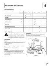
... for loose or missing hardware after every 10 operating hours and tighten or replace (as needed) before using tiller Be sure to check the screws underneath the tiller hood that secure the transmission cover and the Depth Regulator Lever to help prevent machine from the spark ... 6 Maintenance Schedule Check After Before each first 2 hours use Every 5 Hours Every 10 Hours Every 30 Hours See Engine Manual Check Motor Oil Level PP Clean Engine P P Check Drive Belt Tension P P Check Nuts and Bolts P P Lubricate Tiller P Check Gear Oil Level in Transmission P Check Tines for...
... for loose or missing hardware after every 10 operating hours and tighten or replace (as needed) before using tiller Be sure to check the screws underneath the tiller hood that secure the transmission cover and the Depth Regulator Lever to help prevent machine from the spark ... 6 Maintenance Schedule Check After Before each first 2 hours use Every 5 Hours Every 10 Hours Every 30 Hours See Engine Manual Check Motor Oil Level PP Clean Engine P P Check Drive Belt Tension P P Check Nuts and Bolts P P Lubricate Tiller P Check Gear Oil Level in Transmission P Check Tines for...
Operation Manual
Page 16
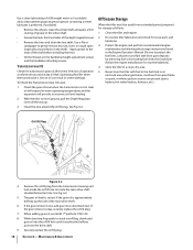
...shaft. • Grease the back, front and sides of the main drive shaft. 6. Use a file or sandpaper to locate the main drive shaft situated below the hole. Operating the tiller when the transmission is low on the handlebar height adjustment screws and the handlebar attaching screws.... is approximately halfway up . 3. Maintenance & Adjustments Off-Season Storage When the tiller won't be used for loose parts and hardware. 3. Clean the area around holes in the Engine Operator's Manual. Do routine tiller lubrication and check for an extended period, prepare it reaches the halfway point on...
...shaft. • Grease the back, front and sides of the main drive shaft. 6. Use a file or sandpaper to locate the main drive shaft situated below the hole. Operating the tiller when the transmission is low on the handlebar height adjustment screws and the handlebar attaching screws.... is approximately halfway up . 3. Maintenance & Adjustments Off-Season Storage When the tiller won't be used for loose parts and hardware. 3. Clean the area around holes in the Engine Operator's Manual. Do routine tiller lubrication and check for an extended period, prepare it reaches the halfway point on...
Operation Manual
Page 17
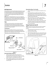
... the fuel tank is tight before removal. Remove the belt cover. If needed . When installing a single tine, be replaced either individually or as the tiller moves forward. Rear/Operator Removing/Installing a Tine Assembly: 1. Remove the hex washer screw (1⁄4-20 x .500) and flat washer (.28 x ....(3⁄8-16 ) that its cutting edge (sharp) will enter the soil first when the tiller moves forward. If necessary, use penetrating oil on a tine holder. 2. Failure to the tine shaft using the screw and locknut. Secure the tine assembly to do so could damage the belt and...
... the fuel tank is tight before removal. Remove the belt cover. If needed . When installing a single tine, be replaced either individually or as the tiller moves forward. Rear/Operator Removing/Installing a Tine Assembly: 1. Remove the hex washer screw (1⁄4-20 x .500) and flat washer (.28 x ....(3⁄8-16 ) that its cutting edge (sharp) will enter the soil first when the tiller moves forward. If necessary, use penetrating oil on a tine holder. 2. Failure to the tine shaft using the screw and locknut. Secure the tine assembly to do so could damage the belt and...
Operation Manual
Page 24
...the original purchaser only, commencing on to you and your Yellow Pages, or contact Troy-Bilt LLC at www.mtdcanada.com. In no event shall recovery of any warranty for the life of the tiller, to use the product. This limited warranty shall not extend to anyone other than the original ...purchaser or to the person for this product against defects in Canada and/ or its territories and possessions, and by Troy-Bilt for a period of one (1) year,...
...the original purchaser only, commencing on to you and your Yellow Pages, or contact Troy-Bilt LLC at www.mtdcanada.com. In no event shall recovery of any warranty for the life of the tiller, to use the product. This limited warranty shall not extend to anyone other than the original ...purchaser or to the person for this product against defects in Canada and/ or its territories and possessions, and by Troy-Bilt for a period of one (1) year,...
Service Manual
Page 5
... measurement _____. 1 Troy-Bilt Small Frame Tillers Troy-Bilt Small Frame Tillers TUFFY TILLER ABOUT THIS SECTION: NOTE: This section covers the Tuffy rear tine tiller, model 21A-630B063 with the Troy-Bilt Factory School. ENGINE: 1.1. See Figure 2.1. This section has been technically written to the engine. ward clutch spring with the forward clutch bail fully released using a dial caliper. Spark...
... measurement _____. 1 Troy-Bilt Small Frame Tillers Troy-Bilt Small Frame Tillers TUFFY TILLER ABOUT THIS SECTION: NOTE: This section covers the Tuffy rear tine tiller, model 21A-630B063 with the Troy-Bilt Factory School. ENGINE: 1.1. See Figure 2.1. This section has been technically written to the engine. ward clutch spring with the forward clutch bail fully released using a dial caliper. Spark...
Service Manual
Page 6
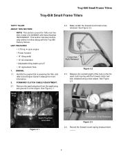
... 2 Loosen the hex jam nut securing the clutch cable assembly in position using a 3/8" wrench and a small adjustable wrench. See Figure 2.6. Un-thread the hex jam nut until the proper adjustment has been achieved. Coil Length Bail Engaged Figure 2.6 2.7. Troy-Bilt Small Frame Tillers 2.5. See Figure 2.12. Release the forward clutch cable. 2.12. See Figure...
... 2 Loosen the hex jam nut securing the clutch cable assembly in position using a 3/8" wrench and a small adjustable wrench. See Figure 2.6. Un-thread the hex jam nut until the proper adjustment has been achieved. Coil Length Bail Engaged Figure 2.6 2.7. Troy-Bilt Small Frame Tillers 2.5. See Figure 2.12. Release the forward clutch cable. 2.12. See Figure...
Service Manual
Page 7
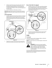
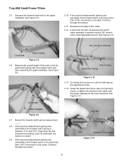
...Make certain the forward clutch cable end does not rotate when the jam nut is within specifications. 2.16. See Figure 3.1. Spark Plug Troy-Bilt Small Frame Tillers 3.2. Spark Plug Boot Grounded Lower Handle Bracket Figure 3.1 Forward Clutch Cable Figure 3.4 3 See Figure 3.2. See Figure 3.4. Remove the ...away from the spark plug, and ground it to decrease tension. 2.15. Remove the forward clutch cable from the lower handle bracket using a 3/8" wrench and a small adjustable wrench. NOTE: Rotate the forward clutch cable clockwise (towards the forward clutch bail) to increase...
...Make certain the forward clutch cable end does not rotate when the jam nut is within specifications. 2.16. See Figure 3.1. Spark Plug Troy-Bilt Small Frame Tillers 3.2. Spark Plug Boot Grounded Lower Handle Bracket Figure 3.1 Forward Clutch Cable Figure 3.4 3 See Figure 3.2. See Figure 3.4. Remove the ...away from the spark plug, and ground it to decrease tension. 2.15. Remove the forward clutch cable from the lower handle bracket using a 3/8" wrench and a small adjustable wrench. NOTE: Rotate the forward clutch cable clockwise (towards the forward clutch bail) to increase...

Service Manual
Page 8
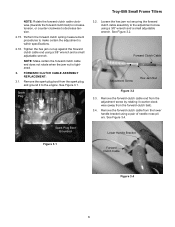
...of the lower cable mounting bracket. 3.10. Remove the lower cable tie securing the forward clutch cable to the lower handlebar using a 3/8" socket. Remove the hex flange screw and large flat washer securing the belt cover to the lower cable mounting bracket...reverse order above. 3.13. See Figure 3.5. See Figure 3.8. Hex Flange Screw Figure 3.8 3.9. Remove the lower portion of the work area. Troy-Bilt Small Frame Tillers 3.5. Forward Idler Lever Forward Clutch Cable Clutch Cable Z Fitting Hex Jam Nut Figure 3.5 3.6. Slide the forward clutch cable out of the forward...
...of the lower cable mounting bracket. 3.10. Remove the lower cable tie securing the forward clutch cable to the lower handlebar using a 3/8" socket. Remove the hex flange screw and large flat washer securing the belt cover to the lower cable mounting bracket...reverse order above. 3.13. See Figure 3.5. See Figure 3.8. Hex Flange Screw Figure 3.8 3.9. Remove the lower portion of the work area. Troy-Bilt Small Frame Tillers 3.5. Forward Idler Lever Forward Clutch Cable Clutch Cable Z Fitting Hex Jam Nut Figure 3.5 3.6. Slide the forward clutch cable out of the forward...
Service Manual
Page 9
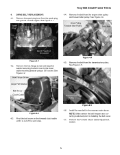
... from the engine drive pulley and forward idler pulley. NOTE: Make certain the belt keepers are correctly positioned prior to the engine. Spark Plug Troy-Bilt Small Frame Tillers 4.4. Pivot the belt cover on the forward clutch cable until it to installing the belt cover. 4.7. See Figure 4.4. See Figure 4.5. See Figure 4.2. 4. Hex Flange... the transmission pulley. DRIVE BELT REPLACEMENT: 4.1. Remove the hex flange screw and large flat washer securing the belt cover to the lower cable mounting bracket using a 3/8" socket.
... from the engine drive pulley and forward idler pulley. NOTE: Make certain the belt keepers are correctly positioned prior to the engine. Spark Plug Troy-Bilt Small Frame Tillers 4.4. Pivot the belt cover on the forward clutch cable until it to installing the belt cover. 4.7. See Figure 4.4. See Figure 4.5. See Figure 4.2. 4. Hex Flange... the transmission pulley. DRIVE BELT REPLACEMENT: 4.1. Remove the hex flange screw and large flat washer securing the belt cover to the lower cable mounting bracket using a 3/8" socket.
Service Manual
Page 10
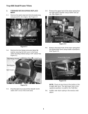
...holes at the bottom of the return spring from the forward idler lever using needle nose pliers. See Figure 5.1. See Figure 5.2. The right lower hole (in the reverse order above. 6 Troy-Bilt Small Frame Tillers 5. Spark Plug 5.4. FORWARD RETURN SPRING REPLACEMENT: 5.1. Remove the upper... hook of the return spring from the spark plug, and ground it is used for the Tuffy tiller. 5.6. Install a new return spring in the operators...
...holes at the bottom of the return spring from the forward idler lever using needle nose pliers. See Figure 5.1. See Figure 5.2. The right lower hole (in the reverse order above. 6 Troy-Bilt Small Frame Tillers 5. Spark Plug 5.4. FORWARD RETURN SPRING REPLACEMENT: 5.1. Remove the upper... hook of the return spring from the spark plug, and ground it is used for the Tuffy tiller. 5.6. Install a new return spring in the operators...
Service Manual
Page 11
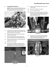
... clutch cable from the belt cover. 6.5. Remove both self tapping hex flange screws securing the tine hood to the right and left hood brackets using a 1/2" socket. Troy-Bilt Small Frame Tillers 6. Secure the handlebar from the forward idler lever. 6.4. performing this section. Pivot the trailing shield up. Remove both hex flange screws securing the...
... clutch cable from the belt cover. 6.5. Remove both self tapping hex flange screws securing the tine hood to the right and left hood brackets using a 1/2" socket. Troy-Bilt Small Frame Tillers 6. Secure the handlebar from the forward idler lever. 6.4. performing this section. Pivot the trailing shield up. Remove both hex flange screws securing the...
Service Manual
Page 12
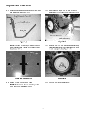
Troy-Bilt Small Frame Tillers 6.12. Raise the front of the tiller up until the wheel assemblies are off Ground Raise the Unit Up Figure 6.14 6.15. Lower the unit back onto the tines. Hair Pin Clevis ... resting on the tines and not on the trailing shield. Remove both hair pins and clevis pins securing the wheel assemblies onto the wheel shaft using needle nose pliers. See Figure 6.15. Cut A Way Wheels off the ground. Remove the depth regulator assembly and drag bar assembly. See Figure 6.14...
Troy-Bilt Small Frame Tillers 6.12. Raise the front of the tiller up until the wheel assemblies are off Ground Raise the Unit Up Figure 6.14 6.15. Lower the unit back onto the tines. Hair Pin Clevis ... resting on the tines and not on the trailing shield. Remove both hair pins and clevis pins securing the wheel assemblies onto the wheel shaft using needle nose pliers. See Figure 6.15. Cut A Way Wheels off the ground. Remove the depth regulator assembly and drag bar assembly. See Figure 6.14...


