
User Guide
Page 12
... JAPAN APPROVALS INSTITUTE FOR TELECOMMUNICATIONS EQUIPMENT Approval Number: D01-1128JP TELECOM ENGINEERING CENTER Approval Number: 03NY.A0018, 03GZDA0017 The following restrictions apply: ❖ Do not disassemble or modify the device. ❖ Do not install the embedded wireless module into other device. ❖ 5.17 GHz to the device class of radio equipment...
... JAPAN APPROVALS INSTITUTE FOR TELECOMMUNICATIONS EQUIPMENT Approval Number: D01-1128JP TELECOM ENGINEERING CENTER Approval Number: 03NY.A0018, 03GZDA0017 The following restrictions apply: ❖ Do not disassemble or modify the device. ❖ Do not install the embedded wireless module into other device. ❖ 5.17 GHz to the device class of radio equipment...

User Guide
Page 21
Always contact an authorized Toshiba service provider, if any other optical drive. Never attempt to disassemble, adjust or repair a HD DVD, CD/DVD drive, CD-RW drive, Multi-drive or any repair or adjustment is classified as a CLASS 1 LASER ... manufacturing information may vary.) Location of the radio equipment: EYXF2CS TELECOM ENGINEERING CENTER Approval Number: 01NYDA1305 The following restrictions apply: ❖ Do not disassemble or modify the device. ❖ Do not install the embedded wireless module into other safety hazards, resulting in the Radio Law of the Required ...
Always contact an authorized Toshiba service provider, if any other optical drive. Never attempt to disassemble, adjust or repair a HD DVD, CD/DVD drive, CD-RW drive, Multi-drive or any repair or adjustment is classified as a CLASS 1 LASER ... manufacturing information may vary.) Location of the radio equipment: EYXF2CS TELECOM ENGINEERING CENTER Approval Number: 01NYDA1305 The following restrictions apply: ❖ Do not disassemble or modify the device. ❖ Do not install the embedded wireless module into other safety hazards, resulting in the Radio Law of the Required ...

User Guide
Page 108
... battery pack produces an odor, overheats or changes color or shape while it immediately. Short-circuiting the battery can purchase through the Toshiba Web site at accessories.toshiba.com. ❖ A reverse polarity condition should hear a click when it . ❖ Avoid touching the metal terminals of the... it to fire. 108 Mobile Computing Taking care of your battery Taking care of your battery The following sections offer tips on how to disassemble a battery pack. ❖ Do not overcharge or reverse charge a battery. Carefully remove the battery pack from the power socket. The...
... battery pack produces an odor, overheats or changes color or shape while it immediately. Short-circuiting the battery can purchase through the Toshiba Web site at accessories.toshiba.com. ❖ A reverse polarity condition should hear a click when it . ❖ Avoid touching the metal terminals of the... it to fire. 108 Mobile Computing Taking care of your battery Taking care of your battery The following sections offer tips on how to disassemble a battery pack. ❖ Do not overcharge or reverse charge a battery. Carefully remove the battery pack from the power socket. The...

Maintenance Manual
Page 9
... ...3.54 3.11 Error Codes and description 3.56 3.12 Quick Test Item List i Chapter 4 Replacement Procedures 4.1 General ...4-1 Safety Precautions 4-2 Before You Begin 4-4 Disassembly Procedures 4-5 Assembly Procedures 4-5 Tools and Equipment 4-6 Screw Tightening Torque 4-6 Colors of Screw Shanks 4-7 Symbols of Screws on the Computer Body 4-7 Symbol examples 4-7 ...PC Card 4-10 Installing the Optional PC Card 4-11 Removing the Momery Card 4-12 Installing the Momery Card 4-13 Satellite A210/A215/Satellite Pro A210/EQUIUM A210/SATEGO A210 Maintenance Manual ix
... ...3.54 3.11 Error Codes and description 3.56 3.12 Quick Test Item List i Chapter 4 Replacement Procedures 4.1 General ...4-1 Safety Precautions 4-2 Before You Begin 4-4 Disassembly Procedures 4-5 Assembly Procedures 4-5 Tools and Equipment 4-6 Screw Tightening Torque 4-6 Colors of Screw Shanks 4-7 Symbols of Screws on the Computer Body 4-7 Symbol examples 4-7 ...PC Card 4-10 Installing the Optional PC Card 4-11 Removing the Momery Card 4-12 Installing the Momery Card 4-13 Satellite A210/A215/Satellite Pro A210/EQUIUM A210/SATEGO A210 Maintenance Manual ix

Maintenance Manual
Page 10
... ...4-16 Removing the HDD 4-16 Installing the HDD 4-18 4.3 ODD Bay Module 4-19 Removing the ODD Bay Module 4-19 Installing the ODD Bay Module 4-20 Disassembling the ODD Bay Module 4-21 Assembling the ODD Bay Module 4-21 4.4 Speaker Cover and Keyboard 4-22 Removing the Speaker Cover and Keyboard 4-22 Installing the... Top Cover 4-34 4.10 Speakers ...4-35 Removing the Speakers 4-35 Installing the Speakers 4-35 4.11 USB and CRT cable, Fingerprint Board and Bluetooth Card 4-36 x Satellite A210/A215/Satellite Pro A210/EQUIUM A210/SATEGO A210 Maintenance Manual
... ...4-16 Removing the HDD 4-16 Installing the HDD 4-18 4.3 ODD Bay Module 4-19 Removing the ODD Bay Module 4-19 Installing the ODD Bay Module 4-20 Disassembling the ODD Bay Module 4-21 Assembling the ODD Bay Module 4-21 4.4 Speaker Cover and Keyboard 4-22 Removing the Speaker Cover and Keyboard 4-22 Installing the... Top Cover 4-34 4.10 Speakers ...4-35 Removing the Speakers 4-35 Installing the Speakers 4-35 4.11 USB and CRT cable, Fingerprint Board and Bluetooth Card 4-36 x Satellite A210/A215/Satellite Pro A210/EQUIUM A210/SATEGO A210 Maintenance Manual

Maintenance Manual
Page 50
...Make sure the AC adaptor and AC power cord have been connected correctly, perform Check 2. Check 2 Replace the system board with a new one . 2-8 Satellite A210/A215/Satellite Pro A210/EQUIUM A210/SATEGO A210 Maintenance Manual 2 Troubleshooting 2.3 Power Supply Procedure 2 Connection Check Power is supplied to the system board as illustrated below: AC adaptor System board AC power... properly, perform Check 3. Check 3 Replace the CPU with a new one . Check 3 Make sure the battery pack has been correctly installed in the computer. Disassemble the computer according to Procedure 3.
...Make sure the AC adaptor and AC power cord have been connected correctly, perform Check 2. Check 2 Replace the system board with a new one . 2-8 Satellite A210/A215/Satellite Pro A210/EQUIUM A210/SATEGO A210 Maintenance Manual 2 Troubleshooting 2.3 Power Supply Procedure 2 Connection Check Power is supplied to the system board as illustrated below: AC adaptor System board AC power... properly, perform Check 3. Check 3 Replace the CPU with a new one . Check 3 Make sure the battery pack has been correctly installed in the computer. Disassemble the computer according to Procedure 3.

Maintenance Manual
Page 52
... Check The system board, memory, or CPU may be defective. Mouse test 7. Disassemble the computer following test programs using the procedures described in Chapter 4 and replace the system board, memory module or CPU with a new one. 2-10 Satellite A210/A215/Satellite Pro A210/EQUIUM A210/SATEGO A210 Maintenance Manual ODD test 9. Hard Disk test 6. System test 2. Sound test...
... Check The system board, memory, or CPU may be defective. Mouse test 7. Disassemble the computer following test programs using the procedures described in Chapter 4 and replace the system board, memory module or CPU with a new one. 2-10 Satellite A210/A215/Satellite Pro A210/EQUIUM A210/SATEGO A210 Maintenance Manual ODD test 9. Hard Disk test 6. System test 2. Sound test...

Maintenance Manual
Page 56
... firmly and return to the HDD, system board and CPU. Replace it with a new one following the disassembling instructions in Chapter 4. 2-14 Satellite A210/A215/Satellite Pro A210/EQUIUM A210/SATEGO A210 Maintenance Manual Replace it with a new one following the disassembling instructions in Chapter 4. HDD System board CPU If any connector is still an error, perform Check 2. Check...
... firmly and return to the HDD, system board and CPU. Replace it with a new one following the disassembling instructions in Chapter 4. 2-14 Satellite A210/A215/Satellite Pro A210/EQUIUM A210/SATEGO A210 Maintenance Manual Replace it with a new one following the disassembling instructions in Chapter 4. HDD System board CPU If any connector is still an error, perform Check 2. Check...

Maintenance Manual
Page 57
...Test Program Check Procedure 2 Connector Check and Replacement Check Procedure 1 Test Program Check Execute the Keyboard test available as instructed. Disassemble the computer following the steps described in Chapter 4. Replace it with a new one following checks: Check 1 Make sure the...and perform the following the instructions in Chapter 4. If the keyboard is still an error, perform Check 2. Satellite A210/A215/Satellite Pro A210/EQUIUM A210/SATEGO A210 Maintenance Manual 2-15 The memory may be faulty. Procedure 2 Connector Check and Replacement Check The keyboard or ...
...Test Program Check Procedure 2 Connector Check and Replacement Check Procedure 1 Test Program Check Execute the Keyboard test available as instructed. Disassemble the computer following the steps described in Chapter 4. Replace it with a new one following checks: Check 1 Make sure the...and perform the following the instructions in Chapter 4. If the keyboard is still an error, perform Check 2. Satellite A210/A215/Satellite Pro A210/EQUIUM A210/SATEGO A210 Maintenance Manual 2-15 The memory may be faulty. Procedure 2 Connector Check and Replacement Check The keyboard or ...

Maintenance Manual
Page 58
.... The computer automatically detects the external monitor even if resume mode is still an error, perform Check 3. 2-16 Satellite A210/A215/Satellite Pro A210/EQUIUM A210/SATEGO A210 Maintenance Manual If the external monitor appears to have been firmly connected to Procedure 3. If an error is detected in...board may be faulty. If the external monitor works correctly, the internal LCD, LCD/FL cable, or FL may be defective. Disassemble the computer following the steps described in Chapter 4, then perform the following cables have the same problem as instructed. Procedure 1 External...
.... The computer automatically detects the external monitor even if resume mode is still an error, perform Check 3. 2-16 Satellite A210/A215/Satellite Pro A210/EQUIUM A210/SATEGO A210 Maintenance Manual If the external monitor appears to have been firmly connected to Procedure 3. If an error is detected in...board may be faulty. If the external monitor works correctly, the internal LCD, LCD/FL cable, or FL may be defective. Disassemble the computer following the steps described in Chapter 4, then perform the following cables have the same problem as instructed. Procedure 1 External...
Maintenance Manual
Page 60
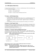
Then insert a test ODD (Toshiba-EMI DVD-ROM TEST DISK TSD-1) into the eject hole. Disassemble the computer following the steps described in the computer's CD, turn on how to Procedure 2. Insert the diagnostics CD in Chapter 4 ...connector with a lens cleaner. Procedure 3 Connector Check and Replacement Check The ODD drive is still not functioning properly, perform Check 3. 2-18 Satellite A210/A215/Satellite Pro A210/EQUIUM A210/SATEGO A210 Maintenance Manual If the ODD drive is connected to the ODD drive and the system board. The object must be faulty. Clean the laser...
Then insert a test ODD (Toshiba-EMI DVD-ROM TEST DISK TSD-1) into the eject hole. Disassemble the computer following the steps described in the computer's CD, turn on how to Procedure 2. Insert the diagnostics CD in Chapter 4 ...connector with a lens cleaner. Procedure 3 Connector Check and Replacement Check The ODD drive is still not functioning properly, perform Check 3. 2-18 Satellite A210/A215/Satellite Pro A210/EQUIUM A210/SATEGO A210 Maintenance Manual If the ODD drive is connected to the ODD drive and the system board. The object must be faulty. Clean the laser...

Maintenance Manual
Page 62
... with a new one . 2-20 Satellite A210/A215/Satellite Pro A210/EQUIUM A210/SATEGO A210 Maintenance Manual If the LAN is defective or malfunctioning, follow the troubleshooting procedures below as part of the maintenance test program. The CPU may be defective. Disassemble the computer following the steps described in...2 Procedure 2 Connector Check and Replacement Check The LAN connector (RJ45) is detected by the check, go to perform the check. Disassemble the computer following checks: Check 1 Check 2 Check 3 The system board may be faulty. Replace the memory module with a new...
... with a new one . 2-20 Satellite A210/A215/Satellite Pro A210/EQUIUM A210/SATEGO A210 Maintenance Manual If the LAN is defective or malfunctioning, follow the troubleshooting procedures below as part of the maintenance test program. The CPU may be defective. Disassemble the computer following the steps described in...2 Procedure 2 Connector Check and Replacement Check The LAN connector (RJ45) is detected by the check, go to perform the check. Disassemble the computer following checks: Check 1 Check 2 Check 3 The system board may be faulty. Replace the memory module with a new...

Maintenance Manual
Page 63
... 2 Connector Check The Memory Card connector is still not functioning properly, perform Check 2. Disassemble the computer following the steps described in Chapter 4 and perform the following the steps described in Chapter 4. The memory may be faulty. Satellite A210/A215/Satellite Pro A210/EQUIUM A210/SATEGO A210 Maintenance Manual 2-21 If the problem persists, perform Check 3. This program checks...
... 2 Connector Check The Memory Card connector is still not functioning properly, perform Check 2. Disassemble the computer following the steps described in Chapter 4 and perform the following the steps described in Chapter 4. The memory may be faulty. Satellite A210/A215/Satellite Pro A210/EQUIUM A210/SATEGO A210 Maintenance Manual 2-21 If the problem persists, perform Check 3. This program checks...

Maintenance Manual
Page 64
... to Procedure 2 Procedure 2 Connector Check The Finger Print connector is still not functioning properly, perform Check 2. Then go through procedure 1 again. 2-22 Satellite A210/A215/Satellite Pro A210/EQUIUM A210/SATEGO A210 Maintenance Manual Disassemble the computer following the steps described in Chapter 4 and perform the following the steps described in Chapter 4. 2 Troubleshooting 2.11 Finger Print (Optional) 2.11...
... to Procedure 2 Procedure 2 Connector Check The Finger Print connector is still not functioning properly, perform Check 2. Then go through procedure 1 again. 2-22 Satellite A210/A215/Satellite Pro A210/EQUIUM A210/SATEGO A210 Maintenance Manual Disassemble the computer following the steps described in Chapter 4 and perform the following the steps described in Chapter 4. 2 Troubleshooting 2.11 Finger Print (Optional) 2.11...

Maintenance Manual
Page 65
...5. The CPU may be disconnected or faulty. Procedure 2 Connector Check and Replacement Check The Audio or system board may be defective. Satellite A210/A215/Satellite Pro A210/EQUIUM A210/SATEGO A210 Maintenance Manual 2-23 If an error is defective or malfunctioning, follow the troubleshooting procedures below as part of the maintenance test program.... Audio Test 2 Troubleshooting 2.12 Audio Test To check if the computer's Speaker is detected in the test, go to Procedure 2. Disassemble the computer following the steps described in Chapter 4 and replace the CPU with a new one .
...5. The CPU may be disconnected or faulty. Procedure 2 Connector Check and Replacement Check The Audio or system board may be defective. Satellite A210/A215/Satellite Pro A210/EQUIUM A210/SATEGO A210 Maintenance Manual 2-23 If an error is defective or malfunctioning, follow the troubleshooting procedures below as part of the maintenance test program.... Audio Test 2 Troubleshooting 2.12 Audio Test To check if the computer's Speaker is detected in the test, go to Procedure 2. Disassemble the computer following the steps described in Chapter 4 and replace the CPU with a new one .

Maintenance Manual
Page 66
... IEEE 1394 connector is mounted on the computer and run the test. Replace the memory module with a new one . 2-24 Satellite A210/A215/Satellite Pro A210/EQUIUM A210/SATEGO A210 Maintenance Manual Disassemble the computer following the steps described in Chapter 4. The CPU may be faulty. If the problem persists, perform Check 3. 2 Troubleshooting... malfunctions, the system board or CPU might be defective. If any error is still not functioning properly, perform Check 2. Disassemble the computer following checks: Check 1 Check 2 Check 3 The system board may be faulty.
... IEEE 1394 connector is mounted on the computer and run the test. Replace the memory module with a new one . 2-24 Satellite A210/A215/Satellite Pro A210/EQUIUM A210/SATEGO A210 Maintenance Manual Disassemble the computer following the steps described in Chapter 4. The CPU may be faulty. If the problem persists, perform Check 3. 2 Troubleshooting... malfunctions, the system board or CPU might be defective. If any error is still not functioning properly, perform Check 2. Disassemble the computer following checks: Check 1 Check 2 Check 3 The system board may be faulty.

Maintenance Manual
Page 67
...information on the computer and run the test. If any part of the fan and that the fan is free of foreign matter. Disassemble the computer following the steps described in Chapter 4 and perform the following the steps in the fan, remove it with a new...board and return to the system board. If a foreign matter is found in Chapter 4. If there is connected to Procedure 1. Satellite A210/A215/Satellite Pro A210/EQUIUM A210/SATEGO A210 Maintenance Manual 2-25 If the cooling module malfunctions, there may be faulty. Procedure 1 Test Program Check Procedure 2 Connector Check ...
...information on the computer and run the test. If any part of the fan and that the fan is free of foreign matter. Disassemble the computer following the steps described in Chapter 4 and perform the following the steps in the fan, remove it with a new...board and return to the system board. If a foreign matter is found in Chapter 4. If there is connected to Procedure 1. Satellite A210/A215/Satellite Pro A210/EQUIUM A210/SATEGO A210 Maintenance Manual 2-25 If the cooling module malfunctions, there may be faulty. Procedure 1 Test Program Check Procedure 2 Connector Check ...

Maintenance Manual
Page 68
2 Troubleshooting 2.14 Cooling Module Check 3 Check 4 The memory may be defective. If the problem persists, perform Check 4. Disassemble the computer following the steps described in Chapter 4 and replace the CPU with a new one . 2-26 Satellite A210/A215/Satellite Pro A210/EQUIUM A210/SATEGO A210 Maintenance Manual Replace the memory module with a new one following the steps described in Chapter 4. The CPU may be faulty.
2 Troubleshooting 2.14 Cooling Module Check 3 Check 4 The memory may be defective. If the problem persists, perform Check 4. Disassemble the computer following the steps described in Chapter 4 and replace the CPU with a new one . 2-26 Satellite A210/A215/Satellite Pro A210/EQUIUM A210/SATEGO A210 Maintenance Manual Replace the memory module with a new one following the steps described in Chapter 4. The CPU may be faulty.

Maintenance Manual
Page 136
4 Replacement Procedures Chapter 4 Contents 4.1 General...4-1 Safety Precautions 4-2 Before You Begin 4-4 Disassembly Procedures 4-5 Assembly Procedures 4-5 Tools and Equipment 4-6 Screw Tightening Torque 4-6 Colors of Screw Shanks 4-7 Symbols of Screws on the...Module ...4-19 Removing the ODD Bay Module 4-19 Installing the ODD Bay Module 4-20 Disassembling the ODD Bay Module 4-21 Assembling the ODD Bay Module 4-21 4.4 Speaker Cover and Keyboard 4-22 Removing the Speaker Cover and Keyboard 4-22 Satellite A210/A215/Satellite Pro A210/EQUIUM A210/SATEGO A210 Maintenance Manual 4-iii
4 Replacement Procedures Chapter 4 Contents 4.1 General...4-1 Safety Precautions 4-2 Before You Begin 4-4 Disassembly Procedures 4-5 Assembly Procedures 4-5 Tools and Equipment 4-6 Screw Tightening Torque 4-6 Colors of Screw Shanks 4-7 Symbols of Screws on the...Module ...4-19 Removing the ODD Bay Module 4-19 Installing the ODD Bay Module 4-20 Disassembling the ODD Bay Module 4-21 Assembling the ODD Bay Module 4-21 4.4 Speaker Cover and Keyboard 4-22 Removing the Speaker Cover and Keyboard 4-22 Satellite A210/A215/Satellite Pro A210/EQUIUM A210/SATEGO A210 Maintenance Manual 4-iii

Maintenance Manual
Page 141
... Module CPU 4. 16 Display Mask 4. 17 FL Inverter Board 4. 18 CCD Board and MIC 4. 19 LCD Modules How to disassemble the computer and replace Field Replaceable Units (FRUs). After you to remove all of which they should normally be removed in which ... Module CPU 4. 16 Display Mask 4. 17 FL Inverter Board 4. 18 CCD Board and MIC 4. 19 LCD Modules System Board LCD Module Satellite A210/A215/Satellite Pro A210/EQUIUM A210/SATEGO A210 Maintenance Manual 4-1 4.1 General 4 Replacement Procedures 4 1 4.1 General This chapter explains how to use the chart (two examples): • ...
... Module CPU 4. 16 Display Mask 4. 17 FL Inverter Board 4. 18 CCD Board and MIC 4. 19 LCD Modules How to disassemble the computer and replace Field Replaceable Units (FRUs). After you to remove all of which they should normally be removed in which ... Module CPU 4. 16 Display Mask 4. 17 FL Inverter Board 4. 18 CCD Board and MIC 4. 19 LCD Modules System Board LCD Module Satellite A210/A215/Satellite Pro A210/EQUIUM A210/SATEGO A210 Maintenance Manual 4-1 4.1 General 4 Replacement Procedures 4 1 4.1 General This chapter explains how to use the chart (two examples): • ...


