User Manual
Page 3
...antenna. ❖ Increase the separation between the external devices and the computer's parallel port, monitor port, USB port, PS/2 port®, i.LINK® port, HDMI out port and microphone jack (Port availability depends on a circuit different from that interference will not occur in accordance with... noncompliant peripherals or peripherals not recommended by Toshiba could lead to injury to ...
...antenna. ❖ Increase the separation between the external devices and the computer's parallel port, monitor port, USB port, PS/2 port®, i.LINK® port, HDMI out port and microphone jack (Port availability depends on a circuit different from that interference will not occur in accordance with... noncompliant peripherals or peripherals not recommended by Toshiba could lead to injury to ...
User Manual
Page 31
... Inserting memory media 137 Removing memory media 137 Using the i.LINK® port 138 Chapter 5: Toshiba Utilities 139 TOSHIBA Assist 140 Connect 141 Secure 142 Protect & Fix 143 Optimize 144 Toshiba Application Installer 145 Setting passwords 146 Using an instant password 146 Using a ... 147 Using a user password 148 Deleting a user password 149 TOSHIBA PC Diagnostic Tool Utility 150 TOSHIBA SD™ Memory Card Format Utility .........151 Mouse Utility 152 Toshiba Hardware Setup 153 TOSHIBA Zooming Utility 155 TOSHIBA Button Support 156 CD/DVD Drive Acoustic Silencer 157...
... Inserting memory media 137 Removing memory media 137 Using the i.LINK® port 138 Chapter 5: Toshiba Utilities 139 TOSHIBA Assist 140 Connect 141 Secure 142 Protect & Fix 143 Optimize 144 Toshiba Application Installer 145 Setting passwords 146 Using an instant password 146 Using a ... 147 Using a user password 148 Deleting a user password 149 TOSHIBA PC Diagnostic Tool Utility 150 TOSHIBA SD™ Memory Card Format Utility .........151 Mouse Utility 152 Toshiba Hardware Setup 153 TOSHIBA Zooming Utility 155 TOSHIBA Button Support 156 CD/DVD Drive Acoustic Silencer 157...
User Manual
Page 68
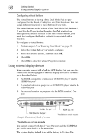
... of the Dual Mode Pad (buttons 4, 5, and 6 in "Enabling Dual Mode" on certain models You cannot connect both the S-video Out port and the HDMI Out port to the same device at the same time. To configure a virtual button: 1 Perform steps 1-5 in the Properties for the Email, ConfigFree, ... can assign different functions to these buttons, you must first configure that button so that it is set at the top of system HDMI Out port* *Available on certain models *Available on page 67. 2 Select the virtual button you wish. 68 Getting Started Using external display devices Configuring...
... of the Dual Mode Pad (buttons 4, 5, and 6 in "Enabling Dual Mode" on certain models You cannot connect both the S-video Out port and the HDMI Out port to the same device at the same time. To configure a virtual button: 1 Perform steps 1-5 in the Properties for the Email, ConfigFree, ... can assign different functions to these buttons, you must first configure that button so that it is set at the top of system HDMI Out port* *Available on certain models *Available on page 67. 2 Select the virtual button you wish. 68 Getting Started Using external display devices Configuring...
User Manual
Page 69
...Toshiba recommends using a cable no longer than 20 feet (approximately 6 meters). If you are applicable in a dull or fuzzy picture, poor color, ghosting, video noise, or loss of cable entrance, or attachment, as practicable and the connection complies with your area. Selecting video cables To connect a device to the S-video port... use a properly shielded cable. If you are connecting a standard television or other video display device to the computer's HDMI Out port, first refer to "Selecting video cables" on page 69 for guidelines on choosing a video cable, then refer to "Connecting a...
...Toshiba recommends using a cable no longer than 20 feet (approximately 6 meters). If you are applicable in a dull or fuzzy picture, poor color, ghosting, video noise, or loss of cable entrance, or attachment, as practicable and the connection complies with your area. Selecting video cables To connect a device to the S-video port... use a properly shielded cable. If you are connecting a standard television or other video display device to the computer's HDMI Out port, first refer to "Selecting video cables" on page 69 for guidelines on choosing a video cable, then refer to "Connecting a...
User Manual
Page 70
... you may prefer to use the computer's built-in display you connect to a sound system that supports input from your computer) to the HDMI Out port on the side of the computer's built-in two ways: ❖ Using the headphone jack on one end and a plug compatible with the television for...
... you may prefer to use the computer's built-in display you connect to a sound system that supports input from your computer) to the HDMI Out port on the side of the computer's built-in two ways: ❖ Using the headphone jack on one end and a plug compatible with the television for...
User Manual
Page 71
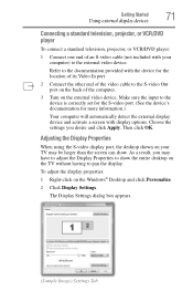
...Tab Make sure the input to the device is correctly set for the S-video port. (See the device's documentation for the location of its Video In port. 2 Connect the other end of the video cable to the S-video Out port on your computer) to show . Adjusting the Display Properties When using the S-...video display port, the desktop shown on the back of an S-video cable (not included ...
...Tab Make sure the input to the device is correctly set for the S-video port. (See the device's documentation for the location of its Video In port. 2 Connect the other end of the video cable to the S-video Out port on your computer) to show . Adjusting the Display Properties When using the S-...video display port, the desktop shown on the back of an S-video cable (not included ...
User Manual
Page 72
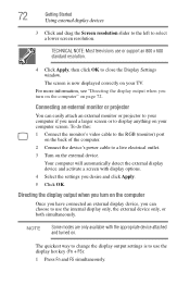
To do this: 1 Connect the monitor's video cable to the RGB (monitor) port on the back of the computer. 2 Connect the device's power cable to display anything on your computer screen. Your computer will automatically detect the external ...
To do this: 1 Connect the monitor's video cable to the RGB (monitor) port on the back of the computer. 2 Connect the device's power cable to display anything on your computer screen. Your computer will automatically detect the external ...
User Manual
Page 74
The external display device must set the resolution of the internal display panel to your computer through the USB ports. Using a mouse You may require you to install the printer software before physically connecting the printer to match the resolution of 800 x 600 or ... can connect a USB-compatible printer to use a USB-compatible mouse. You can use a mouse instead of the computer's built-in TouchPad. The computer's USB ports support any USB-compatible keyboard. Using an external keyboard If you prefer to use one to adjust the video settings. TECHNICAL NOTE: To use a full...
The external display device must set the resolution of the internal display panel to your computer through the USB ports. Using a mouse You may require you to install the printer software before physically connecting the printer to match the resolution of 800 x 600 or ... can connect a USB-compatible printer to use a USB-compatible mouse. You can use a mouse instead of the computer's built-in TouchPad. The computer's USB ports support any USB-compatible keyboard. Using an external keyboard If you prefer to use one to adjust the video settings. TECHNICAL NOTE: To use a full...
User Manual
Page 75
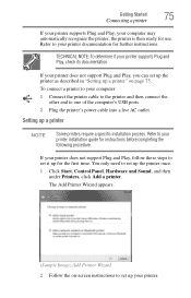
... supports Plug and Play, your computer: 1 Connect the printer cable to the printer and then connect the other end to one of the computer's USB ports. 2 Plug the printer's power cable into a live AC outlet.
... supports Plug and Play, your computer: 1 Connect the printer cable to the printer and then connect the other end to one of the computer's USB ports. 2 Plug the printer's power cable into a live AC outlet.
User Manual
Page 76
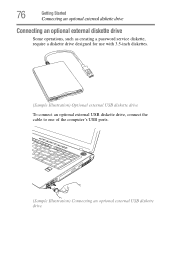
76 Getting Started Connecting an optional external diskette drive Connecting an optional external diskette drive Some operations, such as creating a password service diskette, require a diskette drive designed for use with 3.5-inch diskettes. (Sample Illustration) Optional external USB diskette drive To connect an optional external USB diskette drive, connect the cable to one of the computer's USB ports. (Sample Illustration) Connecting an optional external USB diskette drive
76 Getting Started Connecting an optional external diskette drive Connecting an optional external diskette drive Some operations, such as creating a password service diskette, require a diskette drive designed for use with 3.5-inch diskettes. (Sample Illustration) Optional external USB diskette drive To connect an optional external USB diskette drive, connect the cable to one of the computer's USB ports. (Sample Illustration) Connecting an optional external USB diskette drive
User Manual
Page 106
... depending on product model, configuration, applications, power management settings and features utilized, as well as the natural performance variations produced by Toshiba at the time of individual components. To ensure that you play DVDs while running the computer on AC power. Please see "Maintaining... the battery may fail to be inaccurate. Published battery life numbers are achieved on AC power, either through an AC adaptor or a port replicator (if applicable to your system configuration settings and the current time and date information. After a period of time, the battery will...
... depending on product model, configuration, applications, power management settings and features utilized, as well as the natural performance variations produced by Toshiba at the time of individual components. To ensure that you play DVDs while running the computer on AC power. Please see "Maintaining... the battery may fail to be inaccurate. Published battery life numbers are achieved on AC power, either through an AC adaptor or a port replicator (if applicable to your system configuration settings and the current time and date information. After a period of time, the battery will...
User Manual
Page 126
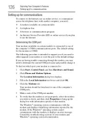
...Internet, use an online service, or communicate across the telephone lines with another computer, you need to determine the current COM port name and possibly change it displays an error message. The Location Information dialog box displays. 3 Fill in the Local Information text... boxes and click OK. 4 Click the Modems tab. Consult the troubleshooting sections of the computer's COM (communications) ports. If the Windows® operating system cannot communicate with the modem and displays identifying information reported by the modem. The Windows® ...
...Internet, use an online service, or communicate across the telephone lines with another computer, you need to determine the current COM port name and possibly change it displays an error message. The Location Information dialog box displays. 3 Fill in the Local Information text... boxes and click OK. 4 Click the Modems tab. Consult the troubleshooting sections of the computer's COM (communications) ports. If the Windows® operating system cannot communicate with the modem and displays identifying information reported by the modem. The Windows® ...

User Manual
Page 127
...specific information about connecting to close the properties dialog box for that can communicate using the modem, you need to connect it to the modem port Exploring Your Computer's Features Setting up for communications 127 7 Click OK to close the Phone and Modem Options dialog box. 9 Close the Control...telephone cable to a telephone line. Connecting a modem to a telephone line (Available on the right side of a telephone cable (purchased separately) into the modem port on certain models) Your computer may come with your computer's modem, visit Toshiba's Web site at accessories...
...specific information about connecting to close the properties dialog box for that can communicate using the modem, you need to connect it to the modem port Exploring Your Computer's Features Setting up for communications 127 7 Click OK to close the Phone and Modem Options dialog box. 9 Close the Control...telephone cable to a telephone line. Connecting a modem to a telephone line (Available on the right side of a telephone cable (purchased separately) into the modem port on certain models) Your computer may come with your computer's modem, visit Toshiba's Web site at accessories...

User Manual
Page 128
...-Fi® access. Ask your computer. Never connect the built-in modem to a digital private branch exchange (PBX). Connecting your computer to increase its communication ports. For specific information about connecting to the network, consult your computer to a network to a network You can connect your network administrator. 128 Exploring Your Computer...
...-Fi® access. Ask your computer. Never connect the built-in modem to a digital private branch exchange (PBX). Connecting your computer to increase its communication ports. For specific information about connecting to the network, consult your computer to a network to a network You can connect your network administrator. 128 Exploring Your Computer...

User Manual
Page 129
... Adapter. 4 Double-click the appropriate network adapter. 5 Select the Driver tab. 6 Click Disable. 7 Click Yes. 8 Click OK. To disable the LAN port: 1 Click Start, Control Panel, System and Maintenance, and then System. 2 Click Device Manager under Tasks on the left side of your Internet connection. 4 Click... Connect and let the program dial the number. To enable the Ethernet LAN port, repeat steps 1-4. Exploring Your Computer's Features Setting up for communications 129 Setting up the connection To set up a dial-up an office...
... Adapter. 4 Double-click the appropriate network adapter. 5 Select the Driver tab. 6 Click Disable. 7 Click Yes. 8 Click OK. To disable the LAN port: 1 Click Start, Control Panel, System and Maintenance, and then System. 2 Click Device Manager under Tasks on the left side of your Internet connection. 4 Click... Connect and let the program dial the number. To enable the Ethernet LAN port, repeat steps 1-4. Exploring Your Computer's Features Setting up for communications 129 Setting up the connection To set up a dial-up an office...
User Manual
Page 138
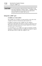
...might still be in real-time, such as video devices. Using the i.LINK® port (Available on certain models) The i.LINK® port (available on certain models) on ). As with USB ports, the i.LINK® port supports both Plug-and-Play (automatic configuration) and hot swapping (the ability to high speed...that transfer high levels of data in progress and your data could be destroyed. 138 Exploring Your Computer's Features Using the i.LINK® port Do not remove memory media while data is on the side of the computer provides an extremely fast data transfer rate. Even when the...
...might still be in real-time, such as video devices. Using the i.LINK® port (Available on certain models) The i.LINK® port (available on certain models) on ). As with USB ports, the i.LINK® port supports both Plug-and-Play (automatic configuration) and hot swapping (the ability to high speed...that transfer high levels of data in progress and your data could be destroyed. 138 Exploring Your Computer's Features Using the i.LINK® port Do not remove memory media while data is on the side of the computer provides an extremely fast data transfer rate. Even when the...
User Manual
Page 191
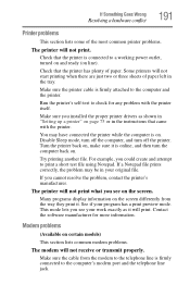
... telephone line is online, and then turn off the computer, and turn the computer back on. Run the printer's self-test to the computer's modem port and the telephone line jack. The printer will not start printing when there are just two or three sheets of paper left in your program...
... telephone line is online, and then turn off the computer, and turn the computer back on. Run the printer's self-test to the computer's modem port and the telephone line jack. The printer will not start printing when there are just two or three sheets of paper left in your program...
User Manual
Page 192
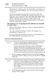
...the same COM port. See "Determining the COM port" on , set up properly but still does not transmit or receive data. The modem is on how to change these settings. Try making a test transmission to check this. NOTE To determine if your system's V.92 modem, visit the Toshiba Web site at... 300, 1200, 2400, 4800, 9600, 14400, 28800, 33600 bps (bits per second) or higher. 192 If Something Goes Wrong Resolving a hardware conflict Check the port settings to make sure the hardware and software are not familiar ...
...the same COM port. See "Determining the COM port" on , set up properly but still does not transmit or receive data. The modem is on how to change these settings. Try making a test transmission to check this. NOTE To determine if your system's V.92 modem, visit the Toshiba Web site at... 300, 1200, 2400, 4800, 9600, 14400, 28800, 33600 bps (bits per second) or higher. 192 If Something Goes Wrong Resolving a hardware conflict Check the port settings to make sure the hardware and software are not familiar ...
User Manual
Page 193
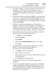
... other than the private address of 169.254.xxx.xxx assigned by plugging a standard CAT5 Ethernet patch cable (sold separately) into your computer's RJ45 Ethernet port. Toshiba provides a Client Manager utility for each active network adapter will be disrupted. ❖ Verify that the Service Set Identifier (SSID), or network name, is correct...
... other than the private address of 169.254.xxx.xxx assigned by plugging a standard CAT5 Ethernet patch cable (sold separately) into your computer's RJ45 Ethernet port. Toshiba provides a Client Manager utility for each active network adapter will be disrupted. ❖ Verify that the Service Set Identifier (SSID), or network name, is correct...
User Manual
Page 222
AC alternating current BIOS basic input/output system bps bits per second CD compact disc CD-ROM compact disc read-only memory CD-RW compact disc rewrite memory CMOS complementary metal-oxide semiconductor COM1 communications port 1 (serial port) COM2 communications port 2 (serial port) CPU central processing unit DC direct current DMA direct memory access DIMM dual inline memory module 222 Glossary TECHNICAL NOTE: Some features defined in this glossary may not be available on your computer. Acronyms The following acronyms may appear in this user's guide.
AC alternating current BIOS basic input/output system bps bits per second CD compact disc CD-ROM compact disc read-only memory CD-RW compact disc rewrite memory CMOS complementary metal-oxide semiconductor COM1 communications port 1 (serial port) COM2 communications port 2 (serial port) CPU central processing unit DC direct current DMA direct memory access DIMM dual inline memory module 222 Glossary TECHNICAL NOTE: Some features defined in this glossary may not be available on your computer. Acronyms The following acronyms may appear in this user's guide.


