User Manual
Page 2
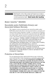
Model: Satellite ® M40/M45 Recordable and/or ReWritable Drive(s) and Associated Software Warranty The computer system you may include Recordable and/or ReWritable optical media drive(s) and associated software, among the most advanced data storage technologies available. Protection of Stored Data For your ...COPYING OR TRANSFERRING YOUR DATA, PLEASE BE SURE TO CONFIRM WHETHER THE DATA HAS BEEN SUCCESSFULLY COPIED OR TRANSFERRED. YOU AGREE THAT TOSHIBA, ITS AFFILIATES AND SUPPLIERS SHALL HAVE NO RESPONSIBILITY FOR DAMAGE TO OR LOSS OF ANY BUSINESS, PROFITS, PROGRAMS, DATA, NETWORK ...
Model: Satellite ® M40/M45 Recordable and/or ReWritable Drive(s) and Associated Software Warranty The computer system you may include Recordable and/or ReWritable optical media drive(s) and associated software, among the most advanced data storage technologies available. Protection of Stored Data For your ...COPYING OR TRANSFERRING YOUR DATA, PLEASE BE SURE TO CONFIRM WHETHER THE DATA HAS BEEN SUCCESSFULLY COPIED OR TRANSFERRED. YOU AGREE THAT TOSHIBA, ITS AFFILIATES AND SUPPLIERS SHALL HAVE NO RESPONSIBILITY FOR DAMAGE TO OR LOSS OF ANY BUSINESS, PROFITS, PROGRAMS, DATA, NETWORK ...
User Manual
Page 25
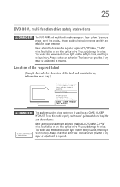
... user's guide carefully and keep it for future reference. You could damage the drive. Never attempt to laser light or other optical drive. To ensure proper use this instruction manual carefully and retain for your future reference. Always contact an authorized Toshiba service provider, if any repair or adjustment is required. Location of the...
... user's guide carefully and keep it for future reference. You could damage the drive. Never attempt to laser light or other optical drive. To ensure proper use this instruction manual carefully and retain for your future reference. Always contact an authorized Toshiba service provider, if any repair or adjustment is required. Location of the...
User Manual
Page 88
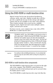
... fourth change, the region will allow you play in ." 88 Learning the Basics Using the DVD-ROM or multi-function drive Using the DVD-ROM or multi-function drive Optical storage has become the preferred medium for software, music, and video. NOTE For optimum CD and DVD performance, it is... located on any other region. DVD-ROM or multi-function drive components The DVD-ROM or multi-function drive is recommended that are ...
... fourth change, the region will allow you play in ." 88 Learning the Basics Using the DVD-ROM or multi-function drive Using the DVD-ROM or multi-function drive Optical storage has become the preferred medium for software, music, and video. NOTE For optimum CD and DVD performance, it is... located on any other region. DVD-ROM or multi-function drive components The DVD-ROM or multi-function drive is recommended that are ...

User Manual
Page 250
... permits a computer to the computer. CPU - cursor - device driver - See also enable. CPU cache - Printers, disk drives, and modems are examples of the cursor varies, depending on the program you are using and what you are doing. Compare alternating...L2 cache. See folder. For example, disk drives, monitors, keyboards, and printers all require controllers. The shape of devices. The setting selected by optical (laser) technology, and used in one direction. device - disable - A section of optical discs, such as CDs and DVDs. direct memory...
... permits a computer to the computer. CPU - cursor - device driver - See also enable. CPU cache - Printers, disk drives, and modems are examples of the cursor varies, depending on the program you are using and what you are doing. Compare alternating...L2 cache. See folder. For example, disk drives, monitors, keyboards, and printers all require controllers. The shape of devices. The setting selected by optical (laser) technology, and used in one direction. device - disable - A section of optical discs, such as CDs and DVDs. direct memory...

Maintenance Manual
Page 7
... 2.5 Keyboard Troubleshooting 2-15 2.6 External USB Devices Troubleshooting 2-17 2.7 TV-Out Failure Troubleshooting 2-19 2.8 Printer Port Troubleshooting 2-21 2.9 TouchPad Troubleshooting 2-23 2.10 Speaker Troubleshooting 2-25 2.11 Optical Drive Troubleshooting 2-27 2.12 Modem Troubleshooting 2-30 2.13 PCMCIA Troubleshooting 2-32 2.14 IEEE 1394 Troubleshooting 2-34 2.15 Wireless LAN Troubleshooting 2-36 Satellite M40X Maintenance Manual [CONFIDENTIAL] vii
... 2.5 Keyboard Troubleshooting 2-15 2.6 External USB Devices Troubleshooting 2-17 2.7 TV-Out Failure Troubleshooting 2-19 2.8 Printer Port Troubleshooting 2-21 2.9 TouchPad Troubleshooting 2-23 2.10 Speaker Troubleshooting 2-25 2.11 Optical Drive Troubleshooting 2-27 2.12 Modem Troubleshooting 2-30 2.13 PCMCIA Troubleshooting 2-32 2.14 IEEE 1394 Troubleshooting 2-34 2.15 Wireless LAN Troubleshooting 2-36 Satellite M40X Maintenance Manual [CONFIDENTIAL] vii

Maintenance Manual
Page 9
Chapter 4 Replacement Procedures 4.1 General...4-1 4.2 Battery...4-7 4.3 PC Card...4-9 4.4 HDD ...4-11 4.5 Optical Drive Module...4-13 4.6 Optical Drive ...4-15 4.7 Wireless LAN Unit ...4-17 4.8 Expansion Memory...4-20 4.9 Keyboard ...4-23 4.10 Modem...4-26 4.11 Display Assembly...4-28 4.12 Touch Cover...4-31 4.13 Touch Pad ...4-34 4.14 Speakers ...4-36 4.15 System Board ...4-37 4.16 Fan, Heat Sink, & CPU 4-39 4.17 Display Mask...4-42 4.18 LCD Module ...4-44 4.19 FL Inverter Board...4-47 Satellite M40X Maintenance Manual [CONFIDENTIAL] ix
Chapter 4 Replacement Procedures 4.1 General...4-1 4.2 Battery...4-7 4.3 PC Card...4-9 4.4 HDD ...4-11 4.5 Optical Drive Module...4-13 4.6 Optical Drive ...4-15 4.7 Wireless LAN Unit ...4-17 4.8 Expansion Memory...4-20 4.9 Keyboard ...4-23 4.10 Modem...4-26 4.11 Display Assembly...4-28 4.12 Touch Cover...4-31 4.13 Touch Pad ...4-34 4.14 Speakers ...4-36 4.15 System Board ...4-37 4.16 Fan, Heat Sink, & CPU 4-39 4.17 Display Mask...4-42 4.18 LCD Module ...4-44 4.19 FL Inverter Board...4-47 Satellite M40X Maintenance Manual [CONFIDENTIAL] ix

Maintenance Manual
Page 32
... Troubleshooting 2-17 2.7 TV-Out Failure Troubleshooting 2-19 2.8 Printer Port Troubleshooting 2-21 2.9 TouchPad Troubleshooting 2-23 2.10 Speaker Troubleshooting 2-25 2.11 Optical Drive Troubleshooting 2-27 2.12 Modem Troubleshooting 2-30 2.13 PCMCIA Troubleshooting 2-32 2.14 IEEE 1394 Troubleshooting 2-34 2.16 Wireless LAN Troubleshooting 2-36 Satellite M40X/M45X/Satellite Pro M40X/EQUIUM M40X Series Maintenance Manual [CONFIDENTIAL] 2-iii
... Troubleshooting 2-17 2.7 TV-Out Failure Troubleshooting 2-19 2.8 Printer Port Troubleshooting 2-21 2.9 TouchPad Troubleshooting 2-23 2.10 Speaker Troubleshooting 2-25 2.11 Optical Drive Troubleshooting 2-27 2.12 Modem Troubleshooting 2-30 2.13 PCMCIA Troubleshooting 2-32 2.14 IEEE 1394 Troubleshooting 2-34 2.16 Wireless LAN Troubleshooting 2-36 Satellite M40X/M45X/Satellite Pro M40X/EQUIUM M40X Series Maintenance Manual [CONFIDENTIAL] 2-iii

Maintenance Manual
Page 33
... process 2-21 TouchPad troubleshooting process 2-23 Speaker troubleshooting process 2-25 Optical drive troubleshooting process 2-27 Modem troubleshooting process 2-30 PCMCIA troubleshooting process 2-32 IEEE 1394 troubleshooting process 2-34 Wireless LAN troubleshooting process 2-36 Tables Table 2-1 Battery LED...2-8 Table 2-2 DC-IN LED ...2-9 2-iv [CONFIDENTIAL] Satellite M40X/M45X/Satellite Pro M40X/EQUIUM M40X Series Maintenance Manual l
... process 2-21 TouchPad troubleshooting process 2-23 Speaker troubleshooting process 2-25 Optical drive troubleshooting process 2-27 Modem troubleshooting process 2-30 PCMCIA troubleshooting process 2-32 IEEE 1394 troubleshooting process 2-34 Wireless LAN troubleshooting process 2-36 Tables Table 2-1 Battery LED...2-8 Table 2-2 DC-IN LED ...2-9 2-iv [CONFIDENTIAL] Satellite M40X/M45X/Satellite Pro M40X/EQUIUM M40X Series Maintenance Manual l

Maintenance Manual
Page 34
... formatted work disk for optical drive troubleshooting 9. Cleaning kit for floppy disk drive testing 5. USB test module and USB cable 15. TV-out port 10. Modem The Diagnostics Disk operations are given in Chapter 3. The following tools are : 1. Multimeter 10. Multimedia sound system with line- Music CD Satellite M40X/M45X/Satellite Pro M40X/EQUIUM M40X...
... formatted work disk for optical drive troubleshooting 9. Cleaning kit for floppy disk drive testing 5. USB test module and USB cable 15. TV-out port 10. Modem The Diagnostics Disk operations are given in Chapter 3. The following tools are : 1. Multimeter 10. Multimedia sound system with line- Music CD Satellite M40X/M45X/Satellite Pro M40X/EQUIUM M40X...

Maintenance Manual
Page 38
The test program should be intermittent. Satellite M40X/M45X/Satellite Pro M40X/EQUIUM M40X Series Maintenance Manual [CONFIDENTIAL] 2-5 When a problem has been located, perform the appropriate troubleshooting procedures as follows: 1. If ... Troubleshooting procedures in Section 2.12. If an error is detected by the audio test, perform the Speaker Troubleshooting procedures in Section 2.10 and the Optical Drive Troubleshooting Procedures in Section 2.5. 4. If an error is detected by the keyboard test, perform the Keyboard Troubleshooting procedures in Section 2.12. 7. If...
The test program should be intermittent. Satellite M40X/M45X/Satellite Pro M40X/EQUIUM M40X Series Maintenance Manual [CONFIDENTIAL] 2-5 When a problem has been located, perform the appropriate troubleshooting procedures as follows: 1. If ... Troubleshooting procedures in Section 2.12. If an error is detected by the audio test, perform the Speaker Troubleshooting procedures in Section 2.10 and the Optical Drive Troubleshooting Procedures in Section 2.5. 4. If an error is detected by the keyboard test, perform the Keyboard Troubleshooting procedures in Section 2.12. 7. If...

Maintenance Manual
Page 60
No cleaning check (Procedure 2) Yes Perform software check (Procedure 3) Perform diagnostic test (Procedure 4) Perform connection and replacement check (Procedure 5) Replace system board END Figure 2-10 Optical drive troubleshooting process Satellite M40X/M45X/Satellite Pro M40X/EQUIUM M40X Series Maintenance Manual [CONFIDENTIAL] 2-27 Perform drive- 2.11 Optical Drive Troubleshooting 2.11 Optical Drive Troubleshooting START Perform audio CD check (Procedure 1) 2 Troubleshooting Procedures Audio CD functions ok?
No cleaning check (Procedure 2) Yes Perform software check (Procedure 3) Perform diagnostic test (Procedure 4) Perform connection and replacement check (Procedure 5) Replace system board END Figure 2-10 Optical drive troubleshooting process Satellite M40X/M45X/Satellite Pro M40X/EQUIUM M40X Series Maintenance Manual [CONFIDENTIAL] 2-27 Perform drive- 2.11 Optical Drive Troubleshooting 2.11 Optical Drive Troubleshooting START Perform audio CD check (Procedure 1) 2 Troubleshooting Procedures Audio CD functions ok?

Maintenance Manual
Page 61
... occur while executing the diagnostic program, go to Procedure 5. 2-28 [CONFIDENTIAL] Satellite M40X/M45X/Satellite Pro M40X/EQUIUM M40X Series Maintenance Manual If it works, the problem is functioning properly. DVD-ROM device ? The Satellite P10 module bays can accommodate the following optical drives: ? COMBO device Figure 2-11 outlines the process. Perform the steps below...
... occur while executing the diagnostic program, go to Procedure 5. 2-28 [CONFIDENTIAL] Satellite M40X/M45X/Satellite Pro M40X/EQUIUM M40X Series Maintenance Manual If it works, the problem is functioning properly. DVD-ROM device ? The Satellite P10 module bays can accommodate the following optical drives: ? COMBO device Figure 2-11 outlines the process. Perform the steps below...

Maintenance Manual
Page 62
...Optical Drive Troubleshooting 2 Troubleshooting Procedures Procedure 5 Connection check and replacement check The optical drive connects to Check 2. Check 2 The drive or drive cable may be damaged. Replace it with a new one following the instructions in Chapter 4, Replacement Procedures, and perform the following checks: Check 1 Make sure the drive is still not functioning properly, perform Check 3. The drive... be defective or damaged. Satellite M40X/M45X/Satellite Pro M40X/EQUIUM M40X Series Maintenance Manual [CONFIDENTIAL] 2-29 If the drive is firmly connected to the...
...Optical Drive Troubleshooting 2 Troubleshooting Procedures Procedure 5 Connection check and replacement check The optical drive connects to Check 2. Check 2 The drive or drive cable may be damaged. Replace it with a new one following the instructions in Chapter 4, Replacement Procedures, and perform the following checks: Check 1 Make sure the drive is still not functioning properly, perform Check 3. The drive... be defective or damaged. Satellite M40X/M45X/Satellite Pro M40X/EQUIUM M40X Series Maintenance Manual [CONFIDENTIAL] 2-29 If the drive is firmly connected to the...

Maintenance Manual
Page 105
4 Replacement Procedures Chapter 4 Contents 4.1 General...4-1 4.2 Battery...4-7 4.3 PC Card...4-9 4.4 HDD...4-11 4.5 Optical Drive Module ...4-13 4.6 Optical Drive...4-15 4.7 Keyboard...4-17 4.8 Wireless LAN Unit ...4-20 4.9 Expansion Memory...4-22 4.10 Modem ...4-25 4.11 Display Assembly ...4-27 4.12 Top Cover ...4-30 4.13 Touch Pad ...4-33 4.14 Speakers ...4-35 4.15 System Board ...4-36 4.16 Fan & CPU...4-38 4.17 Display Mask ...4-41 4.18 LCD Module ...4-43 4.19 FL Inverter Board ...4-46 Satellite M40X Series Maintenance Manual [CONFIDENTIAL] 4-iii
4 Replacement Procedures Chapter 4 Contents 4.1 General...4-1 4.2 Battery...4-7 4.3 PC Card...4-9 4.4 HDD...4-11 4.5 Optical Drive Module ...4-13 4.6 Optical Drive...4-15 4.7 Keyboard...4-17 4.8 Wireless LAN Unit ...4-20 4.9 Expansion Memory...4-22 4.10 Modem ...4-25 4.11 Display Assembly ...4-27 4.12 Top Cover ...4-30 4.13 Touch Pad ...4-33 4.14 Speakers ...4-35 4.15 System Board ...4-36 4.16 Fan & CPU...4-38 4.17 Display Mask ...4-41 4.18 LCD Module ...4-43 4.19 FL Inverter Board ...4-46 Satellite M40X Series Maintenance Manual [CONFIDENTIAL] 4-iii

Maintenance Manual
Page 106
... 4-2 Pressing the eject button 4-9 Figure 4-3 Installing the PC card 4-10 Figure 4-4 HDD ...4-11 Figure 4-5 Removing the HDD door 4-11 Figure 4-6 Removing the optical drive module 4-13 Figure 4-7 Removing the optical drive bracket 4-15 Figure 4-8 Removing the strip cover 4-17 Figure 4-9 Removing the keyboard 4-18 Figure 4-10 Disconnecting the keyboard cable 4-18 Figure 4-11 Removing...hexagonal screws 4-36 Figure 4-25 Removing the system board 4-36 Figure 4-26 Removing the fan module 4-39 Figure 4-27 Removing the CPU 4-39 4-iv [CONFIDENTIAL] Satellite M40X Series Maintenance Manual
... 4-2 Pressing the eject button 4-9 Figure 4-3 Installing the PC card 4-10 Figure 4-4 HDD ...4-11 Figure 4-5 Removing the HDD door 4-11 Figure 4-6 Removing the optical drive module 4-13 Figure 4-7 Removing the optical drive bracket 4-15 Figure 4-8 Removing the strip cover 4-17 Figure 4-9 Removing the keyboard 4-18 Figure 4-10 Disconnecting the keyboard cable 4-18 Figure 4-11 Removing...hexagonal screws 4-36 Figure 4-25 Removing the system board 4-36 Figure 4-26 Removing the fan module 4-39 Figure 4-27 Removing the CPU 4-39 4-iv [CONFIDENTIAL] Satellite M40X Series Maintenance Manual

Maintenance Manual
Page 120
Use your hand to remove the keyboard first. Figure 4-6 Removing the optical drive module Satellite M40X Series Maintenance Manual [CONFIDENTIAL] 4-13 4 Replacement Procedures 4.5 Optical Drive Module Removing the Optical Drive Module To remove the optical drive module, you need to push the module and then you can slide the module from the bay. Follow the steps below: 1. Turn the computer upside down. 2. Remove the screw M2.5x5 securing the optical drive module. 3.
Use your hand to remove the keyboard first. Figure 4-6 Removing the optical drive module Satellite M40X Series Maintenance Manual [CONFIDENTIAL] 4-13 4 Replacement Procedures 4.5 Optical Drive Module Removing the Optical Drive Module To remove the optical drive module, you need to push the module and then you can slide the module from the bay. Follow the steps below: 1. Turn the computer upside down. 2. Remove the screw M2.5x5 securing the optical drive module. 3.

Maintenance Manual
Page 121
Slide the device into the optical drive module bay. 2. 4 Replacement Procedures Installing the Optical Drive Module To install a device in the optical drive module bay, follow the steps below and refer to secure the optical drive module. 4-14 [CONFIDENTIAL] Satellite M40X Series Maintenance Manual Use the screw M2.5x5 to the figure in the preceding section. 1.
Slide the device into the optical drive module bay. 2. 4 Replacement Procedures Installing the Optical Drive Module To install a device in the optical drive module bay, follow the steps below and refer to secure the optical drive module. 4-14 [CONFIDENTIAL] Satellite M40X Series Maintenance Manual Use the screw M2.5x5 to the figure in the preceding section. 1.

Maintenance Manual
Page 122
4 Replacement Procedures 4.6 Optical Drive This computer may be fitted with a: CD-RW/DVD-ROM device DVD dual device DVD Super Multi device Disassembling the Optical Drive To disassemble the optical drive, first remove the drive from the bay. 2. Remove one M2.5x5 screw and slide the optical drive module from its module bay, then follow the steps below. 1. Remove two M2x3 screws from the bracket plate. Figure 4-7 Removing the optical drive bracket Satellite M40X Series Maintenance Manual [CONFIDENTIAL] 4-15 Remove the bracket plate.
4 Replacement Procedures 4.6 Optical Drive This computer may be fitted with a: CD-RW/DVD-ROM device DVD dual device DVD Super Multi device Disassembling the Optical Drive To disassemble the optical drive, first remove the drive from the bay. 2. Remove one M2.5x5 screw and slide the optical drive module from its module bay, then follow the steps below. 1. Remove two M2x3 screws from the bracket plate. Figure 4-7 Removing the optical drive bracket Satellite M40X Series Maintenance Manual [CONFIDENTIAL] 4-15 Remove the bracket plate.

Maintenance Manual
Page 123
Install the optical drive module into the bay and secure with two black M2×3 screws. 3. Position the optical drive bracket plate to the figure in the preceding section. 1. Secure the optical drive bracket plate with one M2.5x5 screw. 4-16 [CONFIDENTIAL] Satellite M40X Series Maintenance Manual 4 Replacement Procedures Reassembling the Optical Drive To reassemble an optical drive, follow the steps below and refer to the rear panel of optical drive. 2.
Install the optical drive module into the bay and secure with two black M2×3 screws. 3. Position the optical drive bracket plate to the figure in the preceding section. 1. Secure the optical drive bracket plate with one M2.5x5 screw. 4-16 [CONFIDENTIAL] Satellite M40X Series Maintenance Manual 4 Replacement Procedures Reassembling the Optical Drive To reassemble an optical drive, follow the steps below and refer to the rear panel of optical drive. 2.

Maintenance Manual
Page 137
...upside down and remove the following twenty one screws. (M2.5X5fifteen screws, M2.5X10-four screws, and M2.5x3-three screws) 4-30 [CONFIDENTIAL] Satellite M40X Series Maintenance Manual Remove modem and wireless LAN covers. 2. Detach the upper FFC cable and touch pad FPC cable on the top chassis. 4. Figure... securing top cover. 4 Replacement Procedures 4.12 Top Cover Removing the Cover To remove the top cover, first remove the battery pack, display assembly, optical drive module, HDD, and memory module and wireless LAN as described in the preceding sections, then follow the steps below: 1.
...upside down and remove the following twenty one screws. (M2.5X5fifteen screws, M2.5X10-four screws, and M2.5x3-three screws) 4-30 [CONFIDENTIAL] Satellite M40X Series Maintenance Manual Remove modem and wireless LAN covers. 2. Detach the upper FFC cable and touch pad FPC cable on the top chassis. 4. Figure... securing top cover. 4 Replacement Procedures 4.12 Top Cover Removing the Cover To remove the top cover, first remove the battery pack, display assembly, optical drive module, HDD, and memory module and wireless LAN as described in the preceding sections, then follow the steps below: 1.


