
User Guide
Page 2
... ANY TROUBLE, FAILURE OR MALFUNCTION OF THE HARD DISK DRIVE OR OTHER STORAGE DEVICES AND THE DATA CANNOT BE RECOVERED, TOSHIBA SHALL NOT BE LIABLE FOR ANY DAMAGE OR LOSS OF DATA, OR ANY OTHER DAMAGE RESULTING THEREFROM. TOSHIBA DISCLAIMS ANY LIABILITY FOR THE FAILURE TO COPY OR TRANSFER THE DATA CORRECTLY. Model: Portégé® R500 Series Recordable and/or ReWritable Drive(s) and Associated Software Warranty The...
... ANY TROUBLE, FAILURE OR MALFUNCTION OF THE HARD DISK DRIVE OR OTHER STORAGE DEVICES AND THE DATA CANNOT BE RECOVERED, TOSHIBA SHALL NOT BE LIABLE FOR ANY DAMAGE OR LOSS OF DATA, OR ANY OTHER DAMAGE RESULTING THEREFROM. TOSHIBA DISCLAIMS ANY LIABILITY FOR THE FAILURE TO COPY OR TRANSFER THE DATA CORRECTLY. Model: Portégé® R500 Series Recordable and/or ReWritable Drive(s) and Associated Software Warranty The...
User Guide
Page 5
... you in a margin at (949) 859-4273. Contact the state public utility commission, public service commission or corporation commission for repair or limited warranty information, please contact Toshiba Corporation, Toshiba America Information Systems, Inc. If Problems Arise If this computer. or an authorized representative of Toshiba, or the Toshiba Support Centre within the United States at (800) 457-7777 or Outside the...
... you in a margin at (949) 859-4273. Contact the state public utility commission, public service commission or corporation commission for repair or limited warranty information, please contact Toshiba Corporation, Toshiba America Information Systems, Inc. If Problems Arise If this computer. or an authorized representative of Toshiba, or the Toshiba Support Centre within the United States at (800) 457-7777 or Outside the...

User Guide
Page 31
... 129 Installing SD card drivers 130 Inserting an SD card 130 Formatting an SD card 131 Using Standby or Hibernate while using the SD card 131 Removing an SD card 131 Using the i.LINK® port 132 Using an expansion device 133 Using an Optional Toshiba Slim Port Replicator II with your computer.......133 Chapter 5: Utilities 134 TOSHIBA Assist 135 Connect 136 Secure 137 Protect...
... 129 Installing SD card drivers 130 Inserting an SD card 130 Formatting an SD card 131 Using Standby or Hibernate while using the SD card 131 Removing an SD card 131 Using the i.LINK® port 132 Using an expansion device 133 Using an Optional Toshiba Slim Port Replicator II with your computer.......133 Chapter 5: Utilities 134 TOSHIBA Assist 135 Connect 136 Secure 137 Protect...
User Guide
Page 50
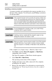
... Hibernation mode, data will need a small Phillips screwdriver for this procedure. The Turn off the computer using the Start menu. You will be installed in good condition. Avoid touching the cover, the module, and the surrounding area before replacing it. Failure to step 3. 1 Click Start, and then Turn off the computer. 3 Unplug and remove any cables connected to room temperature before...
... Hibernation mode, data will need a small Phillips screwdriver for this procedure. The Turn off the computer using the Start menu. You will be installed in good condition. Avoid touching the cover, the module, and the surrounding area before replacing it. Failure to step 3. 1 Click Start, and then Turn off the computer. 3 Unplug and remove any cables connected to room temperature before...

User Guide
Page 145
Deleting a user password To cancel the power-on -screen instructions to remove the user password. The TOSHIBA Assist window appears. 2 On the left side, click the Secure tab. 3 Click the User Password icon. 4 Click Delete. 5 Follow the on password function: 1 Click Start, All Programs, Toshiba, Utilities, and then TOSHIBA Assist. TOSHIBA Security Assist The TOSHIBA Security Assist Utility acts as a "command center" where you protect your system. Utilities TOSHIBA Security Assist 145 4 Click Set. 5 Enter your password, and...
Deleting a user password To cancel the power-on -screen instructions to remove the user password. The TOSHIBA Assist window appears. 2 On the left side, click the Secure tab. 3 Click the User Password icon. 4 Click Delete. 5 Follow the on password function: 1 Click Start, All Programs, Toshiba, Utilities, and then TOSHIBA Assist. TOSHIBA Security Assist The TOSHIBA Security Assist Utility acts as a "command center" where you protect your system. Utilities TOSHIBA Security Assist 145 4 Click Set. 5 Enter your password, and...
User Guide
Page 172
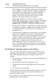
... as installing a new program or adding a device. The voltage level must be a problem with the desktop and used to the way the operating system responds to a different power outlet, preferably in a different room. The amperage rating of these problems, use the options in the Startup menu to or greater than the computer requires, even if the rated voltage is rated for your computer model. The...
... as installing a new program or adding a device. The voltage level must be a problem with the desktop and used to the way the operating system responds to a different power outlet, preferably in a different room. The amperage rating of these problems, use the options in the Startup menu to or greater than the computer requires, even if the rated voltage is rated for your computer model. The...
User Guide
Page 192
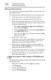
... your computer recognizes your optical drive by double-clicking the My Computer icon on optical drives and their operation. A blank screen appears while watching a DVD-ROM movie or title. To verify your drive to an authorized service provider to 24-bit color, there may be a video format error. Disable the Shut off Monitor feature in the Display Properties using Device Manager...
... your computer recognizes your optical drive by double-clicking the My Computer icon on optical drives and their operation. A blank screen appears while watching a DVD-ROM movie or title. To verify your drive to an authorized service provider to 24-bit color, there may be a video format error. Disable the Shut off Monitor feature in the Display Properties using Device Manager...

User Guide
Page 232
... AC adaptor to the computer when using the USB Sleep and charge function. ❖ External devices connected to the USB bus power (DC5V) function that you must change Disabled to Enabled in the BIOS Setup. ❖ When "USB Sleep and Charge function" is set to Enabled in the default setting. As such, we recommend that interfaces with their own chargers. ❖ If external devices are connected to compatible ports when the AC adaptor is...
... AC adaptor to the computer when using the USB Sleep and charge function. ❖ External devices connected to the USB bus power (DC5V) function that you must change Disabled to Enabled in the BIOS Setup. ❖ When "USB Sleep and Charge function" is set to Enabled in the default setting. As such, we recommend that interfaces with their own chargers. ❖ If external devices are connected to compatible ports when the AC adaptor is...
User Guide
Page 253
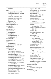
... power up 170 contacting Toshiba 200 corrupted/damaged data files 184 Device Manager 176 disabling a device 177 disk drive is slow 183 display is blank 181 external display not working 182 external monitor 181 faulty memory 178 hardware conflict 174, 175 high-pitched noise 186 illegal operation 169 Internet bookmarked site not found 174 Internet connection is slow 174 keyboard not responding 170 missing files/trouble accessing a disk...
... power up 170 contacting Toshiba 200 corrupted/damaged data files 184 Device Manager 176 disabling a device 177 disk drive is slow 183 display is blank 181 external display not working 182 external monitor 181 faulty memory 178 hardware conflict 174, 175 high-pitched noise 186 illegal operation 169 Internet bookmarked site not found 174 Internet connection is slow 174 keyboard not responding 170 missing files/trouble accessing a disk...
Maintenance Manual
Page 3
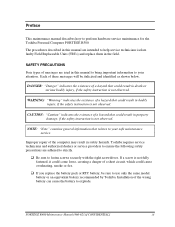
... service technicians isolate faulty Field Replaceable Units (FRUs) and replace them in this manual to bring important information to perform hardware service maintenance for the Toshiba Personal Computer PORTÉGÉ R500. Installation of a hazard that relates to fasten screws securely with the right screwdriver. The procedures described in the field. Improper repair of messages are used in safety hazards. SAFETY PRECAUTIONS Four types...
... service technicians isolate faulty Field Replaceable Units (FRUs) and replace them in this manual to bring important information to perform hardware service maintenance for the Toshiba Personal Computer PORTÉGÉ R500. Installation of a hazard that relates to fasten screws securely with the right screwdriver. The procedures described in the field. Improper repair of messages are used in safety hazards. SAFETY PRECAUTIONS Four types...
Maintenance Manual
Page 7
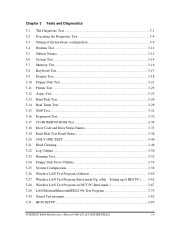
... Test ...3-25 3.13 Hard Disk Test ...3-26 3.14 Real Timer Test...3-29 3.15 NDP Test...3-31 3.16 Expansion Test...3-32 3.17 CD-ROM/DVD-ROM Test 3-34 3.18 Error Code and Error Status Names 3-35 3.19 Hard Disk Test Detail Status 3-38 3.20 ONLY ONE TEST 3-40 3.21 Head Cleaning...3-49 3.22 Log Utilities ...3-50 3.23 Running Test...3-52 3.24 Floppy Disk Drive Utilities 3-53 3.25 System Configuration 3-58 3.26 Wireless LAN Test...
... Test ...3-25 3.13 Hard Disk Test ...3-26 3.14 Real Timer Test...3-29 3.15 NDP Test...3-31 3.16 Expansion Test...3-32 3.17 CD-ROM/DVD-ROM Test 3-34 3.18 Error Code and Error Status Names 3-35 3.19 Hard Disk Test Detail Status 3-38 3.20 ONLY ONE TEST 3-40 3.21 Head Cleaning...3-49 3.22 Log Utilities ...3-50 3.23 Running Test...3-52 3.24 Floppy Disk Drive Utilities 3-53 3.25 System Configuration 3-58 3.26 Wireless LAN Test...

Maintenance Manual
Page 53
2.3 Power Supply Troubleshooting 2 Troubleshooting Procedures Procedure 2 Error Code Check If the power supply microprocessor detects a malfunction, it indicates the error code as shown below. Where Error occurs PORTEGE R500 Maintenance Manual (960-634) [CONFIDENTIAL] 2-7 Table 2-3 Error code Error code 1*h 2*h 3*h 4*h 5*h 6*h 7*h 8*h 9*h A*h B*h C*h D*h E*h F*h AC Adaptor 1st Battery 2nd Battery S3V output E5V output E3V output 1R5-E1V output 1R8-B1V output PPV output PTV output 1R5-E1V output ...
2.3 Power Supply Troubleshooting 2 Troubleshooting Procedures Procedure 2 Error Code Check If the power supply microprocessor detects a malfunction, it indicates the error code as shown below. Where Error occurs PORTEGE R500 Maintenance Manual (960-634) [CONFIDENTIAL] 2-7 Table 2-3 Error code Error code 1*h 2*h 3*h 4*h 5*h 6*h 7*h 8*h 9*h A*h B*h C*h D*h E*h F*h AC Adaptor 1st Battery 2nd Battery S3V output E5V output E3V output 1R5-E1V output 1R8-B1V output PPV output PTV output 1R5-E1V output ...

Maintenance Manual
Page 57
... correctly installed in the computer. If the error still exists, go to the following step: ‰ Replace the battery pack with a new one. Check 3 In the case of error code 10h or 12h: ‰ Make sure the AC adaptor cord and AC power cord are connected correctly, go to Procedure 5. E2h PTV voltage is under 0.89V when the computer is powered on /off. 2.3 Power Supply Troubleshooting 2 Troubleshooting Procedures...
... correctly installed in the computer. If the error still exists, go to the following step: ‰ Replace the battery pack with a new one. Check 3 In the case of error code 10h or 12h: ‰ Make sure the AC adaptor cord and AC power cord are connected correctly, go to Procedure 5. E2h PTV voltage is under 0.89V when the computer is powered on /off. 2.3 Power Supply Troubleshooting 2 Troubleshooting Procedures...
Maintenance Manual
Page 109
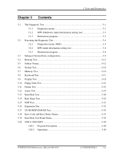
... Diagnostic Test 3-4 3.2.1 Diagnostics menu (T&D 3-5 3.2.2 H/W initial information setting tool 3-8 3.2.3 Heatrun test program 3-8 3.3 Setting of the hardware configuration 3-9 3.4 Heatrun Test...3-11 3.5 Subtest Names...3-12 3.6 System Test...3-14 3.7 Memory Test...3-16 3.8 Keyboard Test...3-17 3.9 Display Test ...3-18 3.10 Floppy Disk Test...3-21 3.11 Printer Test...3-23 3.12 Async Test ...3-25 3.13 Hard Disk Test ...3-26 3.14 Real Timer Test...3-29 3.15 NDP Test...3-31 3.16 Expansion Test...3-32 3.17 CD-ROM/DVD-ROM Test 3-34 3.18 Error Code and Error...
... Diagnostic Test 3-4 3.2.1 Diagnostics menu (T&D 3-5 3.2.2 H/W initial information setting tool 3-8 3.2.3 Heatrun test program 3-8 3.3 Setting of the hardware configuration 3-9 3.4 Heatrun Test...3-11 3.5 Subtest Names...3-12 3.6 System Test...3-14 3.7 Memory Test...3-16 3.8 Keyboard Test...3-17 3.9 Display Test ...3-18 3.10 Floppy Disk Test...3-21 3.11 Printer Test...3-23 3.12 Async Test ...3-25 3.13 Hard Disk Test ...3-26 3.14 Real Timer Test...3-29 3.15 NDP Test...3-31 3.16 Expansion Test...3-32 3.17 CD-ROM/DVD-ROM Test 3-34 3.18 Error Code and Error...
Maintenance Manual
Page 120
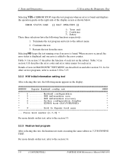
...menu appears in section 3.5 describes the function of each error. Table 3-2 in DIAGNOSTIC TEST MENU are described on and after section 3.6. Press test number [1-5,9] ? 3 Tests and Diagnostics 3.2 Executing the Diagnostic Test Selecting YES of ERROR STOP stops the test program when an error is found . Table 3-1 in the display. ###### Repair Initial config set #### * 1 Initial configuration * * 2 DMI information save * * 3 DMI information recovery * * 4 System configuration display * * 5 E2PROM test (MAC/GUID/DMI) * * * * 9 Exit to the subtest menu...
...menu appears in section 3.5 describes the function of each error. Table 3-2 in DIAGNOSTIC TEST MENU are described on and after section 3.6. Press test number [1-5,9] ? 3 Tests and Diagnostics 3.2 Executing the Diagnostic Test Selecting YES of ERROR STOP stops the test program when an error is found . Table 3-1 in the display. ###### Repair Initial config set #### * 1 Initial configuration * * 2 DMI information save * * 3 DMI information recovery * * 4 System configuration display * * 5 E2PROM test (MAC/GUID/DMI) * * * * 9 Exit to the subtest menu...
Maintenance Manual
Page 147
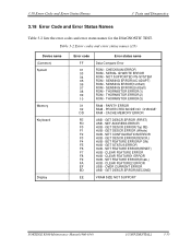
... ERROR(3) RAM - CACHE MEMORY ERROR USB - SET ADDRESS ERROR HUB - GET DESCR.ERROR(DESCR.) HUB - 3.18 Error Code and Error Status Names 3 Tests and Diagnostics 3.18 Error Code and Error Status Names Table 3-2 lists the error codes and error status names for the DIAGNOSTIC TEST. NOT SUPPORTED PS-SYSTEM ROM - SENSING ERROR(AC-ADAPT) ROM - SENSING ERROR(1st Batt) ROM - GET STATUS ERROR HUB - CLEAR FEATURE1 ERROR HUB - GET DESCR.ERROR(SECOND) VRAM SIZE NOT SUPPORT PORTEGE R500 Maintenance Manual (960...
... ERROR(3) RAM - CACHE MEMORY ERROR USB - SET ADDRESS ERROR HUB - GET DESCR.ERROR(DESCR.) HUB - 3.18 Error Code and Error Status Names 3 Tests and Diagnostics 3.18 Error Code and Error Status Names Table 3-2 lists the error codes and error status names for the DIAGNOSTIC TEST. NOT SUPPORTED PS-SYSTEM ROM - SENSING ERROR(AC-ADAPT) ROM - SENSING ERROR(1st Batt) ROM - GET STATUS ERROR HUB - CLEAR FEATURE1 ERROR HUB - GET DESCR.ERROR(SECOND) VRAM SIZE NOT SUPPORT PORTEGE R500 Maintenance Manual (960...

Maintenance Manual
Page 148
... - TIME OUT ERROR FIR - DRIVE NOT INITIALIZE HDD - ECC RECOVER ENABLE HDD - MEDIA REMOVED FDD - DMA BOUNDARY ERROR HDD - UNDEFINED ERROR HDD - RECORD NOT FOUND ERROR HDD - SEEK ERROR FDD - OUT OF PAPER PRT - LINE STATUS ERROR RS232C - TIME OUT ERROR HDD - RECORD NOT FOUND FDD - TIME OUT ERROR FDD - FAULT PRT - FRAMING ERROR RS232C - OVERRUN ERROR RS232C - BAD COMMAND ERROR HDD - HDC ERROR HDD - 3 Tests and Diagnostics 3.18 Error Code and Error Status Names Table 3-2 Error codes and error status names (2/3) Device name FDD Printer ASYNC HDD Error code...
... - TIME OUT ERROR FIR - DRIVE NOT INITIALIZE HDD - ECC RECOVER ENABLE HDD - MEDIA REMOVED FDD - DMA BOUNDARY ERROR HDD - UNDEFINED ERROR HDD - RECORD NOT FOUND ERROR HDD - SEEK ERROR FDD - OUT OF PAPER PRT - LINE STATUS ERROR RS232C - TIME OUT ERROR HDD - RECORD NOT FOUND FDD - TIME OUT ERROR FDD - FAULT PRT - FRAMING ERROR RS232C - OVERRUN ERROR RS232C - BAD COMMAND ERROR HDD - HDC ERROR HDD - 3 Tests and Diagnostics 3.18 Error Code and Error Status Names Table 3-2 Error codes and error status names (2/3) Device name FDD Printer ASYNC HDD Error code...

Maintenance Manual
Page 149
... - CONTROL WORD ERROR NDP - STATUS WORD ERROR NDP - ACCESS TIME ERROR HDD - WRITE FAULT HDD - MULTIPLAY ERROR ADDRESS LINE ERROR CE#1 LINE ERROR CE#2 LINE ERROR DATA LINE ERROR WAIT LINE ERROR BSY# LINE ERROR BVD1 LINE ERROR ZV-Port ERROR NO PCMCIA CARD TYPE ERROR ZV_CONT# ERROR BAD COMMAND ILLEGAL LENGTH UNIT ATTENTION MEDIA CHANGE REQUEST MEDIA DETECTED ADDITIMAL SENSE BOUNDARY ERROR CORRECTED DATA ERROR DRIVE NOT READY SEEK ERROR TIME OUT RESET ERROR ADDRESS ERROR PORTEGE R500 Maintenance Manual (960-634) [CONFIDENTIAL] 3-37 BAD SECTOR HDD...
... - CONTROL WORD ERROR NDP - STATUS WORD ERROR NDP - ACCESS TIME ERROR HDD - WRITE FAULT HDD - MULTIPLAY ERROR ADDRESS LINE ERROR CE#1 LINE ERROR CE#2 LINE ERROR DATA LINE ERROR WAIT LINE ERROR BSY# LINE ERROR BVD1 LINE ERROR ZV-Port ERROR NO PCMCIA CARD TYPE ERROR ZV_CONT# ERROR BAD COMMAND ILLEGAL LENGTH UNIT ATTENTION MEDIA CHANGE REQUEST MEDIA DETECTED ADDITIMAL SENSE BOUNDARY ERROR CORRECTED DATA ERROR DRIVE NOT READY SEEK ERROR TIME OUT RESET ERROR ADDRESS ERROR PORTEGE R500 Maintenance Manual (960-634) [CONFIDENTIAL] 3-37 BAD SECTOR HDD...
Maintenance Manual
Page 206
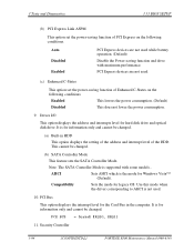
... of the HDD. Enabled This lowers the power consumption. (Default) Disabled This does not lower the power consumption. 9. AHCI Sets AHCI which is supported with maximum performance. PCI Bus This option displays the interrupt level for legacy OS. Note: The SATA Controller Mode is the mode for information only and cannot be changed. This cannot be changed . (b) SATA Controller Mode This feature sets the SATA Controller Mode. Security Controller 3-94 [CONFIDENTIAL] PORTEGE R500 Maintenance Manual (960-634) Drives I/O This option...
... of the HDD. Enabled This lowers the power consumption. (Default) Disabled This does not lower the power consumption. 9. AHCI Sets AHCI which is supported with maximum performance. PCI Bus This option displays the interrupt level for legacy OS. Note: The SATA Controller Mode is the mode for information only and cannot be changed. This cannot be changed . (b) SATA Controller Mode This feature sets the SATA Controller Mode. Security Controller 3-94 [CONFIDENTIAL] PORTEGE R500 Maintenance Manual (960-634) Drives I/O This option...
Maintenance Manual
Page 262
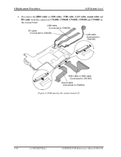
4 Replacement Procedures 4.18 System board 4. Disconnect the HDD cable (or SSD cable), USB cable, LAN cable, sound cable and BT cable from the connectors CN1800, CN9600, CN4100, CN9500 and CN4400 on the system board. USB cable (Connected to CN9600) BT cable (Connected to CN4400) LAN cable (Connected to CN4100) HDD cable or SSD cable (Connected to CN1800) Sound cable (Connected to CN9500) Figure 4-28 Removing the system board (2) 4-46 [CONFIDENTIAL] PORTÉGÉ R500 Maintenance Manual (960-634)
4 Replacement Procedures 4.18 System board 4. Disconnect the HDD cable (or SSD cable), USB cable, LAN cable, sound cable and BT cable from the connectors CN1800, CN9600, CN4100, CN9500 and CN4400 on the system board. USB cable (Connected to CN9600) BT cable (Connected to CN4400) LAN cable (Connected to CN4100) HDD cable or SSD cable (Connected to CN1800) Sound cable (Connected to CN9500) Figure 4-28 Removing the system board (2) 4-46 [CONFIDENTIAL] PORTÉGÉ R500 Maintenance Manual (960-634)


