User Guide
Page 14
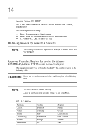
... is in the following table. 14 Approval Number: D01-1128JP TELECOM ENGINEERING CENTER Approval Number: 03NY.A0018, 03GZDA0017 The following restrictions apply: ❖ Do not disassemble or modify the device. ❖ Do not install the embedded wireless module into other device. ❖ 5.17 GHz to 5.23 GHz for indoor use only...
... is in the following table. 14 Approval Number: D01-1128JP TELECOM ENGINEERING CENTER Approval Number: 03NY.A0018, 03GZDA0017 The following restrictions apply: ❖ Do not disassemble or modify the device. ❖ Do not install the embedded wireless module into other device. ❖ 5.17 GHz to 5.23 GHz for indoor use only...
User Guide
Page 24
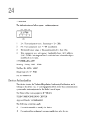
...4FH1 (4) 1 2.4: This equipment uses a frequency of 2.4 GHz. 2 FH: This equipment uses FH-SS modulation. 3 The interference range of mobile object identification systems. 3. 24 2. TOSHIBA Direct PC Monday - The Name of Japan. Indication The indication shown below appears on this equipment is impossible to 2,483.5 MHz. Friday: 10:00 - 17...Law of the radio equipment: EYXF2CS TELECOM ENGINEERING CENTER Approval Number: 01NYDA1305 The following restrictions apply: ❖ Do not disassemble or modify the device. ❖ Do not install the embedded wireless module into other device.
...4FH1 (4) 1 2.4: This equipment uses a frequency of 2.4 GHz. 2 FH: This equipment uses FH-SS modulation. 3 The interference range of mobile object identification systems. 3. 24 2. TOSHIBA Direct PC Monday - The Name of Japan. Indication The indication shown below appears on this equipment is impossible to 2,483.5 MHz. Friday: 10:00 - 17...Law of the radio equipment: EYXF2CS TELECOM ENGINEERING CENTER Approval Number: 01NYDA1305 The following restrictions apply: ❖ Do not disassemble or modify the device. ❖ Do not install the embedded wireless module into other device.
User Guide
Page 125
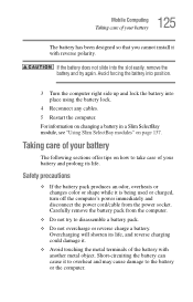
... forcing the battery into position. 3 Turn the computer right side up and lock the battery into the slot easily, remove the battery and try to disassemble a battery pack. ❖ Do not overcharge or reverse charge a battery. If the battery does not slide into place using the battery lock. 4 Reconnect any cables...
... forcing the battery into position. 3 Turn the computer right side up and lock the battery into the slot easily, remove the battery and try to disassemble a battery pack. ❖ Do not overcharge or reverse charge a battery. If the battery does not slide into place using the battery lock. 4 Reconnect any cables...
Maintenance Manual
Page 58
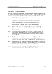
... the AC adaptor with a new one . Disassemble the computer following the steps described in Chapter 4, Replacement Procedures. If the AC adaptor still does not function properly, perform Check 2. Check 2 Replace the system board with a new one following the steps described in Chapter 4, Replacement Procedures. 2-16 PORTEGE M100 Maintenance Manual (960-452) Check the...
... the AC adaptor with a new one . Disassemble the computer following the steps described in Chapter 4, Replacement Procedures. If the AC adaptor still does not function properly, perform Check 2. Check 2 Replace the system board with a new one following the steps described in Chapter 4, Replacement Procedures. 2-16 PORTEGE M100 Maintenance Manual (960-452) Check the...
Maintenance Manual
Page 70
... 4, Replacement Procedures. 2-28 PORTEGE M100 Maintenance Manual (960-452) Check 2 The system board may be damaged. 2 Troubleshooting Procedures 2.4 System Board Troubleshooting Procedure 4 Replacement Check The system board connectors may be disconnected. Replace the system board with a new one following the steps described in Chapter 4, Replacement Procedures and perform Check 1. Disassemble the computer following...
... 4, Replacement Procedures. 2-28 PORTEGE M100 Maintenance Manual (960-452) Check 2 The system board may be damaged. 2 Troubleshooting Procedures 2.4 System Board Troubleshooting Procedure 4 Replacement Check The system board connectors may be disconnected. Replace the system board with a new one following the steps described in Chapter 4, Replacement Procedures and perform Check 1. Disassemble the computer following...
Maintenance Manual
Page 78
... repeat Procedure 1. Check 2 The HDD may be damaged. Disassemble the computer following the steps described in Chapter 4, Replacement Procedures. Replace it with a new one following the instructions in Chapter 4, Replacement Procedures and perform the following the instructions in Chapter 4, Replacement Procedures. 2-36 PORTEGE M100 Maintenance Manual (960-452) Check 3 The system board may...
... repeat Procedure 1. Check 2 The HDD may be damaged. Disassemble the computer following the steps described in Chapter 4, Replacement Procedures. Replace it with a new one following the instructions in Chapter 4, Replacement Procedures and perform the following the instructions in Chapter 4, Replacement Procedures. 2-36 PORTEGE M100 Maintenance Manual (960-452) Check 3 The system board may...
Maintenance Manual
Page 80
... a new one following checks: 1. If there is still an error, go to Check 4. Check 4 The PAD switch board or PAD switch cable may be damaged. Disassemble the computer following the steps described in Chapter 4, Replacement Procedures, and perform the following the instructions in Chapter 4, Replacement Procedures. 2-38 PORTEGE M100 Maintenance Manual (960-452)
... a new one following checks: 1. If there is still an error, go to Check 4. Check 4 The PAD switch board or PAD switch cable may be damaged. Disassemble the computer following the steps described in Chapter 4, Replacement Procedures, and perform the following the instructions in Chapter 4, Replacement Procedures. 2-38 PORTEGE M100 Maintenance Manual (960-452)
Maintenance Manual
Page 82
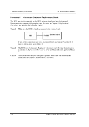
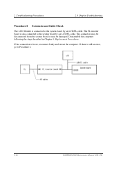
Disassemble the computer following the steps described in Chapter 4, Replacement Procedures. If there is loose, reconnect firmly and restart the computer. The FL inverter board is also connected to the system board by an LCD/FL cable. If the connection is still an error, go to Procedure 4. 2-40 PORTEGE M100 Maintenance Manual (960-452) The connectors may be disconnected from the system board or may be damaged. 2 Troubleshooting Procedures 2.8 Display Troubleshooting Procedure 3 Connector and Cable Check The LCD Module is connected to the system board by a n LCD/FL cable.
Disassemble the computer following the steps described in Chapter 4, Replacement Procedures. If there is loose, reconnect firmly and restart the computer. The FL inverter board is also connected to the system board by an LCD/FL cable. If the connection is still an error, go to Procedure 4. 2-40 PORTEGE M100 Maintenance Manual (960-452) The connectors may be disconnected from the system board or may be damaged. 2 Troubleshooting Procedures 2.8 Display Troubleshooting Procedure 3 Connector and Cable Check The LCD Module is connected to the system board by a n LCD/FL cable.
Maintenance Manual
Page 83
... connected to disassemble the computer and then perform the following the instructions in Chapter 4, Replacement Procedure and test the display again. If the problem still exists, perform Check2. Replace the FL/LCD or HV cable with a new one following the instructions in Chapter 4, Replacement Procedures and test the display again. PORTEGE M100 Maintenance...
... connected to disassemble the computer and then perform the following the instructions in Chapter 4, Replacement Procedure and test the display again. If the problem still exists, perform Check2. Replace the FL/LCD or HV cable with a new one following the instructions in Chapter 4, Replacement Procedures and test the display again. PORTEGE M100 Maintenance...
Maintenance Manual
Page 85
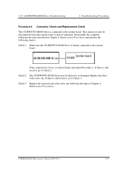
If the connection is connected to the system board. Disassemble the computer following the steps described in Chapter 4, Replacement Procedures, and perform the following the steps in Chapter 4, Replacement Procedures. Replace the drive with a new ... the system board. The connectors may be disconnected from the system board or may be damaged. If there is still an error, go to Check 2. PORTEGE M100 Maintenance Manual (960-452) 2-43 If there is still an error, go to Check 3. Check 2 The DVD-ROM drive may be defective or damaged...
If the connection is connected to the system board. Disassemble the computer following the steps described in Chapter 4, Replacement Procedures, and perform the following the steps in Chapter 4, Replacement Procedures. Replace the drive with a new ... the system board. The connectors may be disconnected from the system board or may be damaged. If there is still an error, go to Check 2. PORTEGE M100 Maintenance Manual (960-452) 2-43 If there is still an error, go to Check 3. Check 2 The DVD-ROM drive may be defective or damaged...
Maintenance Manual
Page 87
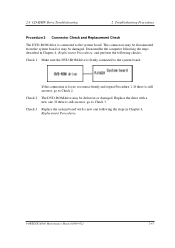
...an error, go to Check 2. If the connection is firmly connected to the system board. If there is still an error, go to Check 3. PORTEGE M100 Maintenance Manual (960-452) 2-45 Replace the drive with a new one . 2.10 CD-RW/DVD-ROM Drive Troubleshooting 2 Troubleshooting Procedures Procedure 2 Connector... CD-RW/DVD-ROM Drive is connected to the system board. The connectors may be disconnected from the system board or may be damaged. Disassemble the computer following checks: Check 1 Make sure the CD-RW/DVD-ROM Drive is loose, reconnect firmly and repeat Procedure 1. Check 3...
...an error, go to Check 2. If the connection is firmly connected to the system board. If there is still an error, go to Check 3. PORTEGE M100 Maintenance Manual (960-452) 2-45 Replace the drive with a new one . 2.10 CD-RW/DVD-ROM Drive Troubleshooting 2 Troubleshooting Procedures Procedure 2 Connector... CD-RW/DVD-ROM Drive is connected to the system board. The connectors may be disconnected from the system board or may be damaged. Disassemble the computer following checks: Check 1 Make sure the CD-RW/DVD-ROM Drive is loose, reconnect firmly and repeat Procedure 1. Check 3...
Maintenance Manual
Page 89
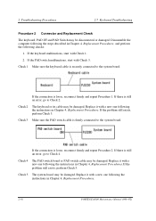
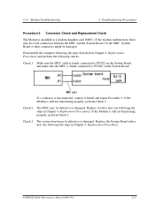
... the modem malfunctions, there may be a bad connection between the MDC and the System Board. Replace it firmly and repeat Procedure 1. PORTEGE M100 Maintenance Manual (960-452) 2-47 Replace the System Board with a new one following checks: Check 1 Make sure the MDC cable ... a new one following the steps in Chapter 4, Replacement Procedures. If a connector is firmly connected to PJ3020 on the System Board. Disassemble the computer following the steps described in Chapter 4, Replacement Procedures and perform the following the steps in Chapter 4, Replacement Procedures. Check ...
... the modem malfunctions, there may be a bad connection between the MDC and the System Board. Replace it firmly and repeat Procedure 1. PORTEGE M100 Maintenance Manual (960-452) 2-47 Replace the System Board with a new one following checks: Check 1 Make sure the MDC cable ... a new one following the steps in Chapter 4, Replacement Procedures. If a connector is firmly connected to PJ3020 on the System Board. Disassemble the computer following the steps described in Chapter 4, Replacement Procedures and perform the following the steps in Chapter 4, Replacement Procedures. Check ...
Maintenance Manual
Page 90
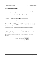
.... Perform the steps below starting with Procedure 1 and continuing with LAN cable is on the computer and run the test. Disassemble the computer following the steps described in Chapter 4, Replacement Procedures. 2-48 PORTEGE M100 Maintenance Manual (960-452) For the test, prepare a test Sound/LAN/Modem. Refer to Procedure 2. Procedure 1: Diagnostic Test Program...
.... Perform the steps below starting with Procedure 1 and continuing with LAN cable is on the computer and run the test. Disassemble the computer following the steps described in Chapter 4, Replacement Procedures. 2-48 PORTEGE M100 Maintenance Manual (960-452) For the test, prepare a test Sound/LAN/Modem. Refer to Procedure 2. Procedure 1: Diagnostic Test Program...
Maintenance Manual
Page 92
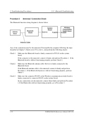
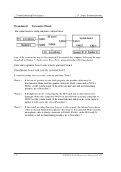
...is still not functioning properly, perform Check 3. In any connections are disconnected, connect them firmly and perform Procedure 1. Disassemble the computer following the steps described in Chapter 4, Replacement Procedures, and perform the following checks: Check 1 Make sure...If the Bluetooth function is disconnected, connect it firmly and perform Procedure 1. If the Bluetooth is firmly connected to Procedure 3. 2-50 PORTEGE M100 Maintenance Manual (960-452) If the Bluetooth board is shown below: Any of the connections may be disconnected. 2 Troubleshooting Procedures 2....
...is still not functioning properly, perform Check 3. In any connections are disconnected, connect them firmly and perform Procedure 1. Disassemble the computer following the steps described in Chapter 4, Replacement Procedures, and perform the following checks: Check 1 Make sure...If the Bluetooth function is disconnected, connect it firmly and perform Procedure 1. If the Bluetooth is firmly connected to Procedure 3. 2-50 PORTEGE M100 Maintenance Manual (960-452) If the Bluetooth board is shown below: Any of the connections may be disconnected. 2 Troubleshooting Procedures 2....
Maintenance Manual
Page 93
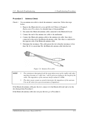
... 0.5-0.8Ω. 2. Figure 2-4 Antenna Test cable NOTE: 1. The above may not be stable with other is less than 5Ω, the Bluetooth antenna cable fails the test. PORTEGE M100 Maintenance Manual (960-452) 2-51 Refer to the end of the Bluetooth antenna cable. 5. The resistances determined with the steps above steps cannot accurately determine... an antenna test cable to Procedure 4. Follow the steps below: 1. Remove the Bluetooth slot cover and lift it to the multimeter. 4. Connect the end of disassembling. 2. If it is more than 5Ω.
... 0.5-0.8Ω. 2. Figure 2-4 Antenna Test cable NOTE: 1. The above may not be stable with other is less than 5Ω, the Bluetooth antenna cable fails the test. PORTEGE M100 Maintenance Manual (960-452) 2-51 Refer to the end of the Bluetooth antenna cable. 5. The resistances determined with the steps above steps cannot accurately determine... an antenna test cable to Procedure 4. Follow the steps below: 1. Remove the Bluetooth slot cover and lift it to the multimeter. 4. Connect the end of disassembling. 2. If it is more than 5Ω.
Maintenance Manual
Page 96
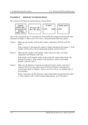
..., perform Check 2. If the wireless LAN function is shown below: Any of disassembling. In any connections are disconnected, connect them firmly and perform Procedure 1. Refer to Procedure 3. 2-54 PORTEGE M100 Maintenance Manual (960-452) Check 2 Make sure the wireless LAN antenna cables... on Wireless communication switch board. If the wireless LAN antenna cables are disconnected, connect them firmly and perform Procedure 1. Disassemble the computer following the steps described in Chapter 4, Replacement Procedures, and perform the following checks: Check 1 Make sure ...
..., perform Check 2. If the wireless LAN function is shown below: Any of disassembling. In any connections are disconnected, connect them firmly and perform Procedure 1. Refer to Procedure 3. 2-54 PORTEGE M100 Maintenance Manual (960-452) Check 2 Make sure the wireless LAN antenna cables... on Wireless communication switch board. If the wireless LAN antenna cables are disconnected, connect them firmly and perform Procedure 1. Disassemble the computer following the steps described in Chapter 4, Replacement Procedures, and perform the following checks: Check 1 Make sure ...
Maintenance Manual
Page 97
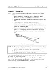
... an antenna test cable to the wireless LAN board. 3. If the wireless LAN antenna cables pass the test, connect them to the end of disassembling. 2. Refer to Procedure 4. PORTEGE M100 Maintenance Manual (960-452) 2-55 Follow the steps below: 1. One clip is about 0.5-0.8Ω. 2. If it off. Figure 2-5 Antenna Test cable NOTE: 1. The...
... an antenna test cable to the wireless LAN board. 3. If the wireless LAN antenna cables pass the test, connect them to the end of disassembling. 2. Refer to Procedure 4. PORTEGE M100 Maintenance Manual (960-452) 2-55 Follow the steps below: 1. One clip is about 0.5-0.8Ω. 2. If it off. Figure 2-5 Antenna Test cable NOTE: 1. The...
Maintenance Manual
Page 98
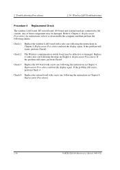
..., perform Check 4 Check 4 Replace the system board with a new one following the instructions in Chapter 4, Replacement Procedures. 2-56 PORTEGE M100 Maintenance Manual (960-452) Check 3 Replace the I /O board and system board are connected to disassemble the computer and then perform the following checks: Check 1 Replace the wireless LAN board with a new one following...
..., perform Check 4 Check 4 Replace the system board with a new one following the instructions in Chapter 4, Replacement Procedures. 2-56 PORTEGE M100 Maintenance Manual (960-452) Check 3 Replace the I /O board and system board are connected to disassemble the computer and then perform the following checks: Check 1 Replace the wireless LAN board with a new one following...
Maintenance Manual
Page 100
... not work correctly, perform Check 3. Make sure connector PJ9530 on the SD board is firmly connected to Procedure 3. 2-58 PORTEGE M100 Maintenance Manual (960-452) Go to PJ6000, PJ6001 on the SD board. Disassemble the computer following the steps described in Chapter 4, Replacement Procedures and perform the following checks: If the stereo speakers...
... not work correctly, perform Check 3. Make sure connector PJ9530 on the SD board is firmly connected to Procedure 3. 2-58 PORTEGE M100 Maintenance Manual (960-452) Go to PJ6000, PJ6001 on the SD board. Disassemble the computer following the steps described in Chapter 4, Replacement Procedures and perform the following checks: If the stereo speakers...
Maintenance Manual
Page 206
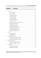
4 Replacement Procedures Chapter 4 Contents 4.1 General...4-1 Safety Precautions 4-2 Before You Begin 4-3 Disassembly Procedures 4-4 Assembly Procedures 4-4 Tools and Equipment 4-5 Screw Tightening Torque 4-6 Color of Screw Shaft 4-7 Marking of Screws on the Computer Body 4-7 Removing the Battery Pack 4-8 Installing ... Removing the Wireless LAN Card 4-18 Installing the Wireless LAN Card 4-21 4.5 RTC Battery...4-23 Removing the RTC Battery 4-24 Installing the RTC Battery 4-26 PORTEGE M100 Maintenance Manual (960-452) 4-iii
4 Replacement Procedures Chapter 4 Contents 4.1 General...4-1 Safety Precautions 4-2 Before You Begin 4-3 Disassembly Procedures 4-4 Assembly Procedures 4-4 Tools and Equipment 4-5 Screw Tightening Torque 4-6 Color of Screw Shaft 4-7 Marking of Screws on the Computer Body 4-7 Removing the Battery Pack 4-8 Installing ... Removing the Wireless LAN Card 4-18 Installing the Wireless LAN Card 4-21 4.5 RTC Battery...4-23 Removing the RTC Battery 4-24 Installing the RTC Battery 4-26 PORTEGE M100 Maintenance Manual (960-452) 4-iii


