
User Guide
Page 114
...cold. Leave the power connected and the battery should begin charging after a few minutes. The RTC battery powers the System Time Clock and BIOS Doing so may not start charging immediately under the following conditions: ❖ The battery is fully charged. A battery may reduce the ...RTC) battery. The battery needs to power the computer. Never leave batteries in the battery charger for more than a week at accessories.toshiba.com. To ensure that the battery charges to work with your notebook computer. 114 Mobile Computing Charging the batteries Charging the batteries NOTE ...
...cold. Leave the power connected and the battery should begin charging after a few minutes. The RTC battery powers the System Time Clock and BIOS Doing so may not start charging immediately under the following conditions: ❖ The battery is fully charged. A battery may reduce the ...RTC) battery. The battery needs to power the computer. Never leave batteries in the battery charger for more than a week at accessories.toshiba.com. To ensure that the battery charges to work with your notebook computer. 114 Mobile Computing Charging the batteries Charging the batteries NOTE ...

User Guide
Page 175
175 Toshiba Utilities TOSHIBA Console Select the boot device by pressing the right or left arrow keys, then pressing the Enter key. Allows you to one of "Dynamically Switchable," "... to configure the Fn function key emulation for the built-in LCD display and external video displays. ❖ CPU-Allows you to view the current BIOS. ❖ Device Config-Shows the Device configuration options.
175 Toshiba Utilities TOSHIBA Console Select the boot device by pressing the right or left arrow keys, then pressing the Enter key. Allows you to one of "Dynamically Switchable," "... to configure the Fn function key emulation for the built-in LCD display and external video displays. ❖ CPU-Allows you to view the current BIOS. ❖ Device Config-Shows the Device configuration options.
User Guide
Page 196
.... If you can occur. The operating system is easy. Resolving conflicts There are three things you install an older (legacy) device that helps the system BIOS (basic input/output system) and the operating system to automatically assign system resources to it from the computer. ❖ Disable another system component and use...
.... If you can occur. The operating system is easy. Resolving conflicts There are three things you install an older (legacy) device that helps the system BIOS (basic input/output system) and the operating system to automatically assign system resources to it from the computer. ❖ Disable another system component and use...

User Guide
Page 240
AC alternating current BIOS basic input/output system bps bits per second CD compact disc CD-ROM compact disc read-only memory CD-RW compact disc rewrite memory CMOS complementary metal-oxide semiconductor COM1 communications port 1 (serial port) COM2 communications port 2 (serial port) CPU central processing unit DC direct current 240 Acronyms The following acronyms may not be available on your computer. Glossary TECHNICAL NOTE: Some features defined in this glossary may appear in this user's guide.
AC alternating current BIOS basic input/output system bps bits per second CD compact disc CD-ROM compact disc read-only memory CD-RW compact disc rewrite memory CMOS complementary metal-oxide semiconductor COM1 communications port 1 (serial port) COM2 communications port 2 (serial port) CPU central processing unit DC direct current 240 Acronyms The following acronyms may not be available on your computer. Glossary TECHNICAL NOTE: Some features defined in this glossary may appear in this user's guide.
User Guide
Page 243
...in which the central processing unit (CPU) communicates with other parts of signal changes per second). boot disk - basic input/output system (BIOS) - It is the pathway through which information is the smallest unit of information used in the diskette drive before checking the hard disk..., the computer looks for "binary digit." A computer program that you start the computer. Baud rate is similar, but not identical, to another. BIOS (basic input/output system) - bit: - See also byte. See also baud rate. The term "boot" originates from one device to the baud...
...in which the central processing unit (CPU) communicates with other parts of signal changes per second). boot disk - basic input/output system (BIOS) - It is the pathway through which information is the smallest unit of information used in the diskette drive before checking the hard disk..., the computer looks for "binary digit." A computer program that you start the computer. Baud rate is similar, but not identical, to another. BIOS (basic input/output system) - bit: - See also byte. See also baud rate. The term "boot" originates from one device to the baud...

User Guide
Page 252
... read. To reset the computer by a printer or displayed on most U.S. ROM (read -only memory - This type of memory is used to store your computer's BIOS, which is receiving power. By volatile, we mean that can be produced by reloading the operating system without turning the computer off your computer's main... the file's type, size, and creation date. See also memory. reboot - A disk that can be removed from a disk drive. For a screen, it up. See also BIOS, memory.
... read. To reset the computer by a printer or displayed on most U.S. ROM (read -only memory - This type of memory is used to store your computer's BIOS, which is receiving power. By volatile, we mean that can be produced by reloading the operating system without turning the computer off your computer's main... the file's type, size, and creation date. See also memory. reboot - A disk that can be removed from a disk drive. For a screen, it up. See also BIOS, memory.
Maintenance Manual
Page 4
... and Diagnostics describes how to perform test and diagnostic operations for maintenance service. Appendices The appendices describe the following parts: Chapter 1 Hardware Overview describes the PORTEGE M100 system unit and each FRU. Chapter 4 Replacement Procedures describes the removal and replacement of the FRUs. The manual is divided into the following : q Handling the...
... and Diagnostics describes how to perform test and diagnostic operations for maintenance service. Appendices The appendices describe the following parts: Chapter 1 Hardware Overview describes the PORTEGE M100 system unit and each FRU. Chapter 4 Replacement Procedures describes the removal and replacement of the FRUs. The manual is divided into the following : q Handling the...

Maintenance Manual
Page 10
Appendices Appendix A Appendix B Appendix C Appendix D Appendix E Appendix F Appendix G Appendix H Appendix I Handling the LCD Module A-1 Board Layout B-1 Pin Assignments C-1 Keyboard Scan/Character Codes D-1 Key Layout ...E-1 Wiring Diagrams F-1 BIOS Rewrite Procedures G-1 EC/KBC Rewrite Procedures H-1 Reliability...I-1 x PORTEGE M100 Maintenance Manual (960 -452)
Appendices Appendix A Appendix B Appendix C Appendix D Appendix E Appendix F Appendix G Appendix H Appendix I Handling the LCD Module A-1 Board Layout B-1 Pin Assignments C-1 Keyboard Scan/Character Codes D-1 Key Layout ...E-1 Wiring Diagrams F-1 BIOS Rewrite Procedures G-1 EC/KBC Rewrite Procedures H-1 Reliability...I-1 x PORTEGE M100 Maintenance Manual (960 -452)

Maintenance Manual
Page 22
... 1.20V - Bus master IDE Controller (Ultra ATA 100/66/33) - SM Bus 2.0 controller - FWH Interface (BIOS) - IRQ controller - Serial Interrupt function - Hub Link Interface - Power Management function - Internal RTC - 421-ball (31mm×31mm) BGA Package PORTEGE M100 Maintenance Manual (960 -452) 1-7 Integrated L1 cache memory: 64KB - Supports Deeper Sleep (4). - Suspend/Resume control...
... 1.20V - Bus master IDE Controller (Ultra ATA 100/66/33) - SM Bus 2.0 controller - FWH Interface (BIOS) - IRQ controller - Serial Interrupt function - Hub Link Interface - Power Management function - Internal RTC - 421-ball (31mm×31mm) BGA Package PORTEGE M100 Maintenance Manual (960 -452) 1-7 Integrated L1 cache memory: 64KB - Supports Deeper Sleep (4). - Suspend/Resume control...

Maintenance Manual
Page 60
...error message is displayed, perform Check 2. (a)*** Bad time function *** Check system. These errors occur, when the system configuration preserved in the BIOS ROM. 2 Troubleshooting Procedures 2.4 System Board Troubleshooting Procedure 1 Message Check When the power is lost. The IRT tests each IC on the ...q If nothing is displayed, go to Procedure 2. q If an operating system is inconsistent*** Check system. Then press [F1] key 2-18 PORTEGE M100 Maintenance Manual (960-452) If you press the F1 key as the message instructs. Then press [F1] key (c)*** RTC battery is low...
...error message is displayed, perform Check 2. (a)*** Bad time function *** Check system. These errors occur, when the system configuration preserved in the BIOS ROM. 2 Troubleshooting Procedures 2.4 System Board Troubleshooting Procedure 1 Message Check When the power is lost. The IRT tests each IC on the ...q If nothing is displayed, go to Procedure 2. q If an operating system is inconsistent*** Check system. Then press [F1] key 2-18 PORTEGE M100 Maintenance Manual (960-452) If you press the F1 key as the message instructs. Then press [F1] key (c)*** RTC battery is low...

Maintenance Manual
Page 63
...the LED status from binary to IRT BIOS rewrite register initialization PIT channel 1 initialization PIT, DMAC,PIC initialization Memory type check Cache bus, L2 initialization, configuration Enabling L1 cache Memory clear Protecting flash ROM area cache PORTEGE M100 Maintenance Manual (960-452) 2-21...item Start Flash ROM check B1h EC/KBC rewrite check B2h BIOS rewrite System BIOS rewrite transition to IRT BIOS rewrite process B5h Message Register initialization for boot block PIT ch.0 initialization BIOS rewrite flag initialization Transition to protected mode Boot block checksum ...
...the LED status from binary to IRT BIOS rewrite register initialization PIT channel 1 initialization PIT, DMAC,PIC initialization Memory type check Cache bus, L2 initialization, configuration Enabling L1 cache Memory clear Protecting flash ROM area cache PORTEGE M100 Maintenance Manual (960-452) 2-21...item Start Flash ROM check B1h EC/KBC rewrite check B2h BIOS rewrite System BIOS rewrite transition to IRT BIOS rewrite process B5h Message Register initialization for boot block PIT ch.0 initialization BIOS rewrite flag initialization Transition to protected mode Boot block checksum ...

Maintenance Manual
Page 65
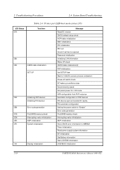
2.4 System Board Troubleshooting 2 Troubleshooting Procedures Table 2-4 Printer port LED boot mode status (2/5) LED Status B7h Test item BIOS rewriting check 00h IRT Check system 01h Memory check SM-RAM stack area test 02h CMOS check and initialization 03h Resume branch ...clear System BIOS RAM area checksum System BIOS ROM to RAM copy SMRAM initialization Wake Up check SMRAM base rewrite and BIOS CPU state map store Set SMI handler to runtime Rewriting of SRAM base Storage of CPU s tate map Setting of device necessary before initializing of PCI bus PORTEGE M100 Maintenance Manual ...
2.4 System Board Troubleshooting 2 Troubleshooting Procedures Table 2-4 Printer port LED boot mode status (2/5) LED Status B7h Test item BIOS rewriting check 00h IRT Check system 01h Memory check SM-RAM stack area test 02h CMOS check and initialization 03h Resume branch ...clear System BIOS RAM area checksum System BIOS ROM to RAM copy SMRAM initialization Wake Up check SMRAM base rewrite and BIOS CPU state map store Set SMI handler to runtime Rewriting of SRAM base Storage of CPU s tate map Setting of device necessary before initializing of PCI bus PORTEGE M100 Maintenance Manual ...
Maintenance Manual
Page 66
... NDP initialization Store CMOS error information to SMRAM Timer initialization Read power supply system information EC initialization Get Battery information Get LCD EDID information VGA BIOS initialization 2-24 PORTEGE M100 Maintenance Manual (960-452)
... NDP initialization Store CMOS error information to SMRAM Timer initialization Read power supply system information EC initialization Get Battery information Get LCD EDID information VGA BIOS initialization 2-24 PORTEGE M100 Maintenance Manual (960-452)

Maintenance Manual
Page 68
... update INT 15h E820h function memory map rewrite DMI wake up update and SM-BIOS structure table update ACPI table update MMI mask release Wait for PSC version writing on BIOS TIT checksum Runtime IRT flag clear Runtime checksum update Hibernation branch CPU, HDD upgrade... check Set battery save mode Set date Close PCI device configuration area Cache control Wait for serial port initialization completion Runtime checksum update Set thermal duty 2-26 PORTEGE M100 Maintenance Manual...
... update INT 15h E820h function memory map rewrite DMI wake up update and SM-BIOS structure table update ACPI table update MMI mask release Wait for PSC version writing on BIOS TIT checksum Runtime IRT flag clear Runtime checksum update Hibernation branch CPU, HDD upgrade... check Set battery save mode Set date Close PCI device configuration area Cache control Wait for serial port initialization completion Runtime checksum update Set thermal duty 2-26 PORTEGE M100 Maintenance Manual...

Maintenance Manual
Page 116
...UUID Number : XXXXXXXXXXXXXXXXXXXXXXXXXXXXXXXX Press [Enter] to EXIT To exit this subtest and return to the subtest you press Enter, the fan should stop. PORTEGE M100 Maintenance Manual (960-452) 3-9 When you want to FFFFFh, 64KB) on the System Board. Subtest 07 DMI read This subtest displays the ...executes a checksum test of the fan starts and press Enter. *** Fan OFF *** : Press [Enter] key? Make sure the rotation of the BIOS ROM (range: F0000h to execute and press Enter. The following message will appear. Make sure the rotation of the fan stops and press Enter. ...
...UUID Number : XXXXXXXXXXXXXXXXXXXXXXXXXXXXXXXX Press [Enter] to EXIT To exit this subtest and return to the subtest you press Enter, the fan should stop. PORTEGE M100 Maintenance Manual (960-452) 3-9 When you want to FFFFFh, 64KB) on the System Board. Subtest 07 DMI read This subtest displays the ...executes a checksum test of the fan starts and press Enter. *** Fan OFF *** : Press [Enter] key? Make sure the rotation of the BIOS ROM (range: F0000h to execute and press Enter. The following message will appear. Make sure the rotation of the fan stops and press Enter. ...

Maintenance Manual
Page 118
... Test 3 Tests and Diagnostics Subtest 10 Subtest 11 Subtest 12 Subtest 13 Temperature surveillance test Settings at the start of test • BIOS test mode (FAN -forced high speed, prohibition of SM interruptionetc.) • Prohibition of TCC throttling (Tj = 100C) • ... temperature of the temperature is different in each system, so use data informed by the system department. Battery Data * Battery Type = XXXXXXXXXXXX PORTEGE M100 Maintenance Manual (960-452) 3-11 Battery Data * Battery Type = XXXXXXXXXXXX Option Battery F/W test This subtest reads F/W data from the battery...
... Test 3 Tests and Diagnostics Subtest 10 Subtest 11 Subtest 12 Subtest 13 Temperature surveillance test Settings at the start of test • BIOS test mode (FAN -forced high speed, prohibition of SM interruptionetc.) • Prohibition of TCC throttling (Tj = 100C) • ... temperature of the temperature is different in each system, so use data informed by the system department. Battery Data * Battery Type = XXXXXXXXXXXX PORTEGE M100 Maintenance Manual (960-452) 3-11 Battery Data * Battery Type = XXXXXXXXXXXX Option Battery F/W test This subtest reads F/W data from the battery...
Maintenance Manual
Page 141
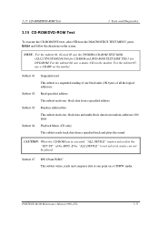
... from a specified track and plays the sound. Subtest 01 Subtest 02 Subtest 03 Subtest 04 Sequential read This subtest is a sequential reading of the BIOS. Random address/data This subtest reads one -block data from random addresses 200 times. Read specified address This subtest reads one -block data and multi... on a CD/RW media. If the "ALL DEVICE" is selected in the "SET-UP" of one point on the screen. PORTEGE M100 Maintenance Manual (960-452) 3-33 For the subtest 04, use the TOSHIBA CD-ROM TEST DISK (ZA1217P01/P000204190) for CD-ROM and DVD-ROM TEST DISK TSD-1 for DVD-ROM.
... from a specified track and plays the sound. Subtest 01 Subtest 02 Subtest 03 Subtest 04 Sequential read This subtest is a sequential reading of the BIOS. Random address/data This subtest reads one -block data from random addresses 200 times. Read specified address This subtest reads one -block data and multi... on a CD/RW media. If the "ALL DEVICE" is selected in the "SET-UP" of one point on the screen. PORTEGE M100 Maintenance Manual (960-452) 3-33 For the subtest 04, use the TOSHIBA CD-ROM TEST DISK (ZA1217P01/P000204190) for CD-ROM and DVD-ROM TEST DISK TSD-1 for DVD-ROM.

Maintenance Manual
Page 157
MS-DOS Version 4. Sound System 11. The number of HWSC 19. The number of hard disk drives 18. Date/Time 3-48 PORTEGE M100 Maintenance Manual (960-452) Boot ROM version 6. Battery code 10. The number of math co-processors 14. The number of ASYNC ports 13. KBC version 7. ...Total Memory Size 9. The number of printer ports 12. BIOS ROM version (1st ID, 2nd ID) 5. PS Microprocessor Version (EC Version) 8. The number of Bluetooth 21. The number of IEEE1394 22. The number of ...
MS-DOS Version 4. Sound System 11. The number of HWSC 19. The number of hard disk drives 18. Date/Time 3-48 PORTEGE M100 Maintenance Manual (960-452) Boot ROM version 6. Battery code 10. The number of math co-processors 14. The number of ASYNC ports 13. KBC version 7. ...Total Memory Size 9. The number of printer ports 12. BIOS ROM version (1st ID, 2nd ID) 5. PS Microprocessor Version (EC Version) 8. The number of Bluetooth 21. The number of IEEE1394 22. The number of ...
Maintenance Manual
Page 158
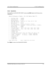
... * - X Math CO-Processor * - X IEEE1394 * - X ASYNC Adapter COM1 = 03F8 COM2 = XXXX COM3 = XXXX * - X Floppy Disk Drive(s) Track = XX Head = XX, Sector = XX * - PORTEGE M100 Maintenance Manual (960-452) 3-49 VGA Controller = XXXXXX * - BIOS ROM Version = VX.XX 1st ID = XXH, 2nd ID = XXH * - MS-DOS Version = V7.XX * - X Bluetooth * - X PCMCIA Slot * - X USB2.0 FIR Press...
... * - X Math CO-Processor * - X IEEE1394 * - X ASYNC Adapter COM1 = 03F8 COM2 = XXXX COM3 = XXXX * - X Floppy Disk Drive(s) Track = XX Head = XX, Sector = XX * - PORTEGE M100 Maintenance Manual (960-452) 3-49 VGA Controller = XXXXXX * - BIOS ROM Version = VX.XX 1st ID = XXH, 2nd ID = XXH * - MS-DOS Version = V7.XX * - X Bluetooth * - X PCMCIA Slot * - X USB2.0 FIR Press...

Maintenance Manual
Page 162
...3 Tests and Diagnostics 3.23.2 Accessing the SETUP Program Selecting 0 from the DIAGNOSTICS MENU and pressing Enter displays the SETUP screen. SYSTEM SETUP (1/2) ACPI BIOS version = X.XX MEMORY Total = XXXXX KB SYSTEM DATE/TIME Date(MM-DD-YY) = XX-XX-XXXX Time(HH:MM:SS) = XX:XX...→CD-ROM→LAN HDD Priority = Built -in Resume mode. Others Power-up Mode is divided into two pages. PORTEGE M100 Maintenance Manual (960-452) 3-53 SYSTEM SETUP (2/2) ACPI BIOS version = X.XX = Setup by OS PC CARD Controller Mode = Auto-Selected I/O PORTS Serial = COM1(3F8H/IRQ4) Parallel...
...3 Tests and Diagnostics 3.23.2 Accessing the SETUP Program Selecting 0 from the DIAGNOSTICS MENU and pressing Enter displays the SETUP screen. SYSTEM SETUP (1/2) ACPI BIOS version = X.XX MEMORY Total = XXXXX KB SYSTEM DATE/TIME Date(MM-DD-YY) = XX-XX-XXXX Time(HH:MM:SS) = XX:XX...→CD-ROM→LAN HDD Priority = Built -in Resume mode. Others Power-up Mode is divided into two pages. PORTEGE M100 Maintenance Manual (960-452) 3-53 SYSTEM SETUP (2/2) ACPI BIOS version = X.XX = Setup by OS PC CARD Controller Mode = Auto-Selected I/O PORTS Serial = COM1(3F8H/IRQ4) Parallel...


