
User Guide
Page 3
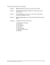
... and diagnostic operations for maintenance service. The manual is divided into the following : u Handling the LCD module u Board layout u Pin assignments u Key layout u Wiring diagrams u BIOS Rewrite Procedures u Reliability Libretto 50CT/70CT Maintenance Manual iii Appendices The appendices describe the following parts: Chapter 1 Hardware Overview describes the system unit and each FRU.
... and diagnostic operations for maintenance service. The manual is divided into the following : u Handling the LCD module u Board layout u Pin assignments u Key layout u Wiring diagrams u BIOS Rewrite Procedures u Reliability Libretto 50CT/70CT Maintenance Manual iii Appendices The appendices describe the following parts: Chapter 1 Hardware Overview describes the system unit and each FRU.
User Guide
Page 7
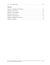
4.16 I/O Adapter Board 4-33 Appendices Appendix A Handling the LCD Module A-1 Appendix B Board Layout B-1 Appendix C Pin Assignments C-1 Appendix D Key Layouts D-1 Appendix E Wiring Diagrams E-1 Appendix F BIOS Rewrite Procedures F-1 Appendix G Reliability...G-1 Libretto 50CT/70CT Maintenance Manual vii
4.16 I/O Adapter Board 4-33 Appendices Appendix A Handling the LCD Module A-1 Appendix B Board Layout B-1 Appendix C Pin Assignments C-1 Appendix D Key Layouts D-1 Appendix E Wiring Diagrams E-1 Appendix F BIOS Rewrite Procedures F-1 Appendix G Reliability...G-1 Libretto 50CT/70CT Maintenance Manual vii

User Guide
Page 18
... (Flash EEPROM) • 256 KB, one 256K x 8-bit chip − 64 KB are used for system BIOS − 40 KB are used for VGA BIOS − 152 KB are reserved • Access time 120 ns • Data transfer is 8-bit width q Expansion memory One expansion memory slot is used. 1 Hardware ...: Intel 75 MHz Pentium processor operates at 2.9/3.3 volts and incorporates the math co-processor and 16 KB cache memory. ∗Libretto 70CT: Intel 120 MHz Pentium processor with MMX technology operates at 2.9/3.3 volts and incorporates the math co-processor and 16 KB cache memory. q Video RAM • 1 ...
... (Flash EEPROM) • 256 KB, one 256K x 8-bit chip − 64 KB are used for system BIOS − 40 KB are used for VGA BIOS − 152 KB are reserved • Access time 120 ns • Data transfer is 8-bit width q Expansion memory One expansion memory slot is used. 1 Hardware ...: Intel 75 MHz Pentium processor operates at 2.9/3.3 volts and incorporates the math co-processor and 16 KB cache memory. ∗Libretto 70CT: Intel 120 MHz Pentium processor with MMX technology operates at 2.9/3.3 volts and incorporates the math co-processor and 16 KB cache memory. q Video RAM • 1 ...
User Guide
Page 19
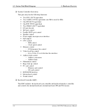
and controls: the internal keyboard, external keyboard, IPS and PS/2 mouse. 1-6 Libretto 50CT/70CT Maintenance Manual 1.2 System Unit Block Diagram 1 Hardware Overview q System Controller Gate Array This gate array has the following functions: • Two PICs... latch • Hibernation control • Ring wake up control • PC card control − Memory card control − I/O card control • BIOS-ROM interface • Infrared port control • Sound control q Keyboard Controller (KBC) This KBC includes: the keyboard scan controller and keyboard interface controller;
and controls: the internal keyboard, external keyboard, IPS and PS/2 mouse. 1-6 Libretto 50CT/70CT Maintenance Manual 1.2 System Unit Block Diagram 1 Hardware Overview q System Controller Gate Array This gate array has the following functions: • Two PICs... latch • Hibernation control • Ring wake up control • PC card control − Memory card control − I/O card control • BIOS-ROM interface • Infrared port control • Sound control q Keyboard Controller (KBC) This KBC includes: the keyboard scan controller and keyboard interface controller;

User Guide
Page 27
.... 5. Controls power on/off. 6. Table 1-6 Power supply board output rating Use CPU, RAM, GA, VGA, VRAM GA, BIOS ROM, KBC, PC card Name B3V VCC DC voltage (V) +3.3 +12.0 Regulation tolerance (%) ±5 ±5 1-14 Libretto 50CT/70CT Maintenance Manual Detects DC output and circuit malfunctions. 3. Provides more accurate detection of voltages to the computer...
.... 5. Controls power on/off. 6. Table 1-6 Power supply board output rating Use CPU, RAM, GA, VGA, VRAM GA, BIOS ROM, KBC, PC card Name B3V VCC DC voltage (V) +3.3 +12.0 Regulation tolerance (%) ±5 ±5 1-14 Libretto 50CT/70CT Maintenance Manual Detects DC output and circuit malfunctions. 3. Provides more accurate detection of voltages to the computer...

User Guide
Page 43
... error message is properly loaded, go to set the system configuration. q If Toshiba MS-DOS or Toshiba Windows 95 is shown on the system board and initializes it. If any other... RTC battery *** Check system. Then press [F1] key ...... (c) *** Bad configuration *** Check system. Then press [F1] key ...... 2-10 Libretto 50CT/70CT Maintenance Manual If error message (b) displays often when the power is on , the system performs the Initial Reliability Test (IRT) installed in Hibernation Mode... Printer Port LED Check in Boot Mode Procedure 3: Printer Port LED Check in the BIOS ROM.
... error message is properly loaded, go to set the system configuration. q If Toshiba MS-DOS or Toshiba Windows 95 is shown on the system board and initializes it. If any other... RTC battery *** Check system. Then press [F1] key ...... (c) *** Bad configuration *** Check system. Then press [F1] key ...... 2-10 Libretto 50CT/70CT Maintenance Manual If error message (b) displays often when the power is on , the system performs the Initial Reliability Test (IRT) installed in Hibernation Mode... Printer Port LED Check in Boot Mode Procedure 3: Printer Port LED Check in the BIOS ROM.

User Guide
Page 48
... Procedure 5. Convert the status from left to right as you face the back of status System BIOS RAM checksum error Optional ROM or Optional Card (CGA,MDA) is in Table 2-4, go to hexadecimal notation. 6. Libretto 50CT/70CT Maintenance Manual 2-15 Plug the printer port LED into the computer's parallel port. 3. If the final...
... Procedure 5. Convert the status from left to right as you face the back of status System BIOS RAM checksum error Optional ROM or Optional Card (CGA,MDA) is in Table 2-4, go to hexadecimal notation. 6. Libretto 50CT/70CT Maintenance Manual 2-15 Plug the printer port LED into the computer's parallel port. 3. If the final...

User Guide
Page 74
3 Tests and Diagnostics 3.4 System Test 3.4 System Test To execute the System Test select 1 from the Diagnostic Test Menu, press Enter and follow the directions on the system board. Move the highlight bar to the subtest you want to execute and press Enter. Libretto 50CT/70CT Maintenance Manual 3-9 Subtest 01 ROM checksum This subtest executes a checksum test of the BIOS ROM on the screen. The System Test contains one test that tests the system.
3 Tests and Diagnostics 3.4 System Test 3.4 System Test To execute the System Test select 1 from the Diagnostic Test Menu, press Enter and follow the directions on the system board. Move the highlight bar to the subtest you want to execute and press Enter. Libretto 50CT/70CT Maintenance Manual 3-9 Subtest 01 ROM checksum This subtest executes a checksum test of the BIOS ROM on the screen. The System Test contains one test that tests the system.

User Guide
Page 114
... clock 3.23.2 Operations Select 8 from the Diagnostic Menu and press Enter to the Diagnostic Menu. KBC version 4. BIOS ROM VERSION = VX.XX - Boot ROM version 3. System memory size 6. KBC VERSION = VX.XX - Number of hard disk drives 9. Libretto 50CT/70CT Maintenance Manual 3-49 Extended memory size 11. Number of math co-processors 12...
... clock 3.23.2 Operations Select 8 from the Diagnostic Menu and press Enter to the Diagnostic Menu. KBC version 4. BIOS ROM VERSION = VX.XX - Boot ROM version 3. System memory size 6. KBC VERSION = VX.XX - Number of hard disk drives 9. Libretto 50CT/70CT Maintenance Manual 3-49 Extended memory size 11. Number of math co-processors 12...

User Guide
Page 115
...Off (d) Alarm Volume (e) System Beep (f) Panel Power On/Off (g) Alarm Power On (h) Pointing Devices (i) Boot Priority 3-50 Libretto 50CT/70CT Maintenance Manual Password 5. Display (a) Display Adapter (b) LCD Display Colors (c) Power On Display (d) VGA Segment Address (e) Text Mode Stretch 3. Memory... (a) Total (b) Base (c) Extended (d) Shadow BIOS ROM 2. I/O Ports (a) Serial Port (b) Infared Port (c) Parallel Port (d) ...
...Off (d) Alarm Volume (e) System Beep (f) Panel Power On/Off (g) Alarm Power On (h) Pointing Devices (i) Boot Priority 3-50 Libretto 50CT/70CT Maintenance Manual Password 5. Display (a) Display Adapter (b) LCD Display Colors (c) Power On Display (d) VGA Segment Address (e) Text Mode Stretch 3. Memory... (a) Total (b) Base (c) Extended (d) Shadow BIOS ROM 2. I/O Ports (a) Serial Port (b) Infared Port (c) Parallel Port (d) ...

User Guide
Page 118
... computer. (c) Extended Displays the amount of memory beyond base memory that the computer can access. (d) Shadow BIOS ROM Displays 256 KB, the amount of memory installed and is divided into functionally related groups. Libretto 50CT/70CT Maintenance Manual 3-53 You cannot change these values. (a) Total Displays the total amount of RAM used to...
... computer. (c) Extended Displays the amount of memory beyond base memory that the computer can access. (d) Shadow BIOS ROM Displays 256 KB, the amount of memory installed and is divided into functionally related groups. Libretto 50CT/70CT Maintenance Manual 3-53 You cannot change these values. (a) Total Displays the total amount of RAM used to...

User Guide
Page 169
... Connector E-1 E.3 Serial Port Direct Cable (9-Pin to 9-Pin E-2 E.4 Serial Port Direct Cable (9-Pin to 25-Pin E-2 Appendix F BIOS Rewrite Procedures F-1 Appendix G Reliability...G-1 Figures Figure B-1 System board layout (front B-1 Figure B-2 System board layout (back B-2 Libretto 50CT/70CT Maintenance Manual App-iii Table of Contents Appendix A Handling the LCD Module A-1 Appendix B Board Layout B-1 B.1 System Board...
... Connector E-1 E.3 Serial Port Direct Cable (9-Pin to 9-Pin E-2 E.4 Serial Port Direct Cable (9-Pin to 25-Pin E-2 Appendix F BIOS Rewrite Procedures F-1 Appendix G Reliability...G-1 Figures Figure B-1 System board layout (front B-1 Figure B-2 System board layout (back B-2 Libretto 50CT/70CT Maintenance Manual App-iii Table of Contents Appendix A Handling the LCD Module A-1 Appendix B Board Layout B-1 B.1 System Board...

User Guide
Page 193
Turn the power off. 3. Libretto 50CT/70CT Maintenance Manual F-1 Appendix F Appendix F BIOS Rewrite Procedures This Appendix explains how to rewrite the system BIOS program to start the BIOS rewrite program. 6. Remove the external cable and any optional memory or PC card. 4. When the BIOS message displays, insert the diagnostics disk into... is completed, eject the diagnostics disk and press the reset switch to boot mode. 2. Turn the power on the Libretto 50CT/70CT/70CT. Tools To rewrite the BIOS, you need the following tool: q Diagnostics disk for the computer Rewriting the...
Turn the power off. 3. Libretto 50CT/70CT Maintenance Manual F-1 Appendix F Appendix F BIOS Rewrite Procedures This Appendix explains how to rewrite the system BIOS program to start the BIOS rewrite program. 6. Remove the external cable and any optional memory or PC card. 4. When the BIOS message displays, insert the diagnostics disk into... is completed, eject the diagnostics disk and press the reset switch to boot mode. 2. Turn the power on the Libretto 50CT/70CT/70CT. Tools To rewrite the BIOS, you need the following tool: q Diagnostics disk for the computer Rewriting the...


