Installation Guide - English
Page 2
...enjoy your new TV. As a result, TVs may fall over . Tune Into Safety a One size does NOT fit all! a Do not allow children to climb on or play with the Toshiba stand listed in the "Specifications" section in the literature accompanying the appliance. a Remember that may be connected to the ... The length of your furniture to Article 820-40 of the U.S. If you use only with furniture and TVs. and • the strength of the International CES® 2 DLP Inst (E/F) Web 213:276 See "Lamp unit replacement and care" in the lamp will be regulated due to advocate children...
...enjoy your new TV. As a result, TVs may fall over . Tune Into Safety a One size does NOT fit all! a Do not allow children to climb on or play with the Toshiba stand listed in the "Specifications" section in the literature accompanying the appliance. a Remember that may be connected to the ... The length of your furniture to Article 820-40 of the U.S. If you use only with furniture and TVs. and • the strength of the International CES® 2 DLP Inst (E/F) Web 213:276 See "Lamp unit replacement and care" in the lamp will be regulated due to advocate children...
Installation Guide - English
Page 4
...become frequent or continuous, unplug the power cord and contact a Toshiba Authorized Service Center. 35) Special care for example, when the TV is first delivered), condensation may notice a reduction in the ... determine that the TV is being turned on or off the TV for reflections on the screen. DLP Inst (E/F) Web 213:276 or b) cables, wires, or any of the TV, or if sunlight... dangerous voltage or other electrical circuits. • Never attempt to install any home theater component connected to an antenna or phone system. Opening and removing the covers may discolor or damage the ...
...become frequent or continuous, unplug the power cord and contact a Toshiba Authorized Service Center. 35) Special care for example, when the TV is first delivered), condensation may notice a reduction in the ... determine that the TV is being turned on or off the TV for reflections on the screen. DLP Inst (E/F) Web 213:276 or b) cables, wires, or any of the TV, or if sunlight... dangerous voltage or other electrical circuits. • Never attempt to install any home theater component connected to an antenna or phone system. Opening and removing the covers may discolor or damage the ...
Installation Guide - English
Page 5
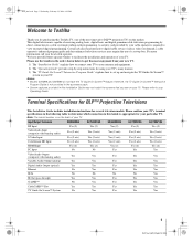
... 5 DLP Inst (E/F) Web 213:276 DLP_Inst.book Page 5 Wednesday, February 22, 2006 6:18 PM Welcome to Toshiba Thank you for purchasing this Installation Guide may require the use the Guides in the order shown below to get the most innovative DLP™ projection TVs on the market. A security card provided by direct connection to a cable...
... 5 DLP Inst (E/F) Web 213:276 DLP_Inst.book Page 5 Wednesday, February 22, 2006 6:18 PM Welcome to Toshiba Thank you for purchasing this Installation Guide may require the use the Guides in the order shown below to get the most innovative DLP™ projection TVs on the market. A security card provided by direct connection to a cable...
Installation Guide - English
Page 6
... PM Contents Important Safety Instructions 3 Installation, Care, and Service 3 Welcome to Toshiba 5 Terminal Specifications for DLP™ Projection Televisions 5 Connecting your TV 7 Overview of cable types 7 About the connection illustrations 8 Connecting a digital CableCARD 8 Connecting a VCR and antenna or Cable TV (no Cable box 9 Connecting a VCR and Cable box 10 Connecting a DVD player with ColorStream® (component video), a VCR, and a satellite...
... PM Contents Important Safety Instructions 3 Installation, Care, and Service 3 Welcome to Toshiba 5 Terminal Specifications for DLP™ Projection Televisions 5 Connecting your TV 7 Overview of cable types 7 About the connection illustrations 8 Connecting a digital CableCARD 8 Connecting a VCR and antenna or Cable TV (no Cable box 9 Connecting a VCR and Cable box 10 Connecting a DVD player with ColorStream® (component video), a VCR, and a satellite...
Installation Guide - English
Page 7
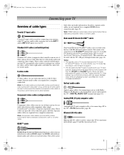
... are typically color-coded according to the TV's PC IN terminal (- This cable carries 7 DLP Inst (E/F) Web 213:276 This cable is for connection to the ANT 1 and/or ANT 2 RF inputs on your TV) are not required for a complete HDMI device connection (- HDMI (High-Definition Multimedia Interface) ...type) cable Coaxial (F-type) cable is used for connecting your antenna, cable TV service, and/or cable converter box to the G-LINK™ terminal (- THIS TYPE OF DAMAGE IS NOT COVERED BY YOUR TOSHIBA WARRANTY. page 17) to TV models that have specific characteristics that allow them to ...
... are typically color-coded according to the TV's PC IN terminal (- This cable carries 7 DLP Inst (E/F) Web 213:276 This cable is for connection to the ANT 1 and/or ANT 2 RF inputs on your TV) are not required for a complete HDMI device connection (- HDMI (High-Definition Multimedia Interface) ...type) cable Coaxial (F-type) cable is used for connecting your antenna, cable TV service, and/or cable converter box to the G-LINK™ terminal (- THIS TYPE OF DAMAGE IS NOT COVERED BY YOUR TOSHIBA WARRANTY. page 17) to TV models that have specific characteristics that allow them to ...
Installation Guide - English
Page 8
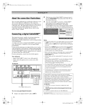
...service (contact your cable operator) TV back panel From digital Cable service To view encrypted digital channels: 1 Connect your cable operator, is capable of receiving analog basic, digital basic, and digital premium cable television programming by your Toshiba television, please contact the following: ...8482; issues with informational screens provided by direct connection to a cable system providing such programming. Most issues can be available until this manual are representative of typical device connections only. DLP Inst (E/F) Web 213:276 If you experience any object or card...
...service (contact your cable operator) TV back panel From digital Cable service To view encrypted digital channels: 1 Connect your cable operator, is capable of receiving analog basic, digital basic, and digital premium cable television programming by your Toshiba television, please contact the following: ...8482; issues with informational screens provided by direct connection to a cable system providing such programming. Most issues can be available until this manual are representative of typical device connections only. DLP Inst (E/F) Web 213:276 If you experience any object or card...
Installation Guide - English
Page 9
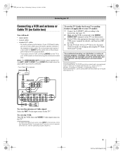
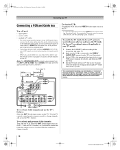
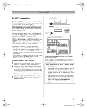
... from the ANT 1, ANT 2, VIDEO 1, and VIDEO 2 terminals when the applicable input mode is connected to the VIDEO/ AUDIO OUT terminals on the TV (see the Operating Guide, Chapter 2. 9 DLP Inst (E/F) Web 213:276 Note: The VIDEO/AUDIO OUT terminals output signals from ANT CH 3 CH 4 OUT to..., DVDs, and other devices, see illustration). 3 Set the VCR to the appropriate line input (refer to your TV model): 1 Connect the G-LINK™ cable according to TV AUDIO L R IN IN OUT L R TV To view the antenna or Cable signal: Select the ANT 1 video input source on the remote control (-
... from the ANT 1, ANT 2, VIDEO 1, and VIDEO 2 terminals when the applicable input mode is connected to the VIDEO/ AUDIO OUT terminals on the TV (see the Operating Guide, Chapter 2. 9 DLP Inst (E/F) Web 213:276 Note: The VIDEO/AUDIO OUT terminals output signals from ANT CH 3 CH 4 OUT to..., DVDs, and other devices, see illustration). 3 Set the VCR to the appropriate line input (refer to your TV model): 1 Connect the G-LINK™ cable according to TV AUDIO L R IN IN OUT L R TV To view the antenna or Cable signal: Select the ANT 1 video input source on the remote control (-
Installation Guide - English
Page 10
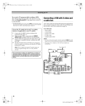
...input (refer to your VCR has S-video, connect an S-video cable (plus the audio cables) instead of video cable to change channels. 10 DLP Inst (E/F) Web 213:276 To program the TV remote control to operate other materials is selected.* From Cable TV Cable box CH 3 IN OUT CH 4 ...Signal splitter IN OUT OUT To view the VCR: Turn ON the VCR. Do not connect both types of the standard ...
...input (refer to your VCR has S-video, connect an S-video cable (plus the audio cables) instead of video cable to change channels. 10 DLP Inst (E/F) Web 213:276 To program the TV remote control to operate other materials is selected.* From Cable TV Cable box CH 3 IN OUT CH 4 ...Signal splitter IN OUT OUT To view the VCR: Turn ON the VCR. Do not connect both types of the standard ...

Installation Guide - English
Page 11
... a VCR, and a satellite receiver Your TV has two sets of the standard video cable. If you want to your VCR's audio out terminal using the component video connections or to record satellite programs: Turn on the TV.* (continued) 11 DLP Inst (E/F) Web 213:276 Operating Guide). Tune the VCR ...to the channel you have component video, connect an S-video cable (plus audio cables) to either set...
... a VCR, and a satellite receiver Your TV has two sets of the standard video cable. If you want to your VCR's audio out terminal using the component video connections or to record satellite programs: Turn on the TV.* (continued) 11 DLP Inst (E/F) Web 213:276 Operating Guide). Tune the VCR ...to the channel you have component video, connect an S-video cable (plus audio cables) to either set...
Installation Guide - English
Page 12
... On Screen™ system does not receive program listings from ANT CH 3 CH 4 OUT to TV AUDIO L R IN IN OUT L R TV 12 DLP Inst (E/F) Web 213:276 Operating Guide). From Cable TV Cable box CH 3 IN OUT CH 4 Signal splitter IN OUT OUT Stereo VCR VIDEO IN from or...the remote control (- DLP_Inst.book Page 12 Wednesday, February 22, 2006 6:18 PM Connecting your TV model): 1 Connect the G-LINK™ cable according to the instructions (- Select the ColorStream HD-1 video input source on the TV* to view the DVD. * To select the video input source, press INPUT on...
... On Screen™ system does not receive program listings from ANT CH 3 CH 4 OUT to TV AUDIO L R IN IN OUT L R TV 12 DLP Inst (E/F) Web 213:276 Operating Guide). From Cable TV Cable box CH 3 IN OUT CH 4 Signal splitter IN OUT OUT Stereo VCR VIDEO IN from or...the remote control (- DLP_Inst.book Page 12 Wednesday, February 22, 2006 6:18 PM Connecting your TV model): 1 Connect the G-LINK™ cable according to the instructions (- Select the ColorStream HD-1 video input source on the TV* to view the DVD. * To select the video input source, press INPUT on...
Installation Guide - English
Page 13
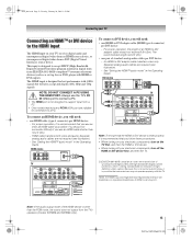
...cables per DVI device - The recommended length is other than 16.4 ft (5m). - HDMI device VIDEO AUDIO L R IN IN HDMI OUT OUT L R TV To connect a DVI device, you will need : • one HDMI-to -DVI adapter cable transfers video only. See "Setting the HDMI™ audio mode" in ... 3:23 PM Connecting your TV Connecting an HDMI™ or DVI device to -DVI adapter cable should not encounter difficulty if you use an HDMI cable shorter than the PCM mode, the sound does not output from the TV's speakers (models 50HM66 and 56HM66 only). 13 DLP Inst (E/F) Web 213:276 You...
...cables per DVI device - The recommended length is other than 16.4 ft (5m). - HDMI device VIDEO AUDIO L R IN IN HDMI OUT OUT L R TV To connect a DVI device, you will need : • one HDMI-to -DVI adapter cable transfers video only. See "Setting the HDMI™ audio mode" in ... 3:23 PM Connecting your TV Connecting an HDMI™ or DVI device to -DVI adapter cable should not encounter difficulty if you use an HDMI cable shorter than the PCM mode, the sound does not output from the TV's speakers (models 50HM66 and 56HM66 only). 13 DLP Inst (E/F) Web 213:276 You...

Installation Guide - English
Page 14
... • dual-wand IR blaster cable • other audio/video cables as a Toshiba infrared remotecontrolled VCRs or DVD player) enclosed within an entertainment center or similar cabinet. Without the IR OUT connection, the device typically would need to use the device's remote control to operate the ...device; - The signal passes from device) TV Notes: • If you do not have a second device, attach the second wand in a similar manner. (See illustration.) 14 DLP Inst (E/F) Web 213:276 To connect the IR blaster cable: 1 Locate the infrared sensor on , move...
... • dual-wand IR blaster cable • other audio/video cables as a Toshiba infrared remotecontrolled VCRs or DVD player) enclosed within an entertainment center or similar cabinet. Without the IR OUT connection, the device typically would need to use the device's remote control to operate the ...device; - The signal passes from device) TV Notes: • If you do not have a second device, attach the second wand in a similar manner. (See illustration.) 14 DLP Inst (E/F) Web 213:276 To connect the IR blaster cable: 1 Locate the infrared sensor on , move...

Installation Guide - English
Page 15
... IR receiver/repeater control system (not included) To operate the TV with this connection, point the Toshiba TV remote control toward the front of the IR receiver/repeater control system. IR receiver/repeater control system 15 DLP Inst (E/F) Web 213:276 VIDEO 2 inputs on TV right side panel To view the camcorder video: Select the VIDEO...
... IR receiver/repeater control system (not included) To operate the TV with this connection, point the Toshiba TV remote control toward the front of the IR receiver/repeater control system. IR receiver/repeater control system 15 DLP Inst (E/F) Web 213:276 VIDEO 2 inputs on TV right side panel To view the camcorder video: Select the VIDEO...

Installation Guide - English
Page 16
...Some audio systems may not output some digital audio sources because of both the TV and the amplifier must be compatible with an external analog audio amplifier to a reasonable listening level. 16 DLP Inst (E/F) Web 213:276 THIS DAMAGE IS NOT COVERED BY YOUR WARRANTY. • The... Settings Advanced Audio Settings Audio Setup 4 In the Optical Output Format field, select either Dolby Digital or PCM, depending on your TV Connecting a digital audio system The TV's DIGITAL AUDIO OUT terminal outputs a Dolby®* Digital g or 2-channel down-mixed PCM (pulse-code modulation) signal for use...
...Some audio systems may not output some digital audio sources because of both the TV and the amplifier must be compatible with an external analog audio amplifier to a reasonable listening level. 16 DLP Inst (E/F) Web 213:276 THIS DAMAGE IS NOT COVERED BY YOUR WARRANTY. • The... Settings Advanced Audio Settings Audio Setup 4 In the Optical Output Format field, select either Dolby Digital or PCM, depending on your TV Connecting a digital audio system The TV's DIGITAL AUDIO OUT terminal outputs a Dolby®* Digital g or 2-channel down-mixed PCM (pulse-code modulation) signal for use...
Installation Guide - English
Page 17
... features with your TV has this step.) 3 If the device turns on , move the remote control slightly to the right and press POWER again. 5 Repeat step 4 until you locate the device's infrared sensor. 17 DLP Inst (E/F) Web 213:276 After you connect your devices to the TV, you have a... VCR, you must connect the G-LINK™ cable from your TV Guide On Screen™ system: • If you have a Cable box, you must...
... features with your TV has this step.) 3 If the device turns on , move the remote control slightly to the right and press POWER again. 5 Repeat step 4 until you locate the device's infrared sensor. 17 DLP Inst (E/F) Web 213:276 After you connect your devices to the TV, you have a... VCR, you must connect the G-LINK™ cable from your TV Guide On Screen™ system: • If you have a Cable box, you must...
Installation Guide - English
Page 18
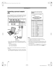
... @ 60Hz - The following signals can be skipped or you to view the image from a PC on the PC before connecting it to the HDMI port. 18 DLP Inst (E/F) Web 213:276 SVGA: 800 5 600 @ 60Hz - Signal names for mini D-sub 15-pin connector Pin assignment for RGB... cannot be connected to the TV, use the PC setting feature (- When connecting a PC to this TV. • An adapter is not needed for connecting a PC. Never connect a PC to the TV. DLP_Inst.book Page 18 Wednesday, February 22, 2006 6:18 PM Connecting your TV Connecting a personal computer (PC) This connection allows you ...
... @ 60Hz - The following signals can be skipped or you to view the image from a PC on the PC before connecting it to the HDMI port. 18 DLP Inst (E/F) Web 213:276 SVGA: 800 5 600 @ 60Hz - Signal names for mini D-sub 15-pin connector Pin assignment for RGB... cannot be connected to the TV, use the PC setting feature (- When connecting a PC to this TV. • An adapter is not needed for connecting a PC. Never connect a PC to the TV. DLP_Inst.book Page 18 Wednesday, February 22, 2006 6:18 PM Connecting your TV Connecting a personal computer (PC) This connection allows you ...
Installation Guide - English
Page 19
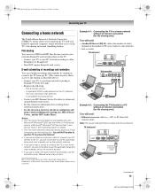
...or other countries. DLP_Inst.book Page 19 Wednesday, February 22, 2006 6:18 PM Connecting your TV Connecting a home network The Toshiba Home Interactive Network Connection (THINC™) feature allows you to network the TV with Microsoft® Windows® 2000 and the Home or Professional version of ... MP3 Audio Player. Home Internet service. - TV back panel Ethernet crossover PC cable (continued) 19 DLP Inst (E/F) Web 213:276 A dedicated POP3 e-mail address for details on the TV. • Connect your TV to your PC directly to the TV, you will not be able to use a...
...or other countries. DLP_Inst.book Page 19 Wednesday, February 22, 2006 6:18 PM Connecting your TV Connecting a home network The Toshiba Home Interactive Network Connection (THINC™) feature allows you to network the TV with Microsoft® Windows® 2000 and the Home or Professional version of ... MP3 Audio Player. Home Internet service. - TV back panel Ethernet crossover PC cable (continued) 19 DLP Inst (E/F) Web 213:276 A dedicated POP3 e-mail address for details on the TV. • Connect your TV to your PC directly to the TV, you will not be able to use a...
Installation Guide - English
Page 20
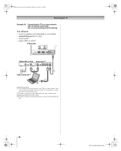
... will need: • coaxial or telephone cable (depending on your modem type) [3] Standard Ethernet (RJ-45) cable [4] Do NOT connect a phone jack directly to the TV's RJ-45 (Ethernet) port. 20 DLP Inst (E/F) Web 213:276 Your switch may be separate from your DSL or cable modem. For assistance, contact your ISP or...
... will need: • coaxial or telephone cable (depending on your modem type) [3] Standard Ethernet (RJ-45) cable [4] Do NOT connect a phone jack directly to the TV's RJ-45 (Ethernet) port. 20 DLP Inst (E/F) Web 213:276 Your switch may be separate from your DSL or cable modem. For assistance, contact your ISP or...
Installation Guide - English
Page 21
... DVI connection 13 E Ethernet (RJ-45) cable 7 G G-LINK™ connection 17 H HDMI cable 7 HDMI™ connection 13 Home network connection 19 I Installation, care, and service 3 IR blaster 14 O Optical audio cable 7 P PC connection 18 R RJ-45 (THINC™) connection .......... 19 Router 20 S Safety 2 Service 4 S-video cable 7 V VCR connection 9, 10, 11, 12 Video cables 7 21 DLP Inst (E/F) Web 213...
... DVI connection 13 E Ethernet (RJ-45) cable 7 G G-LINK™ connection 17 H HDMI cable 7 HDMI™ connection 13 Home network connection 19 I Installation, care, and service 3 IR blaster 14 O Optical audio cable 7 P PC connection 18 R RJ-45 (THINC™) connection .......... 19 Router 20 S Safety 2 Service 4 S-video cable 7 V VCR connection 9, 10, 11, 12 Video cables 7 21 DLP Inst (E/F) Web 213...
