

User Manual
Page 3
.... 960-140 The manual is divided into the following : Handling the LCD module Board layout Pin assignments Keyboard scan/character codes Key layout Wiring diagrams BIOS Rewrite Procedures Reliability iv Appendices The eight appendices describe the following parts: Chapter 1 Hardware Overview describes the system unit and each FRU. Chapter 4 Replacement Procedures...
.... 960-140 The manual is divided into the following : Handling the LCD module Board layout Pin assignments Keyboard scan/character codes Key layout Wiring diagrams BIOS Rewrite Procedures Reliability iv Appendices The eight appendices describe the following parts: Chapter 1 Hardware Overview describes the system unit and each FRU. Chapter 4 Replacement Procedures...

User Manual
Page 7
File No. 960-140 4.13 I/O Adapter Board 4-35 Appendices Appendix A Handling the LCD Module A-1 Appendix B Board Layout B-1 Appendix C Pin Assignments C-1 Appendix D Keyboard Scan/Character Codes D-1 Appendix E Key Layout E-1 Appendix F Wiring Diagrams F-1 Appendix G BIOS Rewrite Procedures G-1 Appendix H Reliability H-1 viii
File No. 960-140 4.13 I/O Adapter Board 4-35 Appendices Appendix A Handling the LCD Module A-1 Appendix B Board Layout B-1 Appendix C Pin Assignments C-1 Appendix D Keyboard Scan/Character Codes D-1 Appendix E Key Layout E-1 Appendix F Wiring Diagrams F-1 Appendix G BIOS Rewrite Procedures G-1 Appendix H Reliability H-1 viii
User Manual
Page 17
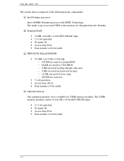
... (Flash EEPROM) • 512 KB, one 512K x 8-bit chip − 256 KB are used for system BIOS − 64 KB are used for VGA-BIOS − 8 KB are used for plug and play data area − 8 KB are used for password security − 16 KB are used for 32MB memory ...
... (Flash EEPROM) • 512 KB, one 512K x 8-bit chip − 256 KB are used for system BIOS − 64 KB are used for VGA-BIOS − 8 KB are used for plug and play data area − 8 KB are used for password security − 16 KB are used for 32MB memory ...

User Manual
Page 48
...tests each IC on the display, perform Check 1. If an error message is shown on the system board and initializes it. If Toshiba MS-DOS or Toshiba Windows 95 is damaged. If you press the F1 key as the message instructs. If any other error message displays, perform Check... 3. These errors occur when the system configuration preserved in the BIOS ROM. Then press [F1] key ...... (e) *** Bad time function *** Check system. Then press [F1] ...
...tests each IC on the display, perform Check 1. If an error message is shown on the system board and initializes it. If Toshiba MS-DOS or Toshiba Windows 95 is damaged. If you press the F1 key as the message instructs. If any other error message displays, perform Check... 3. These errors occur when the system configuration preserved in the BIOS ROM. Then press [F1] key ...... (e) *** Bad time function *** Check system. Then press [F1] ...
User Manual
Page 54
... to SM-RAM Timer initialization Get version of embedded controller and PS microprocessor Set default value to embedded controller Toshiba special register initialization Grant SMI from docking port and Selectable Bay VGA BIOS initialization Selectable Bay lock check Displaying logo PnP automatic configuration PnP ISA card isolation Search assignable resource and card...
... to SM-RAM Timer initialization Get version of embedded controller and PS microprocessor Set default value to embedded controller Toshiba special register initialization Grant SMI from docking port and Selectable Bay VGA BIOS initialization Selectable Bay lock check Displaying logo PnP automatic configuration PnP ISA card isolation Search assignable resource and card...
User Manual
Page 55
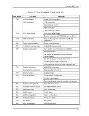
... File No. 960-140 Table 2-3 Printer port LED boot mode status (5/5) LED Status Test item A0h Boot password C0h External I/O check A6h BIOS information update FEh System ROM check FFh End Message Boot password External I/O check Set font address Set shadow RAM size Set expansion memory size to... CMOS System resource update Set extended memory size to runtime BIOS for INT15h ACPI table update Set SCT area to runtime BIOS Set battery save mode Send date to PS microprocessor Close PCI device configuration area Protect system...
... File No. 960-140 Table 2-3 Printer port LED boot mode status (5/5) LED Status Test item A0h Boot password C0h External I/O check A6h BIOS information update FEh System ROM check FFh End Message Boot password External I/O check Set font address Set shadow RAM size Set expansion memory size to... CMOS System resource update Set extended memory size to runtime BIOS for INT15h ACPI table update Set SCT area to runtime BIOS Set battery save mode Send date to PS microprocessor Close PCI device configuration area Protect system...
User Manual
Page 56
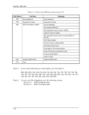
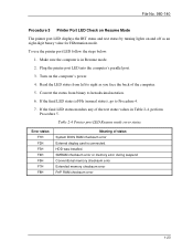
... F2H F3H F4H F5H F7H F8H Meaning of the test status values in Resume mode. 2. If the final LED status matches any of status System BIOS RAM checksum error External display card is connected. If the final LED status is in Table 2-4, perform Procedure 5. HDD was installed. To use the printer...
... F2H F3H F4H F5H F7H F8H Meaning of the test status values in Resume mode. 2. If the final LED status matches any of status System BIOS RAM checksum error External display card is connected. If the final LED status is in Table 2-4, perform Procedure 5. HDD was installed. To use the printer...

User Manual
Page 84
... the result codes in Chapter 2. 3-9 Refer to execute and press Enter. Subtest 05 Thermistor Check This subtest reads the thermistor connect check status of the BIOS ROM on the screen. If the data indicates the connector is open or shorted, it with the original data. Subtest 06 Quick Charge This subtest...
... the result codes in Chapter 2. 3-9 Refer to execute and press Enter. Subtest 05 Thermistor Check This subtest reads the thermistor connect check status of the BIOS ROM on the screen. If the data indicates the connector is open or shorted, it with the original data. Subtest 06 Quick Charge This subtest...

User Manual
Page 130
... ROM Version 6. KBC Version 7. Modem Type 15. Selectbay Unit 18. The number of floppy disk drives 16. The number of ASYNC ports 12. VGA Controller 3. BIOS ROM Version (1st ID, 2nd ID) 5. PS Microprocessor Version 8. The number of hard disk drives 17. Sound System 10. 3 3.23 System Configuration File No. 960...
... ROM Version 6. KBC Version 7. Modem Type 15. Selectbay Unit 18. The number of floppy disk drives 16. The number of ASYNC ports 12. VGA Controller 3. BIOS ROM Version (1st ID, 2nd ID) 5. PS Microprocessor Version 8. The number of hard disk drives 17. Sound System 10. 3 3.23 System Configuration File No. 960...

User Manual
Page 131
Processor Type = XXXX ** - VGA Controller = XXXX * - X Hard Dis k Drive(s) #1 Cylinder = XXXXX, Head = XX, Sector =XX #2 Cylinder = XXXXX, Head = XX, Sector =XX * - BIOS ROM Version = V .XX 1st ID = XXH, 2nd ID = XXH * - Total Memory Size = XXXXXMB( Converntional Memory = XXXXX KB) ** *****- BOOT ROM Version = VX.XX * - Sound System = X Prin ...
Processor Type = XXXX ** - VGA Controller = XXXX * - X Hard Dis k Drive(s) #1 Cylinder = XXXXX, Head = XX, Sector =XX #2 Cylinder = XXXXX, Head = XX, Sector =XX * - BIOS ROM Version = V .XX 1st ID = XXH, 2nd ID = XXH * - Total Memory Size = XXXXXMB( Converntional Memory = XXXXX KB) ** *****- BOOT ROM Version = VX.XX * - Sound System = X Prin ...

User Manual
Page 194
File No. 960-140 E.7 Scandinavian (SC) Keyboard E-4 E.8 Swiss-German (SL) Keyboard E-4 Appendix F Wiring Diagrams F-1 F.1 Parallel Port Wraparound Connector F-1 F.2 Serial Port Wraparound Connector F-1 F.3 Serial Port Direct Cable (9-Pin to 9-Pin F-2 F.4 Serial Port Direct Cable (9-Pin to 25-Pin F-2 Appendix G BIOS Rewrite Procedures G-1 Appendix H Reliability H-1 App-iv
File No. 960-140 E.7 Scandinavian (SC) Keyboard E-4 E.8 Swiss-German (SL) Keyboard E-4 Appendix F Wiring Diagrams F-1 F.1 Parallel Port Wraparound Connector F-1 F.2 Serial Port Wraparound Connector F-1 F.3 Serial Port Direct Cable (9-Pin to 9-Pin F-2 F.4 Serial Port Direct Cable (9-Pin to 25-Pin F-2 Appendix G BIOS Rewrite Procedures G-1 Appendix H Reliability H-1 App-iv

User Manual
Page 205
Mark (A) (B) (C) (D) (E) (F) (G) File No. 960-140 Table B-1 System board ICs and connectors (front) Number IC3 to 6 IC300 PJ200 PJ301 PJ303 PJ500 PJ510 Name System RAM BIOS ROM Docking interface connector HDD connector PC card connector DC-IN connector Main battery connector Mark (A) (B) (C) (D) (E) (F) (G) (H) (I) (J) (K) (L) (M) (N) (O) (P) (Q) (R) (S) (T) Table B-2 System board ICs and connectors (back) Number F256 ...
Mark (A) (B) (C) (D) (E) (F) (G) File No. 960-140 Table B-1 System board ICs and connectors (front) Number IC3 to 6 IC300 PJ200 PJ301 PJ303 PJ500 PJ510 Name System RAM BIOS ROM Docking interface connector HDD connector PC card connector DC-IN connector Main battery connector Mark (A) (B) (C) (D) (E) (F) (G) (H) (I) (J) (K) (L) (M) (N) (O) (P) (Q) (R) (S) (T) Table B-2 System board ICs and connectors (back) Number F256 ...

User Manual
Page 233
... displays, insert the diagnostics disk into the FDD, then press Enter to rewrite the system BIOS program when you need the following tool: Diagnostics disk for the computer Rewriting the BIOS 1. When the process is completed, eject the diagnostics disk and press the reset switch to the computer. 3. G-1... Turn off the power to restart the system. Tools To rewrite the BIOS, you update the system BIOS. Turn on the power while holding down the F12 key. (Keep holding down the key until the system speaker sounds a beep.) ...
... displays, insert the diagnostics disk into the FDD, then press Enter to rewrite the system BIOS program when you need the following tool: Diagnostics disk for the computer Rewriting the BIOS 1. When the process is completed, eject the diagnostics disk and press the reset switch to the computer. 3. G-1... Turn off the power to restart the system. Tools To rewrite the BIOS, you update the system BIOS. Turn on the power while holding down the F12 key. (Keep holding down the key until the system speaker sounds a beep.) ...


