
User Manual
Page 4
For example: Read Only Memory (ROM) Keys Keys are enclosed in boldface type. File No. 960-140 Conventions This manual uses the following their definition. Acronyms On the first appearance ...
For example: Read Only Memory (ROM) Keys Keys are enclosed in boldface type. File No. 960-140 Conventions This manual uses the following their definition. Acronyms On the first appearance ...
User Manual
Page 5
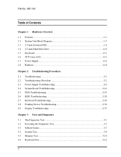
... 2.7 Keyboard Troubleshooting 2-34 2.8 Pointing Device Troubleshooting 2-36 2.9 Display Troubleshooting 2-37 Chapter 3 Tests and Diagnostics 3.1 The Diagnostic Test 3-1 3.2 Executing the Diagnostic Test 3-3 3.3 Subtest Names...3-7 3.4 System Test...3-9 3.5 Memory Test ...3-10 3.6 Keyboard Test ...3-12 vi
... 2.7 Keyboard Troubleshooting 2-34 2.8 Pointing Device Troubleshooting 2-36 2.9 Display Troubleshooting 2-37 Chapter 3 Tests and Diagnostics 3.1 The Diagnostic Test 3-1 3.2 Executing the Diagnostic Test 3-3 3.3 Subtest Names...3-7 3.4 System Test...3-9 3.5 Memory Test ...3-10 3.6 Keyboard Test ...3-12 vi

User Manual
Page 6
... Utilities...3-47 3.21 Running Test ...3-49 3.22 Floppy Disk Drive Utilities 3-51 3.23 System Configuration 3-56 3.24 SETUP...3-58 Chapter 4 Replacement Procedures 4.1 Overview...4-1 4.2 HDD...4-8 4.3 Optional Memory Module 4-10 4.4 Keyboard...4-12 4.5 Display Assembly 4-13 4.6 RTC Battery...4-17 4.7 System Board, Heat Sink and PC Card Slot 4-18 4.8 Display Mask...4-20 4.9 FL Inverter Board...
... Utilities...3-47 3.21 Running Test ...3-49 3.22 Floppy Disk Drive Utilities 3-51 3.23 System Configuration 3-56 3.24 SETUP...3-58 Chapter 4 Replacement Procedures 4.1 Overview...4-1 4.2 HDD...4-8 4.3 Optional Memory Module 4-10 4.4 Keyboard...4-12 4.5 Display Assembly 4-13 4.6 RTC Battery...4-17 4.7 System Board, Heat Sink and PC Card Slot 4-18 4.8 Display Mask...4-20 4.9 FL Inverter Board...

User Manual
Page 12
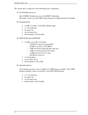
...® Windows® 95. It supports software that have special functions in the memory slot. 1-1 HDD The computer has a 2.5-inch HDD with 32MB of Extend Data Out (EDO) DRAM. File No. 960-140 1 Features 1.1 Features The computer uses Toshiba's advanced Large Scale Integration (LSI), and Complementary Metal-Oxide Semiconductor (CMOS) technology extensively...
...® Windows® 95. It supports software that have special functions in the memory slot. 1-1 HDD The computer has a 2.5-inch HDD with 32MB of Extend Data Out (EDO) DRAM. File No. 960-140 1 Features 1.1 Features The computer uses Toshiba's advanced Large Scale Integration (LSI), and Complementary Metal-Oxide Semiconductor (CMOS) technology extensively...
User Manual
Page 17
... reserved • 5 volt operation • Access time 120 ns • Data transfer is 8-bit width Optional memory One expansion memory slot is available for 32MB memory modules. The 32MB memory modules consist of four 4M x 16-bit EDO DRAM chips. • 3.3 volt operation • No parity bit • Access time 60 ns • Data...
... reserved • 5 volt operation • Access time 120 ns • Data transfer is 8-bit width Optional memory One expansion memory slot is available for 32MB memory modules. The 32MB memory modules consist of four 4M x 16-bit EDO DRAM chips. • 3.3 volt operation • No parity bit • Access time 60 ns • Data...
User Manual
Page 18
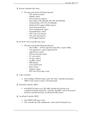
... control − RTC One T9934 chip is used Video Controller • The NeoMagic NM2160 chip is used . • This controller provides simultaneous control of video memory using a 128-bit data path. Keyboard Controller (KBC) • One M38813S chip is used. The Video controller incorporates 2MB of the Pointing Device. 1-7 The KBC...
... control − RTC One T9934 chip is used Video Controller • The NeoMagic NM2160 chip is used . • This controller provides simultaneous control of video memory using a 128-bit data path. Keyboard Controller (KBC) • One M38813S chip is used. The Video controller incorporates 2MB of the Pointing Device. 1-7 The KBC...
User Manual
Page 26
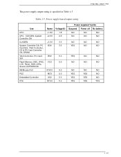
... CPU, CLKGEN, System Controller GA CLKGEN System Controller GA, PC Card Slot, VGA Controller, I/O & PC Card Controller GA, DRAM VGA Controller, PC Card Slot Flash Memory, KBC, IPSC, LCD Panel, HDD, LEDs, Sound, E2PROM,GA KB/Mouse Port PSC Embedded Controller RTC Name +1.8V +2.5V +3.3V B3V B5V VCC IFVCC MCV...
... CPU, CLKGEN, System Controller GA CLKGEN System Controller GA, PC Card Slot, VGA Controller, I/O & PC Card Controller GA, DRAM VGA Controller, PC Card Slot Flash Memory, KBC, IPSC, LCD Panel, HDD, LEDs, Sound, E2PROM,GA KB/Mouse Port PSC Embedded Controller RTC Name +1.8V +2.5V +3.3V B3V B5V VCC IFVCC MCV...
User Manual
Page 28
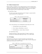
... period of the following occurs, the Main Battery quick charge process stops. 1. Table 1-7 Time required for quick charges Status Quick charge 1(power off or in memory while the computer is removed. 3. The Main Battery becomes fully charged. 2. Trickle Battery Charge When the main battery is fully charged and the AC adapter...
... period of the following occurs, the Main Battery quick charge process stops. 1. Table 1-7 Time required for quick charges Status Quick charge 1(power off or in memory while the computer is removed. 3. The Main Battery becomes fully charged. 2. Trickle Battery Charge When the main battery is fully charged and the AC adapter...
User Manual
Page 37
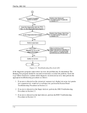
... an error is detected on the hard disk test, perform the HDD Troubleshooting Procedures in Section 2.4. 2. If an error is detected on the system test, memory test, display test,async test, printer test, expansion test, sound test or real timer test, perform the System Board Troubleshooting Procedures in Section 2.6. 1-4 Check the...
... an error is detected on the hard disk test, perform the HDD Troubleshooting Procedures in Section 2.4. 2. If an error is detected on the system test, memory test, display test,async test, printer test, expansion test, sound test or real timer test, perform the System Board Troubleshooting Procedures in Section 2.6. 1-4 Check the...

User Manual
Page 48
If Toshiba MS-DOS or Toshiba Windows 95 is properly loaded, go to set the system ...power is turned on, the system performs the Initial Reliability Test (IRT) installed in the RTC memory (CMOS type memory) is not the same as the actual configuration or when the data is lost because the battery ...replace the RTC battery. Then press [F1] key ...... (c) *** Bad configuration *** Check system. Then press [F1] key ...... (d) *** Bad memory size *** Check system. Then press [F1] key ...... (e) *** Bad time function *** Check system. Check 2 If the following error messages displays...
If Toshiba MS-DOS or Toshiba Windows 95 is properly loaded, go to set the system ...power is turned on, the system performs the Initial Reliability Test (IRT) installed in the RTC memory (CMOS type memory) is not the same as the actual configuration or when the data is lost because the battery ...replace the RTC battery. Then press [F1] key ...... (c) *** Bad configuration *** Check system. Then press [F1] key ...... (d) *** Bad memory size *** Check system. Then press [F1] key ...... (e) *** Bad time function *** Check system. Check 2 If the following error messages displays...
User Manual
Page 49
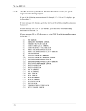
... ERROR (3) TIMER CH.2 OUT ERROR (4) CMOS CHECKSUM ERROR (5) CMOS BAD BATTERY ERROR (6) FIRST 64KB MEMORY ERROR (7) FIRST 64KB MEMORY PARITY ERROR (8) VRAM ERROR (9) SYSTEM MEMORY ERROR (10) SYSTEM MEMORY PARITY ERROR (11) EXTENDED MEMORY ERROR (12) EXTENDED MEMORY PARITY ERROR (13) DMA PAGE REGISTER ERROR (14) DMAC #1 ERROR (15) DMAC #2 ERROR (16) PIC #1 ERROR (17) PIC...
... ERROR (3) TIMER CH.2 OUT ERROR (4) CMOS CHECKSUM ERROR (5) CMOS BAD BATTERY ERROR (6) FIRST 64KB MEMORY ERROR (7) FIRST 64KB MEMORY PARITY ERROR (8) VRAM ERROR (9) SYSTEM MEMORY ERROR (10) SYSTEM MEMORY PARITY ERROR (11) EXTENDED MEMORY ERROR (12) EXTENDED MEMORY PARITY ERROR (13) DMA PAGE REGISTER ERROR (14) DMAC #1 ERROR (15) DMAC #2 ERROR (16) PIC #1 ERROR (17) PIC...
User Manual
Page 50
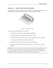
Plug the printer port LED into the computer's parallel port. 2. In this instance, the IRT indicates an error has been detected during the system memory test. 1-17 If the final LED status is detected by turning lights on and off as you are facing the back of the test status ...
Plug the printer port LED into the computer's parallel port. 2. In this instance, the IRT indicates an error has been detected during the system memory test. 1-17 If the final LED status is detected by turning lights on and off as you are facing the back of the test status ...
User Manual
Page 54
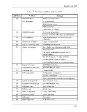
... in IRT BIOS to runtime BIOS Video card recognition and wait for VGA chip initialization Output code generation First 64 KB memory check Store CMOS error information to SM-RAM Timer initialization Get version of embedded controller and PS microprocessor Set default value to ...embedded controller Toshiba special register initialization Grant SMI from docking port and Selectable Bay VGA BIOS initialization Selectable Bay lock check Displaying logo PnP automatic...
... in IRT BIOS to runtime BIOS Video card recognition and wait for VGA chip initialization Output code generation First 64 KB memory check Store CMOS error information to SM-RAM Timer initialization Get version of embedded controller and PS microprocessor Set default value to ...embedded controller Toshiba special register initialization Grant SMI from docking port and Selectable Bay VGA BIOS initialization Selectable Bay lock check Displaying logo PnP automatic...
User Manual
Page 55
... update FEh System ROM check FFh End Message Boot password External I/O check Set font address Set shadow RAM size Set expansion memory size to CMOS System resource update Set extended memory size to runtime BIOS for INT15h ACPI table update Set SCT area to runtime BIOS Set battery save mode Send date...
... update FEh System ROM check FFh End Message Boot password External I/O check Set font address Set shadow RAM size Set expansion memory size to CMOS System resource update Set extended memory size to runtime BIOS for INT15h ACPI table update Set SCT area to runtime BIOS Set battery save mode Send date...
User Manual
Page 56
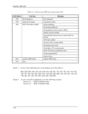
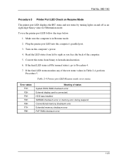
... the computer. 5. If the final LED status matches any of the test status values in Resume mode. 2. SMRAM checksum error or memory error during suspend Conventional memory checksum error Extended memory checksum error PnP RAM checksum error 1-23 File No. 960-140 Procedure 3 Printer Port LED Check on Resume Mode The printer port...
... the computer. 5. If the final LED status matches any of the test status values in Resume mode. 2. SMRAM checksum error or memory error during suspend Conventional memory checksum error Extended memory checksum error PnP RAM checksum error 1-23 File No. 960-140 Procedure 3 Printer Port LED Check on Resume Mode The printer port...
User Manual
Page 57
... steps described in Chapter 4, Replacement Procedures and replace the system board with a new one. 1-24 ASYNC test 8. Keyboard test 4. Floppy Disk test 6. NDP test 11. Memory test 3. Printer test 7. Display test 5.
... steps described in Chapter 4, Replacement Procedures and replace the system board with a new one. 1-24 ASYNC test 8. Keyboard test 4. Floppy Disk test 6. NDP test 11. Memory test 3. Printer test 7. Display test 5.
User Manual
Page 74
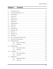
File No. 960-140 Chapter 3 Contents 3.1 The Diagnostic Test 3-1 3.2 Executing the Diagnostic Test 3-3 3.3 Subtest Names...3-7 3.4 System Test...3-9 3.5 Memory Test ...3-10 3.6 Keyboard Test ...3-12 3.7 Display Test...3-16 3.8 Floppy Disk Test 3-20 3.9 Printer Test...3-22 3.10 Async Test...3-24 3.11 Hard Disk Test ...3-26 3.12 ...
File No. 960-140 Chapter 3 Contents 3.1 The Diagnostic Test 3-1 3.2 Executing the Diagnostic Test 3-3 3.3 Subtest Names...3-7 3.4 System Test...3-9 3.5 Memory Test ...3-10 3.6 Keyboard Test ...3-12 3.7 Display Test...3-16 3.8 Floppy Disk Test 3-20 3.9 Printer Test...3-22 3.10 Async Test...3-24 3.11 Hard Disk Test ...3-26 3.12 ...

User Manual
Page 76
... CLEANING LOG UTILITIES RUNNING TEST FDD UTILITIES SYSTEM CONFIGURATION EXIT TO MS-DOS SETUP The DIAGNOSTIC TEST MENU contains the following functional tests: SYSTEM TEST MEMORY TEST KEYBOARD TEST DISPLAY TEST FLOPPY DISK TEST PRINTER TEST ASYNC TEST HARD DISK TEST REAL TIMER TEST NDP TEST EXPANSION TEST SOUND TEST 3-1 File...
... CLEANING LOG UTILITIES RUNNING TEST FDD UTILITIES SYSTEM CONFIGURATION EXIT TO MS-DOS SETUP The DIAGNOSTIC TEST MENU contains the following functional tests: SYSTEM TEST MEMORY TEST KEYBOARD TEST DISPLAY TEST FLOPPY DISK TEST PRINTER TEST ASYNC TEST HARD DISK TEST REAL TIMER TEST NDP TEST EXPANSION TEST SOUND TEST 3-1 File...
User Manual
Page 79
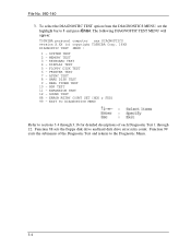
... Test and returns to 1 and press Enter. Function 99 exits the submenus of each Diagnostic Test 1 through 12. The following DIAGNOSTIC TEST MENU will appear: TOSHIBA personal computer xxx DIAGNOSTICS version X.XX (c) copyright TOSHIBA Corp. 19XX DIAGNOSTIC TEST MENU : 1 - MEMORY TEST 3 - KEYBOARD TEST 4 - REAL TIMER TEST 10 - EXPANSION TEST 12 - SOUND TEST 88 -
... Test and returns to 1 and press Enter. Function 99 exits the submenus of each Diagnostic Test 1 through 12. The following DIAGNOSTIC TEST MENU will appear: TOSHIBA personal computer xxx DIAGNOSTICS version X.XX (c) copyright TOSHIBA Corp. 19XX DIAGNOSTIC TEST MENU : 1 - MEMORY TEST 3 - KEYBOARD TEST 4 - REAL TIMER TEST 10 - EXPANSION TEST 12 - SOUND TEST 88 -
User Manual
Page 82
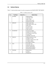
... BUS Master Transfaer Sequential read Sequential read/write Random address/data Write specified address Read specified address Ripple pattern Function Wraparound 3-7 Test Name 1 SYSTEM 2 MEMORY 3 KEYBOARD 4 DISPLAY 5 FDD 6 PRINTER Subtest No. 01 05 06 07 08 01 02 03 04 05 06 01 02 03 04 05 01...check Quick charge DMI read (Not used) DMI write (Not used) RAM constant data RAM address pattern data RAM refresh Protected mode Memory module Cache memory Pressed key display Pressed key code display PS/2 Mouse connect check Pointing Stick USB Warp around test VRAM read/write for VGA Gradation for...
... BUS Master Transfaer Sequential read Sequential read/write Random address/data Write specified address Read specified address Ripple pattern Function Wraparound 3-7 Test Name 1 SYSTEM 2 MEMORY 3 KEYBOARD 4 DISPLAY 5 FDD 6 PRINTER Subtest No. 01 05 06 07 08 01 02 03 04 05 06 01 02 03 04 05 01...check Quick charge DMI read (Not used) DMI write (Not used) RAM constant data RAM address pattern data RAM refresh Protected mode Memory module Cache memory Pressed key display Pressed key code display PS/2 Mouse connect check Pointing Stick USB Warp around test VRAM read/write for VGA Gradation for...


