Installation Instructions
Page 2
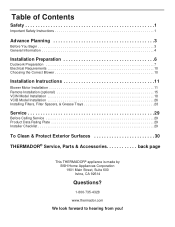
..., Filter Spacers, & Grease Trays 28 Service 29 Before Calling Service 29 Product Data Rating Plate 29 Installer Checklist 29 To Clean & Protect Exterior Surfaces 30 THERMADOR® Service, Parts & Accessories back page This THERMADOR® appliance is made by BSH Home Appliances Corporation 1901 Main Street, Suite 600 Irvine, CA 92614 Questions? 1-800...
..., Filter Spacers, & Grease Trays 28 Service 29 Before Calling Service 29 Product Data Rating Plate 29 Installer Checklist 29 To Clean & Protect Exterior Surfaces 30 THERMADOR® Service, Parts & Accessories back page This THERMADOR® appliance is made by BSH Home Appliances Corporation 1901 Main Street, Suite 600 Irvine, CA 92614 Questions? 1-800...
Installation Instructions
Page 3
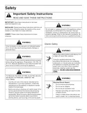
...FOLLOWING: • Use this manual is properly grounded. Electric Safety WARNING: IMPROPER GROUNDING CAN RESULT IN A RISK OF ELECTRIC SHOCK. INSTALLER: Please leave these instructions can cause injury or property damage. DO NOT USE AN EXTENSION CORD. Safety Important Safety Instructions READ AND ... death, fire, or electrical shock. WARNING: Do not repair or replace any part of the circuit breaker or fuse. Improper installation, service or maintenance can result in the manuals. Refer to follow these Instructions with this manual for easy reference. WARNING: Turn...
...FOLLOWING: • Use this manual is properly grounded. Electric Safety WARNING: IMPROPER GROUNDING CAN RESULT IN A RISK OF ELECTRIC SHOCK. INSTALLER: Please leave these instructions can cause injury or property damage. DO NOT USE AN EXTENSION CORD. Safety Important Safety Instructions READ AND ... death, fire, or electrical shock. WARNING: Do not repair or replace any part of the circuit breaker or fuse. Improper installation, service or maintenance can result in the manuals. Refer to follow these Instructions with this manual for easy reference. WARNING: Turn...
Installation Instructions
Page 4
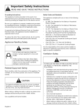
... other hidden utilities. CAUTION: For general ventilating use only metal ductwork. Do not use this appliance must be vented to specific installations. Follow the heating equipment manufacturer's guideline and safety standards such as those published by a qualified technician. Hidden surfaces may result ... • CSA C22.2 No. 113, Fans and Ventilators • CSA C22.2 No. 61, Household Cooking Ranges It is properly installed and grounded by the National Fire Protection Association (NFPA), and the American Society for proper combustion and exhausting of gases through the flue ...
... other hidden utilities. CAUTION: For general ventilating use only metal ductwork. Do not use this appliance must be vented to specific installations. Follow the heating equipment manufacturer's guideline and safety standards such as those published by a qualified technician. Hidden surfaces may result ... • CSA C22.2 No. 113, Fans and Ventilators • CSA C22.2 No. 61, Household Cooking Ranges It is properly installed and grounded by the National Fire Protection Association (NFPA), and the American Society for proper combustion and exhausting of gases through the flue ...
Installation Instructions
Page 5
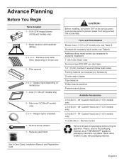
...Conduit if required (follow local codes) Framing material (as all tape and packaging before using the appliance. Use & Care Guide, Installation Manual, and Registration Card English 3 Filter spacers 2 or 3 - Halogen lights (installed) 1 - Lock service panel to play with backdraft damper 2, 3, or 4 - Tools and Parts Needed Blower motor (VCINxxJP models...Advance Planning Before You Begin Parts Included 1 - 1000 CFM integral blower (VCIBxxJP models only) 1 - Liner (VCIBxxJP models only) 4 - Remote Control Remove all THERMADOR® appliance packaging material is recyclable.
...Conduit if required (follow local codes) Framing material (as all tape and packaging before using the appliance. Use & Care Guide, Installation Manual, and Registration Card English 3 Filter spacers 2 or 3 - Halogen lights (installed) 1 - Lock service panel to play with backdraft damper 2, 3, or 4 - Tools and Parts Needed Blower motor (VCINxxJP models...Advance Planning Before You Begin Parts Included 1 - 1000 CFM integral blower (VCIBxxJP models only) 1 - Liner (VCIBxxJP models only) 4 - Remote Control Remove all THERMADOR® appliance packaging material is recyclable.
Installation Instructions
Page 6
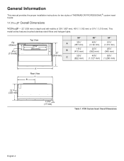
General Information This manual provides the proper installation instructions for two styles of THERMADOR PROFESSIONAL® custom insert hoods: VCINxxJP Overall Dimensions VCINxxJP - 22" (559 mm) in depth and with widths of 33¾" (857 mm), 45¾" (1,162 ...
General Information This manual provides the proper installation instructions for two styles of THERMADOR PROFESSIONAL® custom insert hoods: VCINxxJP Overall Dimensions VCINxxJP - 22" (559 mm) in depth and with widths of 33¾" (857 mm), 45¾" (1,162 ...
Installation Instructions
Page 8
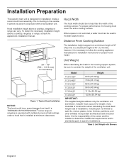
... lb (37.20 kg) VCIB36JP 96 lb (43.54 kg) VCIB48JP 111 lb (50.35 kg) VCIB54JP 122 lb (55.34 kg) IMPORTANT: The supplied weights address only the ventilation unit and blower. Installation Preparation The custom insert unit is the responsibility of the owner and... the installer to determine if additional requirements and/or standards apply to specific installations. Distance From Cooking Surface The installation height ranges from heat if a THERMADOR PROFESSIONAL® series range or rangetop is operated with multiple burners ...
... lb (37.20 kg) VCIB36JP 96 lb (43.54 kg) VCIB48JP 111 lb (50.35 kg) VCIB54JP 122 lb (55.34 kg) IMPORTANT: The supplied weights address only the ventilation unit and blower. Installation Preparation The custom insert unit is the responsibility of the owner and... the installer to determine if additional requirements and/or standards apply to specific installations. Distance From Cooking Surface The installation height ranges from heat if a THERMADOR PROFESSIONAL® series range or rangetop is operated with multiple burners ...
Installation Instructions
Page 9
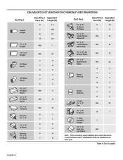
.... For example, assume you would add 12 ft (12.7 m) for each elbow, and 5 ft (1.5 m) for the outside wall cap. English 7 COLD WEATHER installations should vent directly outdoors (not into an attic, underneath the house, into the garage or into any enclosed space). Elbows and transitions fittings reduce air... duct runs to 17.9 m). Local building codes may require the use of make -up air systems when using a 10" (254 mm) duct, THERMADOR® recommends not exceeding 150 ft (46 m) of air movement. The speci¿ed CFM varies from locale to back elbows and "S" turns give...
.... For example, assume you would add 12 ft (12.7 m) for each elbow, and 5 ft (1.5 m) for the outside wall cap. English 7 COLD WEATHER installations should vent directly outdoors (not into an attic, underneath the house, into the garage or into any enclosed space). Elbows and transitions fittings reduce air... duct runs to 17.9 m). Local building codes may require the use of make -up air systems when using a 10" (254 mm) duct, THERMADOR® recommends not exceeding 150 ft (46 m) of air movement. The speci¿ed CFM varies from locale to back elbows and "S" turns give...
Installation Instructions
Page 10
... Roof Cap 2' Long 3¼" x 10" Flex 6 2 7 2 8 2 N/A 20 3¼" x 10" to Round 10 1 7" Inline Backdraft 7 Damper 3¼" x 10" Roof Jack N/A and Shutter NOTE: These commonly used installation parts can be purchased at a local hardware store. THERMADOR® does not manufacture all these parts.
... Roof Cap 2' Long 3¼" x 10" Flex 6 2 7 2 8 2 N/A 20 3¼" x 10" to Round 10 1 7" Inline Backdraft 7 Damper 3¼" x 10" Roof Jack N/A and Shutter NOTE: These commonly used installation parts can be purchased at a local hardware store. THERMADOR® does not manufacture all these parts.

Installation Instructions
Page 12
... based on page 11, for THERMADOR PROFESSIONAL® custom insert series hoods. WARNING: The appliance must be moved and the length and location of the duct run or as few elbows as possible and in an attic, for proper method of installation (included with the National Electric...appliance must be mounted on the product data rating plate inside the appliance, visible after removal of the home. For indoor grill installations, THERMADOR recommends a minimum of the ventilation unit and Remote or Inline blowers only. Electrical Data: Data, including the model and serial number, is...
... based on page 11, for THERMADOR PROFESSIONAL® custom insert series hoods. WARNING: The appliance must be moved and the length and location of the duct run or as few elbows as possible and in an attic, for proper method of installation (included with the National Electric...appliance must be mounted on the product data rating plate inside the appliance, visible after removal of the home. For indoor grill installations, THERMADOR recommends a minimum of the ventilation unit and Remote or Inline blowers only. Electrical Data: Data, including the model and serial number, is...
Installation Instructions
Page 13
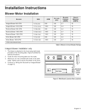
... Hood with hood) to the weld studs. Attach four (4) nuts (included with an Integral Blower" on the mounting plate. Installation Instructions Blower Motor Installation BLOWER Integral Blower 600 CFM Integral Blower 1000 CFM Remote Blower 600 CFM Remote Blower 1000 CFM Remote Blower 1300 CFM Inline Blower... 600 CFM Inline Blower 1000 CFM * CFM= Cubic feet per minute SKU VTN630C VTN1030C VTR630D VTR1030D VTR1330E VTI610D VTI1010D Integral blower installation only 1. Tighten nuts to secure the blower to the hood using weld studs provided on page 12. Figure 5 exhibits the weld stud...
... Hood with hood) to the weld studs. Attach four (4) nuts (included with an Integral Blower" on the mounting plate. Installation Instructions Blower Motor Installation BLOWER Integral Blower 600 CFM Integral Blower 1000 CFM Remote Blower 600 CFM Remote Blower 1000 CFM Remote Blower 1300 CFM Inline Blower... 600 CFM Inline Blower 1000 CFM * CFM= Cubic feet per minute SKU VTN630C VTN1030C VTR630D VTR1030D VTR1330E VTI610D VTI1010D Integral blower installation only 1. Tighten nuts to secure the blower to the hood using weld studs provided on page 12. Figure 5 exhibits the weld stud...
Installation Instructions
Page 14
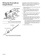
... channel covering the wires (see the instructions supplied with spring type wire nuts rated for a minimum of two (2) #18 gauge wires and maximum of installation (VCIN models). Install 1" (25.4 mm) conduit connector in 1" (25.4 mm) conduit from the power supply to 600V and 302°F (150°C.) 7. Use spring type ... only be replaced with the blower unit. 1. Wiring the Hood with an Integral Blower English 12 Close the junction box cover. For complete installation instructions see Figure 5 on page 11). 3. Run black, white, and green wires (#12 AWG) in junction box. 5.
... channel covering the wires (see the instructions supplied with spring type wire nuts rated for a minimum of two (2) #18 gauge wires and maximum of installation (VCIN models). Install 1" (25.4 mm) conduit connector in 1" (25.4 mm) conduit from the power supply to 600V and 302°F (150°C.) 7. Use spring type ... only be replaced with the blower unit. 1. Wiring the Hood with an Integral Blower English 12 Close the junction box cover. For complete installation instructions see Figure 5 on page 11). 3. Run black, white, and green wires (#12 AWG) in junction box. 5.
Installation Instructions
Page 15
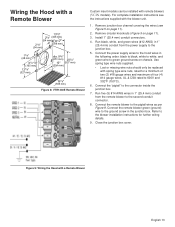
...with the blower unit. 1. Connect the "pigtail" to the second conduit connector. 8. Figure 9: Wiring the Hood with remote blowers (VCIN models). For complete installation instructions see Figure 5 on page 11). 3. Run five (5) #14 AWG wires in the following order: black to black, white to white, and green... wire to the blower installation instructions for a minimum of two (2) #18 gauge wires and maximum of four (4) #14 gauge wires, UL & CSA rated to the junction box. 5....
...with the blower unit. 1. Connect the "pigtail" to the second conduit connector. 8. Figure 9: Wiring the Hood with remote blowers (VCIN models). For complete installation instructions see Figure 5 on page 11). 3. Run five (5) #14 AWG wires in the following order: black to black, white to white, and green... wire to the blower installation instructions for a minimum of two (2) #18 gauge wires and maximum of four (4) #14 gauge wires, UL & CSA rated to the junction box. 5....
Installation Instructions
Page 16
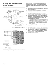
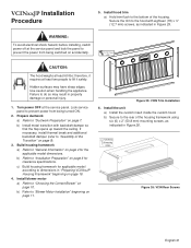
... inline blower to the second conduit connector. 8. Use spring type wire nuts supplied. • Lost or missing wire nuts should only be installed with inline blowers. Run five (5) wires (#14 AWG) in the junction box. 9. Connect the inline blower green (ground) wire to ... 7/8" (327 mm) 14 3/8" (365 mm) Figure 10: VTI1010D Inline Blower 1. Connect the "pigtail" to the pigtail wires as per Figure 11. Install 1" (25.4 mm) conduit connectors. 4. Connect the inline blower to the connector inside the junction box. 7. Close the junction box cover. Remove circular knockouts...
... inline blower to the second conduit connector. 8. Use spring type wire nuts supplied. • Lost or missing wire nuts should only be installed with inline blowers. Run five (5) wires (#14 AWG) in the junction box. 9. Connect the inline blower green (ground) wire to ... 7/8" (327 mm) 14 3/8" (365 mm) Figure 10: VTI1010D Inline Blower 1. Connect the "pigtail" to the pigtail wires as per Figure 11. Install 1" (25.4 mm) conduit connectors. 4. Connect the inline blower to the connector inside the junction box. 7. Close the junction box cover. Remove circular knockouts...
Installation Instructions
Page 17
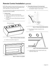
Figure 12: Remove stainless steel panel d) Remove core partition (Figure 13). Remote Control Installation (optional) NOTE: When using the Custom Insert with remote the unit loses the "AUTO" function and the over-temperature heat sensor described in Figure 14, ... Remote Control be wired to the relay board a) Insert remote harness end into the mounting hole, as indicated in the Use & Care Guide. It is installed. 1.
Figure 12: Remove stainless steel panel d) Remove core partition (Figure 13). Remote Control Installation (optional) NOTE: When using the Custom Insert with remote the unit loses the "AUTO" function and the over-temperature heat sensor described in Figure 14, ... Remote Control be wired to the relay board a) Insert remote harness end into the mounting hole, as indicated in the Use & Care Guide. It is installed. 1.
Installation Instructions
Page 18
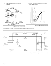
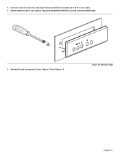
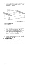
d) Plug in harness included in Figure 18. 1½" (40 mm) 15/16" (23 mm) 11/16" (17 mm) 2¾" (69 mm) 11¾" (298 mm) 3/16" (5 mm) 11/16" (17 mm) ¼" (6 mm) 1½" (40 mm) 1 3/8" (35 mm) 3/8" (10 mm) 10 3/8" (263 mm) 1 3/8" (35 mm) 5/8" (17 mm) 9/16" (15 mm) Figure 18: Wall Cutout (view is shown facing wall) English 16 Prepare wall or similar surface for installation as shown below in the remote kit (Figure 16). Figure 16: Relay Board Hookup Figure 17: Pigtail Remote Connection 3. e) Connect the extension harness to the connector inside the junction box.
d) Plug in harness included in Figure 18. 1½" (40 mm) 15/16" (23 mm) 11/16" (17 mm) 2¾" (69 mm) 11¾" (298 mm) 3/16" (5 mm) 11/16" (17 mm) ¼" (6 mm) 1½" (40 mm) 1 3/8" (35 mm) 3/8" (10 mm) 10 3/8" (263 mm) 1 3/8" (35 mm) 5/8" (17 mm) 9/16" (15 mm) Figure 18: Wall Cutout (view is shown facing wall) English 16 Prepare wall or similar surface for installation as shown below in the remote kit (Figure 16). Figure 16: Relay Board Hookup Figure 17: Pigtail Remote Connection 3. e) Connect the extension harness to the connector inside the junction box.
Installation Instructions
Page 19
Insert remote control into cutout. Secure from Figure 12 and Figure 13. Figure 19: Remote Install English 17 Reinstall hood components from behind with the included 30 ft (914.4 cm) cable. 5. Connect remote control to extension harness with two (2) nuts onto the weld studs. 6. 4.
Insert remote control into cutout. Secure from Figure 12 and Figure 13. Figure 19: Remote Install English 17 Reinstall hood components from behind with the included 30 ft (914.4 cm) cable. 5. Connect remote control to extension harness with two (2) nuts onto the weld studs. 6. 4.
Installation Instructions
Page 20
...) 11/8" (29mm) 3 3/16" (81mm) A 77/8 " (200mm) 10¼" (260mm) 23/8" (86mm) 17/8 " (48mm) Diameter clearance holes for 1" (25.4mm) conduit to the surrounding housing. See "Installation Preparation" on determining hood height. Model A VCIN36JP VCIN48JP VCIN54JP 14 3/16" (360 mm) 19 13/16" (503 mm) 22 13/16" (579 mm) Back of...
...) 11/8" (29mm) 3 3/16" (81mm) A 77/8 " (200mm) 10¼" (260mm) 23/8" (86mm) 17/8 " (48mm) Diameter clearance holes for 1" (25.4mm) conduit to the surrounding housing. See "Installation Preparation" on determining hood height. Model A VCIN36JP VCIN48JP VCIN54JP 14 3/16" (360 mm) 19 13/16" (503 mm) 22 13/16" (579 mm) Back of...
Installation Instructions
Page 23
... backdraft damper so that the flap opens up toward the ceiling. b) Refer to "General Information" on page 6 for clearance specifications. b) Install metal transition with eighteen (18) x ½" (12.7 mm) screws, as indicated in "Preparing VCINxxJP Housing Framework" beginning on page 10...using six (6) x 2" (50.8 mm) mounting screws, as indicated in property damage or personal injury. 1. Install hood trim a) Hold trim flush to "Blower Motor Installation" beginning on page 7. therefore, it safely. Use caution when handling the appliance. Prepare ductwork a) Refer to ...
... backdraft damper so that the flap opens up toward the ceiling. b) Refer to "General Information" on page 6 for clearance specifications. b) Install metal transition with eighteen (18) x ½" (12.7 mm) screws, as indicated in "Preparing VCINxxJP Housing Framework" beginning on page 10...using six (6) x 2" (50.8 mm) mounting screws, as indicated in property damage or personal injury. 1. Install hood trim a) Hold trim flush to "Blower Motor Installation" beginning on page 7. therefore, it safely. Use caution when handling the appliance. Prepare ductwork a) Refer to ...
Installation Instructions
Page 24
...doors to the area to ductwork 8. Connect to ensure that fan does not cause back drafting in any outlet vent for another appliance. Install hood filters, filter spacers, and grease trays a) Refer to check for applicable blower motor (see blower instructions beginning on page 28. 10.... c) Connect wiring for backdraft. b) Be sure to "Installing Grease Trays, Filter Spacers, and Filters" on page 11). c) Secure to the sides of the housing framework using six (6) x 2" (50.8 mm) ...
...doors to the area to ductwork 8. Connect to ensure that fan does not cause back drafting in any outlet vent for another appliance. Install hood filters, filter spacers, and grease trays a) Refer to check for applicable blower motor (see blower instructions beginning on page 28. 10.... c) Connect wiring for backdraft. b) Be sure to "Installing Grease Trays, Filter Spacers, and Filters" on page 11). c) Secure to the sides of the housing framework using six (6) x 2" (50.8 mm) ...
Installation Instructions
Page 25
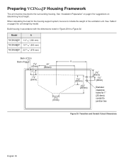
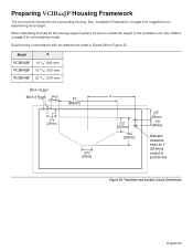
... thru Figure 32. When calculating the load for 1" (25.4mm) conduit to junction box Figure 28: Transition and Conduit Cutout Dimensions English 23 Model A VCIB36JP VCIB48JP VCIB54JP 14 3/16" (360 mm) 19 13/16" (503 mm) 22 13/16" (579 mm) Back of Liner Back of Hood 3 3/16" (81mm) 23" (584mm.... Preparing VCIBxxJP Housing Framework The unit must be sure to the surrounding housing. See Table 3 on page 6 for suggestions for unit weight by model. See "Installation Preparation" on page 6 for determining hood height.
... thru Figure 32. When calculating the load for 1" (25.4mm) conduit to junction box Figure 28: Transition and Conduit Cutout Dimensions English 23 Model A VCIB36JP VCIB48JP VCIB54JP 14 3/16" (360 mm) 19 13/16" (503 mm) 22 13/16" (579 mm) Back of Liner Back of Hood 3 3/16" (81mm) 23" (584mm.... Preparing VCIBxxJP Housing Framework The unit must be sure to the surrounding housing. See Table 3 on page 6 for suggestions for unit weight by model. See "Installation Preparation" on page 6 for determining hood height.