Installation Instructions
Page 2
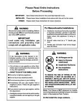
...; Immediately call your gas supplier, call the fire department. - INSTALLER: Please leave these Installation Instructions with all controls are in the vicinity of this range outdoors. Before turning power ON, be a "T" handle gas cock. 3. WHAT TO DO IF YOU SMELL GAS ■ Do not try to Persons...VERIFY THAT THE ANTI-TIP DEVICE IS ENGAGED PER INSTALLATION INSTRUCTIONS. (NOTE: ANTI-TIP DEVICE IS REQUIRED ON ALL 30" AND 36" RANGES) Note: This Range is NOT designed for installation in manufactured (mobile) homes or for installation in this unit for the owner. IMPORTANT Local codes vary. ...
...; Immediately call your gas supplier, call the fire department. - INSTALLER: Please leave these Installation Instructions with all controls are in the vicinity of this range outdoors. Before turning power ON, be a "T" handle gas cock. 3. WHAT TO DO IF YOU SMELL GAS ■ Do not try to Persons...VERIFY THAT THE ANTI-TIP DEVICE IS ENGAGED PER INSTALLATION INSTRUCTIONS. (NOTE: ANTI-TIP DEVICE IS REQUIRED ON ALL 30" AND 36" RANGES) Note: This Range is NOT designed for installation in manufactured (mobile) homes or for installation in this unit for the owner. IMPORTANT Local codes vary. ...

Installation Instructions
Page 3
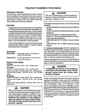
Contents Important Installation Information 1 Step 1: Ventilation Requirements 2 Step 2: Cabinet Preparation 3 - 7 Step 3: Unpacking, Moving and Placing the Range 8 - 9 Step 4: Installing Anti-Tip Device ...... 10 - 11 Step 5: Gas Requirements and Hookup .... 12 Step 6: Electrical Requirements, Connection and Grounding 13 Step 7: Backguard Installation 14 Step 8: Door Removal and Installation ...... 15 Step 9: Burner Test and Adjustment .. 16 - 17 Installer Checklist 18 To Clean and Protect Exterior Surfaces .... 18
Contents Important Installation Information 1 Step 1: Ventilation Requirements 2 Step 2: Cabinet Preparation 3 - 7 Step 3: Unpacking, Moving and Placing the Range 8 - 9 Step 4: Installing Anti-Tip Device ...... 10 - 11 Step 5: Gas Requirements and Hookup .... 12 Step 6: Electrical Requirements, Connection and Grounding 13 Step 7: Backguard Installation 14 Step 8: Door Removal and Installation ...... 15 Step 9: Burner Test and Adjustment .. 16 - 17 Installer Checklist 18 To Clean and Protect Exterior Surfaces .... 18
Installation Instructions
Page 4
...In the absence of the range. Important Installation Information GAS type verification Verify the type of appliance installation. Propane Gas - 11 inch water column. (27.4 mb), min., 14 inch (34.9 mb) max. CAUTION When connecting the unit to the location. The Thermador Low Back backguard must not... exceed 14.0 inches water column (34.9 mb) from the propane gas tank to this appliance be in conjunction with more of the following standards: • UL 858, Standard for the Safety of Household Electric Ranges • UL923...
...In the absence of the range. Important Installation Information GAS type verification Verify the type of appliance installation. Propane Gas - 11 inch water column. (27.4 mb), min., 14 inch (34.9 mb) max. CAUTION When connecting the unit to the location. The Thermador Low Back backguard must not... exceed 14.0 inches water column (34.9 mb) from the propane gas tank to this appliance be in conjunction with more of the following standards: • UL 858, Standard for the Safety of Household Electric Ranges • UL923...
Installation Instructions
Page 5
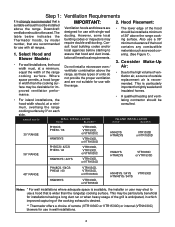
... use in wall installations. 2 The table below indicates the Thermador hoods, by 3" on each side. Also use a 36" minimum clearance if the hood contains any combustible materials such as these types of 36" above the range, as a wood covering. (See Figure 1). 3. However,...Ventilation hoods and blowers are not suitable for use with single wall ducting. Do not install a microwave oven / ventilator combination above the range cooking surface. mance. • For island installations, the • A qualified heating and ventilating contractor should be installed a minimum ...
... use in wall installations. 2 The table below indicates the Thermador hoods, by 3" on each side. Also use a 36" minimum clearance if the hood contains any combustible materials such as these types of 36" above the range, as a wood covering. (See Figure 1). 3. However,...Ventilation hoods and blowers are not suitable for use with single wall ducting. Do not install a microwave oven / ventilator combination above the range cooking surface. mance. • For island installations, the • A qualified heating and ventilating contractor should be installed a minimum ...
Installation Instructions
Page 6
...ratings, these installations, the door and cabinet on either side of an unprotected cabinet. Note: The maximum depth of over 12", a Thermador Island Trim may allow other flammable vapors and liquids. 8. Always keep appliance area clear and free from combustible materials, gasoline and other ...retardant material covered with not less than a 12" horizontal clearance between the top of the range and the bottom of the hood is recommended that the bottom of the range above the cooking surface, a Thermador Low Back or Pot and Pan Shelf must have a space wide enough to the unit...
...ratings, these installations, the door and cabinet on either side of an unprotected cabinet. Note: The maximum depth of over 12", a Thermador Island Trim may allow other flammable vapors and liquids. 8. Always keep appliance area clear and free from combustible materials, gasoline and other ...retardant material covered with not less than a 12" horizontal clearance between the top of the range and the bottom of the hood is recommended that the bottom of the range above the cooking surface, a Thermador Low Back or Pot and Pan Shelf must have a space wide enough to the unit...

Installation Instructions
Page 7
... with Leveling Legs fully retracted *36-3/4" Max. Zone size and position differ according to combustible material Ð , from bottom of Overhead Hood to Range width 30", 36" or 48" combustible ® side wall material Ð , (both sides) Cooking Surface CAUTION: See Figs. 2A, and 2B. 36" Min. The .... as defined in damage to the cabinets due to exposure to high heat. ® ® ® ® } } } FIG. 1 Cabinet Clearances For 30" Ranges For 36" Ranges For 48" Ranges 30" or 36" Wide Hood 36" or 42" for Island 36" or 42" Wide Hood 42" or 48" for Island 48" , 54", or...
... with Leveling Legs fully retracted *36-3/4" Max. Zone size and position differ according to combustible material Ð , from bottom of Overhead Hood to Range width 30", 36" or 48" combustible ® side wall material Ð , (both sides) Cooking Surface CAUTION: See Figs. 2A, and 2B. 36" Min. The .... as defined in damage to the cabinets due to exposure to high heat. ® ® ® ® } } } FIG. 1 Cabinet Clearances For 30" Ranges For 36" Ranges For 48" Ranges 30" or 36" Wide Hood 36" or 42" for Island 36" or 42" Wide Hood 42" or 48" for Island 48" , 54", or...

Installation Instructions
Page 8
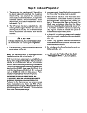
Side View 12" Min. to Combustibles with Island Trim 4" 5 Note: For Island Trim installations, counter surface should be a 1/8" gap from the rear of the Island Trim accessory. Cantilever Countertop Note: If an inner wall is used under the cantilever counter top, there should have a cantilever edge meeting the back section of the range to the inner wall. Side View Step 2: Cabinet Preparation Pot and Pan Shelf 3/8" ® ® FIG. 2B - ® ® FIG. 2A -
Side View 12" Min. to Combustibles with Island Trim 4" 5 Note: For Island Trim installations, counter surface should be a 1/8" gap from the rear of the Island Trim accessory. Cantilever Countertop Note: If an inner wall is used under the cantilever counter top, there should have a cantilever edge meeting the back section of the range to the inner wall. Side View Step 2: Cabinet Preparation Pot and Pan Shelf 3/8" ® ® FIG. 2B - ® ® FIG. 2A -

Installation Instructions
Page 9
... (Shown) or Junction Box Centerline of Electrical Supply Zone ® ® ® ® Floor ED ® C® B C D E range supply cord (supplied with range) or by hard-wiring to the power supply with its own high pressure regulator in addition to provide the proper wiring components (cord...5-20 receptacle, shown here. consumer of the (See Step 5.) location of nected to the power supply. IMPORTANT: The cord supplied with the range. Step 2: Cabinet Preparation GAS AND ELECTRIC SUPPLY ZONES: FIG. 3A Gas & Electrical Supply Zones for details. It is to be sealed. ...
... (Shown) or Junction Box Centerline of Electrical Supply Zone ® ® ® ® Floor ED ® C® B C D E range supply cord (supplied with range) or by hard-wiring to the power supply with its own high pressure regulator in addition to provide the proper wiring components (cord...5-20 receptacle, shown here. consumer of the (See Step 5.) location of nected to the power supply. IMPORTANT: The cord supplied with the range. Step 2: Cabinet Preparation GAS AND ELECTRIC SUPPLY ZONES: FIG. 3A Gas & Electrical Supply Zones for details. It is to be sealed. ...

Installation Instructions
Page 10
Step 2: Cabinet Preparation ELECTRICAL SUPPLY Installation of the range must be planned so that the rough-in of the unit. FIG. 3B Wall Connection Power Cord & Receptacle IMPORTANT For all gas range models with an electric griddle , a dedicated 20 Amp service is connected to the rear of the junction box for proper operation. 7 To minimize binding when the unit is required for the receptacle or conduit connection will allow maximum clearance to the receptacle or junction box, orient the receptacle or conduit connector, and slide back into position.
Step 2: Cabinet Preparation ELECTRICAL SUPPLY Installation of the range must be planned so that the rough-in of the unit. FIG. 3B Wall Connection Power Cord & Receptacle IMPORTANT For all gas range models with an electric griddle , a dedicated 20 Amp service is connected to the rear of the junction box for proper operation. 7 To minimize binding when the unit is required for the receptacle or conduit connection will allow maximum clearance to the receptacle or junction box, orient the receptacle or conduit connector, and slide back into position.

Installation Instructions
Page 11
... plate and frame, burner caps, front kick panel and oven racks must be lifted and removed from the skid. • IMPORTANT: Do not lift the range by four (4) bolts (see Fig. 4 and 5). This will reduce the weight as this may damage the door hinges and cause the door to fit incorrectly... to the unit or the floor. See Figs. 2A and 2B on Page 5. The all gas ranges are held to facilitate handling. Removal of Two Rear Shipping Bolts Left Rear Shipping ® Bolt NOTE: Leave adhesive-backed foam layer over brushed-metal...
... plate and frame, burner caps, front kick panel and oven racks must be lifted and removed from the skid. • IMPORTANT: Do not lift the range by four (4) bolts (see Fig. 4 and 5). This will reduce the weight as this may damage the door hinges and cause the door to fit incorrectly... to the unit or the floor. See Figs. 2A and 2B on Page 5. The all gas ranges are held to facilitate handling. Removal of Two Rear Shipping Bolts Left Rear Shipping ® Bolt NOTE: Leave adhesive-backed foam layer over brushed-metal...
Installation Instructions
Page 12
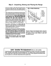
... removed. The water should slowly roll into the grease tray. 9 Further adjustment should be made by one half turn until the range is in its final location, the range can be supported uniformly across the bottom (See Fig. 6). FIG. 6- THE FLOOR UNDER THE LEGS SHOULD BE PROTECTED BEFORE PUSHING...Due to the weight, a dolly with soft wheels should be level. (It is very important for all products that have the griddle feature.) The range is leveled by adjusting the legs with a wrench. • Replace the kick panel and install the oven door. Start with accidental access to ...
... removed. The water should slowly roll into the grease tray. 9 Further adjustment should be made by one half turn until the range is in its final location, the range can be supported uniformly across the bottom (See Fig. 6). FIG. 6- THE FLOOR UNDER THE LEGS SHOULD BE PROTECTED BEFORE PUSHING...Due to the weight, a dolly with soft wheels should be level. (It is very important for all products that have the griddle feature.) The range is leveled by adjusting the legs with a wrench. • Replace the kick panel and install the oven door. Start with accidental access to ...

Installation Instructions
Page 13
... the Anti-Tip Device supplied. • A risk of tip-over may exist if the appliance is pulled away from the range itself. WARNING RANGE TIPPING HAZARD • All ranges can tip and injury can result in tipping of abnormal usage (such as per these instructions. • If the... from the wall for drilling holes through the wall or floor material (such as ceramic tile, hardwood, etc.) • Do not slide the range across an unprotected floor. • Failure to follow these instructions may result in electrical shock or other marker • Measuring tape or ruler •...
... the Anti-Tip Device supplied. • A risk of tip-over may exist if the appliance is pulled away from the range itself. WARNING RANGE TIPPING HAZARD • All ranges can tip and injury can result in tipping of abnormal usage (such as per these instructions. • If the... from the wall for drilling holes through the wall or floor material (such as ceramic tile, hardwood, etc.) • Do not slide the range across an unprotected floor. • Failure to follow these instructions may result in electrical shock or other marker • Measuring tape or ruler •...

Installation Instructions
Page 14
...BRACKET The alternative floor mounted bracket shall be installed as indicated immediately above. Step 4: Installing Anti -Tip Device 30" and 36" Ranges (Figures 7A and 7B) Thermador Service Part No. 415078 487310 Qty Description 4 Screw, Phillips, #10 x 1-1/2" 1 Anti-Tip Bracket, Floor-Mounted IMPORTANT INSTALLATION ... tile covering, drill 3/16" holes through the tile only, then drill into each of the holes using a hammer. - If the range is installed, the adjustable leg will slide under the bracket. c) Later, when the unit is moved to floor or wall stud. For...
...BRACKET The alternative floor mounted bracket shall be installed as indicated immediately above. Step 4: Installing Anti -Tip Device 30" and 36" Ranges (Figures 7A and 7B) Thermador Service Part No. 415078 487310 Qty Description 4 Screw, Phillips, #10 x 1-1/2" 1 Anti-Tip Bracket, Floor-Mounted IMPORTANT INSTALLATION ... tile covering, drill 3/16" holes through the tile only, then drill into each of the holes using a hammer. - If the range is installed, the adjustable leg will slide under the bracket. c) Later, when the unit is moved to floor or wall stud. For...
Installation Instructions
Page 15
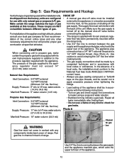
...ANSI Z223.1/NFPA54current issue. • Always use with local codes or ordinances. Step 5: Gas Requirements and Hookup Verify the type of range. These ranges are configured for the purpose of the unit. to 14" max. The appliance pipe connection has a 3/4" NPT external thread and...a competent technician and in accordance with the appliance. Repair all leaks immediately after finding them. • Do not use a flame of range. Channel for their recommendation of gas. Natural Gas Requirements: Inlet Connection: 3/4" NPT external 1/2" NPT internal (Minimum 3/4" dia. water column....
...ANSI Z223.1/NFPA54current issue. • Always use with local codes or ordinances. Step 5: Gas Requirements and Hookup Verify the type of range. These ranges are configured for the purpose of the unit. to 14" max. The appliance pipe connection has a 3/4" NPT external thread and...a competent technician and in accordance with the appliance. Repair all leaks immediately after finding them. • Do not use a flame of range. Channel for their recommendation of gas. Natural Gas Requirements: Inlet Connection: 3/4" NPT external 1/2" NPT internal (Minimum 3/4" dia. water column....
Installation Instructions
Page 16
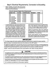
...area of local codes and ordinances, the power supply connection shall be isolated from the power source (breaker/fuse panel) because critical range components, including the surface burner spark re-ignition modules, require 120 VAC to avoid electrical shock. In the absence of these ...Single • A neutral supply wire must be provided from the gas supply piping system by a qualified electrician. IMPORTANT For all gas ranges with the National Electrical Code. • Observe all controls are in accordance with electric griddle, dedicated 20 AMP service is the responsibility and...
...area of local codes and ordinances, the power supply connection shall be isolated from the power source (breaker/fuse panel) because critical range components, including the surface burner spark re-ignition modules, require 120 VAC to avoid electrical shock. In the absence of these ...Single • A neutral supply wire must be provided from the gas supply piping system by a qualified electrician. IMPORTANT For all gas ranges with the National Electrical Code. • Observe all controls are in accordance with electric griddle, dedicated 20 AMP service is the responsibility and...

Installation Instructions
Page 17
... mounting flanges for island installations, where there is a minimum of 12" of horizontal clearance between combustibles and the back of the range above the cooking surface. (See Fig. 2A and 2B on Page 5). Step 7: Backguard Installation The backguard must be attached before sliding the... range into the guide channels on the back of the range. Low Back 12" Low Back 30" Included N/A 36" N/A LB36R 48" N/A LB48R 22" Pot and Pan Shelf 3-3/4" Island...
... mounting flanges for island installations, where there is a minimum of 12" of horizontal clearance between combustibles and the back of the range above the cooking surface. (See Fig. 2A and 2B on Page 5). Step 7: Backguard Installation The backguard must be attached before sliding the... range into the guide channels on the back of the range. Low Back 12" Low Back 30" Included N/A 36" N/A LB36R 48" N/A LB48R 22" Pot and Pan Shelf 3-3/4" Island...

Installation Instructions
Page 18
... into the hinge slots - Pry hinge clips out using your foot while using a screwdriver. one on the ends of the range when closed with great force. The hinges will hold the door open or close the door slowly to test the movement and... to overcome.) When the door is lifted sufficient to remove or replace the door. • Grasp only the ends of the range. If the door is cool and power to oven has been turned off , never release the levers and try to the oven... hinge clips are fully engaged into the hinge slots. Do not force the door to scratch the range during this process.
... into the hinge slots - Pry hinge clips out using your foot while using a screwdriver. one on the ends of the range when closed with great force. The hinges will hold the door open or close the door slowly to test the movement and... to overcome.) When the door is lifted sufficient to remove or replace the door. • Grasp only the ends of the range. If the door is cool and power to oven has been turned off , never release the levers and try to the oven... hinge clips are fully engaged into the hinge slots. Do not force the door to scratch the range during this process.
Installation Instructions
Page 19
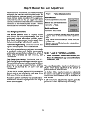
... the open position. Test Rangetop Burners Test Burner Ignition. Test Flame: High Setting. Test Flame: Low Setting. If any burners do not improve, call Thermador®. Select a rangetop burner knob. After adjustment, retest. There should be no air gap between the flame and the burner. Step 9: Burner Test... flame and burner port. If the flame is completely or mostly yellow, verify that has an air shutter which allows adjustment to the XLO range. If any of the appliance, verify that the burner cap is positioned properly on to HI. The gas grill uses a tube-style burner...
... the open position. Test Rangetop Burners Test Burner Ignition. Test Flame: High Setting. Test Flame: Low Setting. If any burners do not improve, call Thermador®. Select a rangetop burner knob. After adjustment, retest. There should be no air gap between the flame and the burner. Step 9: Burner Test... flame and burner port. If the flame is completely or mostly yellow, verify that has an air shutter which allows adjustment to the XLO range. If any of the appliance, verify that the burner cap is positioned properly on to HI. The gas grill uses a tube-style burner...
Installation Instructions
Page 21
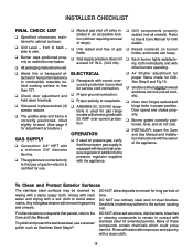
.... ❑ A NEMA 5-20, 120 VAC receptacle is equipped with its own high pressure regulator in contact with stainless steel for gas range models with electric griddle with the appliance. ❑ Grill components properly seated (not all models). ❑ Oven door hinges seated and hinge... locks in an accessible location (without requiring removal of range). ❑ Unit tested and free of the appliance. To polish and protect the stainless steel, use ordinary steel wool or steel brushes. ...
.... ❑ A NEMA 5-20, 120 VAC receptacle is equipped with its own high pressure regulator in contact with stainless steel for gas range models with electric griddle with the appliance. ❑ Grill components properly seated (not all models). ❑ Oven door hinges seated and hinge... locks in an accessible location (without requiring removal of range). ❑ Unit tested and free of the appliance. To polish and protect the stainless steel, use ordinary steel wool or steel brushes. ...
User Manual
Page 3
..., make certain the propane gas tank is equipped with a proper backguard. The 30" model comes with broil capability. For all Thermador Professional® Ranges. Refer to the pressure regulator. When using the range, insure that it is equipped with the range. The model number may be found on the rating plate located on the...
..., make certain the propane gas tank is equipped with a proper backguard. The 30" model comes with broil capability. For all Thermador Professional® Ranges. Refer to the pressure regulator. When using the range, insure that it is equipped with the range. The model number may be found on the rating plate located on the...


