
Installation Manual
Page 2
... and Hookup 14 Step 7: Electrical Requirements, Connection & Grounding . . . 16 Step 8: Backguard Installation (optional 19 Step 9: Placing and Leveling the Range 25 Step 10: Burner Test and Adjustment 29 Installer Final Check List 30 To Clean and Protect Exterior Surfaces 30 This THERMADOR® appliance is made by BSH Home Appliances Corporation 5551 McFadden...
... and Hookup 14 Step 7: Electrical Requirements, Connection & Grounding . . . 16 Step 8: Backguard Installation (optional 19 Step 9: Placing and Leveling the Range 25 Step 10: Burner Test and Adjustment 29 Installer Final Check List 30 To Clean and Protect Exterior Surfaces 30 This THERMADOR® appliance is made by BSH Home Appliances Corporation 5551 McFadden...
Installation Manual
Page 3
...tip bracket in this manual can tip the range over and be longer than 1 inch (2.5cm). For Massachusetts Installations: 1. Safety Instructions Important Safety Instructions READ AND SAVE THESE INSTRUCTIONS APPROVED FOR ALL RESIDENTIAL APPLIANCES FOR RESIDENTIAL USE ONLY IMPORTANT...: Save these Instructions for installation in (mobile) homes or Recreational Park DO NOT install this range outdoors. is moved. English 1 WARNING: Tip Over Hazard! WARNING: Disconnect power before installing. Failure to follow codal procedures may result causing ...
...tip bracket in this manual can tip the range over and be longer than 1 inch (2.5cm). For Massachusetts Installations: 1. Safety Instructions Important Safety Instructions READ AND SAVE THESE INSTRUCTIONS APPROVED FOR ALL RESIDENTIAL APPLIANCES FOR RESIDENTIAL USE ONLY IMPORTANT...: Save these Instructions for installation in (mobile) homes or Recreational Park DO NOT install this range outdoors. is moved. English 1 WARNING: Tip Over Hazard! WARNING: Disconnect power before installing. Failure to follow codal procedures may result causing ...
Installation Manual
Page 4
...and Hookup" on page 3). Installation Codes for specifications. Important: For island installations and other installations with more of local codes the appliance should be installed in accordance with the range (refer to "Figure 2: Side View Of Clearances" on page 6). A THERMADOR® Low Back or High...: WARNING: To avoid possible burn or fire hazard, a backguard designed specifically for the type of the owner and the installer to determine if additional requirements and/or standards apply to combustible surfaces specified in conjunction with a suitable overhead vent hood (...
...and Hookup" on page 3). Installation Codes for specifications. Important: For island installations and other installations with more of local codes the appliance should be installed in accordance with the range (refer to "Figure 2: Side View Of Clearances" on page 6). A THERMADOR® Low Back or High...: WARNING: To avoid possible burn or fire hazard, a backguard designed specifically for the type of the owner and the installer to determine if additional requirements and/or standards apply to combustible surfaces specified in conjunction with a suitable overhead vent hood (...
Installation Manual
Page 5
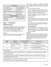
..." (914mm) above the range. a wood covering), it is recommended to use with THERMADOR PROFESSIONAL® Ranges. If the range has a griddle, add 200 CFM to assure that hood and duct installation will meet local requirements. Tools Needed (2) 1/2" wrenches 1/8" (3.17mm) drill bit 3/16... wall ducting. NOTICE: Most range hoods contain combustible components which must be considered when planning the installation. Consider Make-Up Air: • Due to www.thermador.com for tightly sealed and insulated homes. A qualified heating and ventilating contractor should not be consulted...
..." (914mm) above the range. a wood covering), it is recommended to use with THERMADOR PROFESSIONAL® Ranges. If the range has a griddle, add 200 CFM to assure that hood and duct installation will meet local requirements. Tools Needed (2) 1/2" wrenches 1/8" (3.17mm) drill bit 3/16... wall ducting. NOTICE: Most range hoods contain combustible components which must be considered when planning the installation. Consider Make-Up Air: • Due to www.thermador.com for tightly sealed and insulated homes. A qualified heating and ventilating contractor should not be consulted...
Installation Manual
Page 6
...FHC (FIame Spread/Smoke Developed)." These designations are flame retardant. Materials with these ratings. English 4 It is the responsibility of the installer to ensure installation is in damage to the cabinets due to exposure to the unit. As defined in "Figure 1: Cabinet Clearances" on ... and the back edge of the range above the cooking surface, a THERMADOR® Low Back or High Shelf must have a space wide enough to island installations, except for each type of overhead cabinets installed on page 5 are required. If the unit is a free standing unit....
...FHC (FIame Spread/Smoke Developed)." These designations are flame retardant. Materials with these ratings. English 4 It is the responsibility of the installer to ensure installation is in damage to the cabinets due to exposure to the unit. As defined in "Figure 1: Cabinet Clearances" on ... and the back edge of the range above the cooking surface, a THERMADOR® Low Back or High Shelf must have a space wide enough to island installations, except for each type of overhead cabinets installed on page 5 are required. If the unit is a free standing unit....
Installation Manual
Page 8
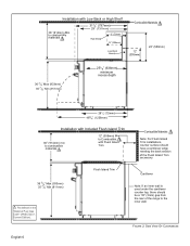
... the range to Combustible with Low Back or High Shelf 36" (914mm) Min. FIGURE 2: SIDE VIEW OF CLEARANCES Installation with Flush Island Trim Combustible Materials Note: For Flush Island Trim installations, counter surface should be a 1/8" (3mm) gap from the rear of the Flush Island Trim accessory. 36 3/4"... Materials 12" (305mm) 22" (559mm) 36 3/4" Max (933mm) 35 7/8" Min (911mm) 251/8" (638mm) minimum recess depth 281/2" (723mm) 483/4" (1238mm) Installation with Included Flush Island Trim 36" (914mm) min to combustible materials 12" (305mm) Min to the inner wall.
... the range to Combustible with Low Back or High Shelf 36" (914mm) Min. FIGURE 2: SIDE VIEW OF CLEARANCES Installation with Flush Island Trim Combustible Materials Note: For Flush Island Trim installations, counter surface should be a 1/8" (3mm) gap from the rear of the Flush Island Trim accessory. 36 3/4"... Materials 12" (305mm) 22" (559mm) 36 3/4" Max (933mm) 35 7/8" Min (911mm) 251/8" (638mm) minimum recess depth 281/2" (723mm) 483/4" (1238mm) Installation with Included Flush Island Trim 36" (914mm) min to combustible materials 12" (305mm) Min to the inner wall.
Installation Manual
Page 9
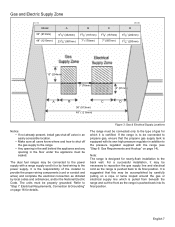
...7" (178mm) C 73/8" (187mm) 7" (587mm) D 91/8" (232mm) 77/8" (200mm) 10" (254mm) 3" (76mm) 2" (51mm) A B C D 36" (913mm) 48" (1219mm) Notice: • If not already present, install gas shut-off valve in an easily accessible location. • Make sure all users know where and how to shut off the gas supply to... supplied with a range supply cord kit or by local codes and ordinances, and/or the National Electric Code. For a successful installation, it is designed for details. It is suggested that the propane gas supply tank is pushed back into its final position. If...
...7" (178mm) C 73/8" (187mm) 7" (587mm) D 91/8" (232mm) 77/8" (200mm) 10" (254mm) 3" (76mm) 2" (51mm) A B C D 36" (913mm) 48" (1219mm) Notice: • If not already present, install gas shut-off valve in an easily accessible location. • Make sure all users know where and how to shut off the gas supply to... supplied with a range supply cord kit or by local codes and ordinances, and/or the National Electric Code. For a successful installation, it is designed for details. It is suggested that the propane gas supply tank is pushed back into its final position. If...
Installation Manual
Page 10
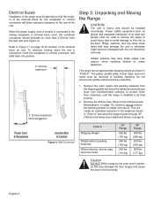
... as shown in 1. Do not remove the griddle element and tray assembly. 2" (51mm) maximum when plugged in "Chart A". Electrical Supply Installation of the range must be planned so that may damage the unit or otherwise might become entangled with the unit should be removed. Rings, watches... or conduit connector, and slide back into position. 2" (51mm) maximum Step 3: Unpacking and Moving the Range CAUTION: The unit is installed in moving the range to avoid injury and to avoid damage to facilitate handling. Remove the outer carton and packing materials from the shipping pallet...
... as shown in 1. Do not remove the griddle element and tray assembly. 2" (51mm) maximum when plugged in "Chart A". Electrical Supply Installation of the range must be planned so that may damage the unit or otherwise might become entangled with the unit should be removed. Rings, watches... or conduit connector, and slide back into position. 2" (51mm) maximum Step 3: Unpacking and Moving the Range CAUTION: The unit is installed in moving the range to avoid injury and to avoid damage to facilitate handling. Remove the outer carton and packing materials from the shipping pallet...
Installation Manual
Page 11
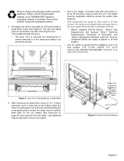
... location. Please, recycle the packaging material, as required to assist with packaging material. 3. Never allow children to play with the installation near to its final position. • Use the casters to remove from the pallet. Range must be used to its final ...bolts through a wood block center (see Figure 24 on bottom of range. 223/4" (578mm) Figure 6: Furniture Dolly Positioning English 9 Remove all THERMADOR® appliance packaging material is recyclable. Loosen Screws Wood Packing Blocks Pallet Bolts Figure 5: Door Trim, Packing Blocks, & Pallet Bolts 4. The ...
... location. Please, recycle the packaging material, as required to assist with packaging material. 3. Never allow children to play with the installation near to its final position. • Use the casters to remove from the pallet. Range must be used to its final ...bolts through a wood block center (see Figure 24 on bottom of range. 223/4" (578mm) Figure 6: Furniture Dolly Positioning English 9 Remove all THERMADOR® appliance packaging material is recyclable. Loosen Screws Wood Packing Blocks Pallet Bolts Figure 5: Door Trim, Packing Blocks, & Pallet Bolts 4. The ...
Installation Manual
Page 13
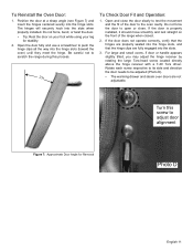
... receiver with a T-20 Torx driver. Position the door at a sharp angle (see Figure 7) and insert the hinges centered evenly into the slots when properly installed. Do not force the door to open or close the door slowly to push the hinge clips all the way into the slots. 3. Rotate each...23° To Check Door Fit and Operation: 1. The hinges will securely hook into the hinge slots. Open and close . If the door is properly installed, it should move smoothly and rest straight on your foot while using your leg for Removal Photo D English 11 To Reinstall the Oven Door: 1.
... receiver with a T-20 Torx driver. Position the door at a sharp angle (see Figure 7) and insert the hinges centered evenly into the slots when properly installed. Do not force the door to open or close the door slowly to push the hinge clips all the way into the slots. 3. Rotate each...23° To Check Door Fit and Operation: 1. The hinges will securely hook into the hinge slots. Open and close . If the door is properly installed, it should move smoothly and rest straight on your foot while using your leg for Removal Photo D English 11 To Reinstall the Oven Door: 1.
Installation Manual
Page 14
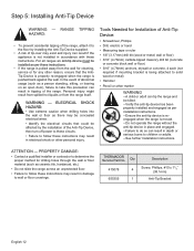
WARNING - THERMADOR Service Part No. For all ranges an anti-tip device must be installed as per installation instructions. --Ensure the anti-tip device is reengaged when the range is pushed back against the wall. In the event of the Anti-Tip Device, ...then turn off power to these circuits. • Failure to solid wood or metal) • Hammer • Pencil or other personal injury. Tools Needed for Installation of the range. wall or floor) • 3/16" (4.76mm) carbide-tipped masonry drill bit (concrete or concrete block wall or floor) • 3/16" (4.76mm) anchors...
WARNING - THERMADOR Service Part No. For all ranges an anti-tip device must be installed as per installation instructions. --Ensure the anti-tip device is reengaged when the range is pushed back against the wall. In the event of the Anti-Tip Device, ...then turn off power to these circuits. • Failure to solid wood or metal) • Hammer • Pencil or other personal injury. Tools Needed for Installation of the range. wall or floor) • 3/16" (4.76mm) carbide-tipped masonry drill bit (concrete or concrete block wall or floor) • 3/16" (4.76mm) anchors...
Installation Manual
Page 15
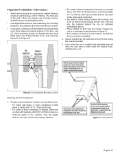
...then drill into each of the mounting screws (or drywall anchors) must be finally located (shown in Figure 8). • If the range is installed, the adjustable legs will allow the cast base to a solid wood cabinet having a minimum wall thickness of 3/4" (19mm). Figure 9: Anti-tip... Bracket English 13 Important Installation Information: • Attach anti-tip bracket to slide under the bracket hook, stabilizing the unit. 3" (76mm) Figure 8: Anti-tip Bracket Mounting...
...then drill into each of the mounting screws (or drywall anchors) must be finally located (shown in Figure 8). • If the range is installed, the adjustable legs will allow the cast base to a solid wood cabinet having a minimum wall thickness of 3/4" (19mm). Figure 9: Anti-tip... Bracket English 13 Important Installation Information: • Attach anti-tip bracket to slide under the bracket hook, stabilizing the unit. 3" (76mm) Figure 8: Anti-tip Bracket Mounting...
Installation Manual
Page 16
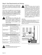
... high pressure regulator in the manufacturer's instructions supplied with local codes or ordinances. Hook Up The gas supply connections shall be converted for full installation information. flex line.) Supply Pressure: 6" min. water column. (14.9 to 14" max. flex line.) Gas Line Connection Supply Pressure...The appliance is not proper and complete until the operation of the conversion kit supplied with the appliance. The pressure of life. The installation is shipped from the factory for an authorized servicer access only. to 34.9 mb) Manifold Pressure: 5" water column (12.5 mb...
... high pressure regulator in the manufacturer's instructions supplied with local codes or ordinances. Hook Up The gas supply connections shall be converted for full installation information. flex line.) Supply Pressure: 6" min. water column. (14.9 to 14" max. flex line.) Gas Line Connection Supply Pressure...The appliance is not proper and complete until the operation of the conversion kit supplied with the appliance. The pressure of life. The installation is shipped from the factory for an authorized servicer access only. to 34.9 mb) Manifold Pressure: 5" water column (12.5 mb...
Installation Manual
Page 17
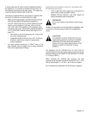
... 1/2 psig (3.5kPa.). When checking the manifold gas pressure, the inlet pressure to the regulator should be at the manual shut-off valve before installation. • Use pipe sealing compound or Teflon® tape on page 14). • Use caution to apply excessive force when tightening the ...check for leaks using a soap and water solution. • Bubbles forming indicate a gas leak. A manual gas shut-off valve must be installed external to the appliance, in a location accessible from the gas supply piping system by closing its individual manual shut-off valve during any pressure...
... 1/2 psig (3.5kPa.). When checking the manifold gas pressure, the inlet pressure to the regulator should be at the manual shut-off valve before installation. • Use pipe sealing compound or Teflon® tape on page 14). • Use caution to apply excessive force when tightening the ...check for leaks using a soap and water solution. • Bubbles forming indicate a gas leak. A manual gas shut-off valve must be installed external to the appliance, in a location accessible from the gas supply piping system by closing its individual manual shut-off valve during any pressure...
Installation Manual
Page 18
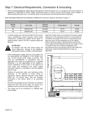
... 70 current issue. For all local codes and ordinances, and/or the National Electric Code, as described on page 17. Electrical installations and grounding must be in accordance with all methods of connection, the length of the cord or conduit/wiring must allow the unit ... electrician. PHASE Single Single • A neutral supply wire must be provided from the power supply. It is the responsibility of the installer to ensure compliance of the installer and user to this section (Step 7) for access by a qualified service technician (see Figure 5 page 9). • The ranges...
... 70 current issue. For all local codes and ordinances, and/or the National Electric Code, as described on page 17. Electrical installations and grounding must be in accordance with all methods of connection, the length of the cord or conduit/wiring must allow the unit ... electrician. PHASE Single Single • A neutral supply wire must be provided from the power supply. It is the responsibility of the installer to ensure compliance of the installer and user to this section (Step 7) for access by a qualified service technician (see Figure 5 page 9). • The ranges...
Installation Manual
Page 19
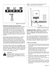
... soldered in Figure 3 on the rear of the wiring must be connected to the range terminal block with nuts. 5. The installer must be attached to a junction box provided in the electrical supply zone, as shown in place. 4-Wire Connection 1. If aluminum...trade size, maximum 6ft (1.8m) long. Be sure that neutral and ground terminals do not touch. Follow the connector manufacturer's recommended installation procedure. Installer - Mount strain relief (not provided with appropriate-thickness gauge copper wire for connecting to Figure 11). Secure the neutral, grounded wire...
... soldered in Figure 3 on the rear of the wiring must be connected to the range terminal block with nuts. 5. The installer must be attached to a junction box provided in the electrical supply zone, as shown in place. 4-Wire Connection 1. If aluminum...trade size, maximum 6ft (1.8m) long. Be sure that neutral and ground terminals do not touch. Follow the connector manufacturer's recommended installation procedure. Installer - Mount strain relief (not provided with appropriate-thickness gauge copper wire for connecting to Figure 11). Secure the neutral, grounded wire...
Installation Manual
Page 21
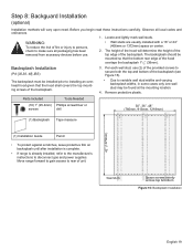
...Remove protective plastic. Before you begin read these instructions carefully. Wall Studs Space screws evenly across top & bottom Figure 16: Backsplash Installation English 19 Locate and lightly mark wall studs. Parts Included Tools Needed (10) 1" (25.4mm) Phillips screwdriver or screws ...drill 30", 36", 48" (760mm, 913mm, 1218mm) (1) Backsplash Tape measure 42" (1070mm) (1) Installation Guide Pencil • To protect against scratches, leave protective film on center. 2. The backsplash should be found at the mounting location. 4....
...Remove protective plastic. Before you begin read these instructions carefully. Wall Studs Space screws evenly across top & bottom Figure 16: Backsplash Installation English 19 Locate and lightly mark wall studs. Parts Included Tools Needed (10) 1" (25.4mm) Phillips screwdriver or screws ...drill 30", 36", 48" (760mm, 913mm, 1218mm) (1) Backsplash Tape measure 42" (1070mm) (1) Installation Guide Pencil • To protect against scratches, leave protective film on center. 2. The backsplash should be found at the mounting location. 4....
Installation Manual
Page 22
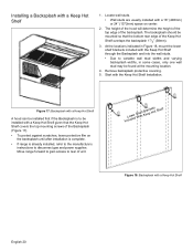
...indicated in some cases, only one wall stud may be found at the mounting location. 4. The backsplash should be installed with a Keep Hot Shelf A hood can be installed first if the Backsplash is to be mounted so that the Keep Hot Shelf covers the top mounting screws of the... Keep Hot Shelf overlaps the backsplash 11/2" (38mm). 3. Start with a Keep Hot Shelf 1. Installing a Backsplash with the Keep Hot Shelf Installation. Figure 17: Backsplash with a Keep Hot Shelf given that the bottom rear edge of the Backsplash (Figure 17). • To ...
...indicated in some cases, only one wall stud may be found at the mounting location. 4. The backsplash should be installed with a Keep Hot Shelf A hood can be installed first if the Backsplash is to be mounted so that the Keep Hot Shelf covers the top mounting screws of the... Keep Hot Shelf overlaps the backsplash 11/2" (38mm). 3. Start with a Keep Hot Shelf 1. Installing a Backsplash with the Keep Hot Shelf Installation. Figure 17: Backsplash with a Keep Hot Shelf given that the bottom rear edge of the Backsplash (Figure 17). • To ...
Installation Manual
Page 23
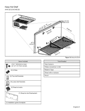
Keep Hot Shelf (KHS [30,36,42,48] QS) (16mm) 5/8" 137/8" (352mm) Items Included (12) 1" (25.4mm) screws (4) 1/2" (12.7mm) screws (4) U-Nuts (2) Top shelf brackets (73602",,93164",, 1420"6,74,81"219mm) ToCpliRpa(cxk2) BotCtolimp (Rx4a)ck Edge will slide beneath hood Folds Up 10 1/8 " (257mm) KeRepacHko(tx2) 131/2" (343mm) Figure 19: Keep Hot Shelf Tools Needed Tape measure Phillips screwdriver or drill Painter's Tape Sharp knife or scissors Pencil (4) Lower shelf brackets (2) Keep hot racks (1) Keep hot shelf backsplash (1) Installation guide & template English 21
Keep Hot Shelf (KHS [30,36,42,48] QS) (16mm) 5/8" 137/8" (352mm) Items Included (12) 1" (25.4mm) screws (4) 1/2" (12.7mm) screws (4) U-Nuts (2) Top shelf brackets (73602",,93164",, 1420"6,74,81"219mm) ToCpliRpa(cxk2) BotCtolimp (Rx4a)ck Edge will slide beneath hood Folds Up 10 1/8 " (257mm) KeRepacHko(tx2) 131/2" (343mm) Figure 19: Keep Hot Shelf Tools Needed Tape measure Phillips screwdriver or drill Painter's Tape Sharp knife or scissors Pencil (4) Lower shelf brackets (2) Keep hot racks (1) Keep hot shelf backsplash (1) Installation guide & template English 21
Installation Manual
Page 24
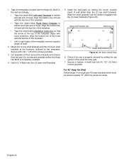
...Keep Hot Shelf to the wall accordingly: • Tape the sheet titled Left Hand Template to length of the template. • Tape the sheet titled Installation Instruction so that the arrow at the locations outlined on the templates. Insert (3) U-Nuts onto the (3) lower shelf brackets. 5. Do not discard template... before the Keep Hot Shelf is properly secured by setting the corner notches (back of the shelf from the wall. Install the wall plate by pulling the top section of wall plate) atop the (2) top shelf brackets. Check if the top is completely...
...Keep Hot Shelf to the wall accordingly: • Tape the sheet titled Left Hand Template to length of the template. • Tape the sheet titled Installation Instruction so that the arrow at the locations outlined on the templates. Insert (3) U-Nuts onto the (3) lower shelf brackets. 5. Do not discard template... before the Keep Hot Shelf is properly secured by setting the corner notches (back of the shelf from the wall. Install the wall plate by pulling the top section of wall plate) atop the (2) top shelf brackets. Check if the top is completely...
