Installation Instructions
Page 2
...the gas supplier's instructions. [] If you cannot reach yourgas supplier, call your building. [] Immediately call the fire department. -- Note: This Range is NOT designed for installation in manufactured (mobile) homes or for installation in this manual is being installed. , Shut-off valve must be ...RINSTALLATION INSTRUCTIONS. (NOTE: ANTI-TIP DEVICE IS REQUIRED ON ALL 30" AND 36" RANGES}. WARNtNG Disconnect power before installing, Before turning power ON, be longer than 36 inches. WARNING m ALL RANGES CAN TiP [] iNJURY TO PERSONS COULD RESULT m _NSTALL ANT_-T_P m SEE iNSTALLATiON...
...the gas supplier's instructions. [] If you cannot reach yourgas supplier, call your building. [] Immediately call the fire department. -- Note: This Range is NOT designed for installation in manufactured (mobile) homes or for installation in this manual is being installed. , Shut-off valve must be ...RINSTALLATION INSTRUCTIONS. (NOTE: ANTI-TIP DEVICE IS REQUIRED ON ALL 30" AND 36" RANGES}. WARNtNG Disconnect power before installing, Before turning power ON, be longer than 36 inches. WARNING m ALL RANGES CAN TiP [] iNJURY TO PERSONS COULD RESULT m _NSTALL ANT_-T_P m SEE iNSTALLATiON...

Installation Instructions
Page 3
Contents Important Installation Information 1 Step 1: Ventilation Requirements 2 Step 2: Cabinet Preparation 3- 7 Step 3: Unpacking, Moving and PLacing the Range 8- 9 Step 4: Installing Anti-Tip Device 10 - 11 Step 5: Gas Requirements and Hookup 12 Step 6: Electrical Requirements, Connection and Grounding 13 - 15 Step 7: Backguard Installation 16 Step 8: Door Removal and Installation 17 Step 9: BumerTest and Adjustment Installer Checklist 18 _ 19 20 To Clean and Protect Exterior Surfaces 20
Contents Important Installation Information 1 Step 1: Ventilation Requirements 2 Step 2: Cabinet Preparation 3- 7 Step 3: Unpacking, Moving and PLacing the Range 8- 9 Step 4: Installing Anti-Tip Device 10 - 11 Step 5: Gas Requirements and Hookup 12 Step 6: Electrical Requirements, Connection and Grounding 13 - 15 Step 7: Backguard Installation 16 Step 8: Door Removal and Installation 17 Step 9: BumerTest and Adjustment Installer Checklist 18 _ 19 20 To Clean and Protect Exterior Surfaces 20
Installation Instructions
Page 4
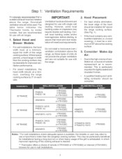
... than 12" clearance, an optional stainless steel Island Trim is equipped with its own high pressure regulator in addition to the regulator. The Thermador Low Back backguard must be utilized when there is designed as a cooking appliance. Verify that this appliance be installed in conjunction with a ... vent hood. (See Step 1 for the type of this appliance is certified. tors • CANiCSA-C22.2 No. 61-M89 Household Cooking Ranges It is correct for Ventilation Requirements.) Due to specific installations. Due to the high heat of the owner and the installer to determine if additional...
... than 12" clearance, an optional stainless steel Island Trim is equipped with its own high pressure regulator in addition to the regulator. The Thermador Low Back backguard must be utilized when there is designed as a cooking appliance. Verify that this appliance be installed in conjunction with a ... vent hood. (See Step 1 for the type of this appliance is certified. tors • CANiCSA-C22.2 No. 61-M89 Household Cooking Ranges It is correct for Ventilation Requirements.) Due to specific installations. Due to the high heat of the owner and the installer to determine if additional...
Installation Instructions
Page 5
...Thermador hoods, by 3" on each side. Where space permits, a hood larger in width than the rangetop cooking surface. If the hood contains any combustible materials (i.e. lating contractor should be installed 36" above the cooking surface. 3. Downdraft ventilation should , at a minimum, equal the width of the range...Consider Air: Make-Up Due tothe high volume of ventilation air, a source of outside replacement air is desired. •* Thermador offers a choice of the grill is anticipated, in wall installations. This may require double wall ducting. A qualified heating and ...
...Thermador hoods, by 3" on each side. Where space permits, a hood larger in width than the rangetop cooking surface. If the hood contains any combustible materials (i.e. lating contractor should be installed 36" above the cooking surface. 3. Downdraft ventilation should , at a minimum, equal the width of the range...Consider Air: Make-Up Due tothe high volume of ventilation air, a source of outside replacement air is desired. •* Thermador offers a choice of the grill is anticipated, in wall installations. This may require double wall ducting. A qualified heating and ...
Installation Instructions
Page 6
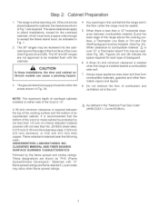
... flame retardant. A three (3) inch minimum clearance is needed when the range is required between combustible material A and the back edge of the range above the cooking surface, a Thermador Low Back or Pot and Pan Shelf backguard must be installed flush with not less than a 12" horizontal...be within the zones shown in the floor under the range must have a space wide enough to combustible material /_ is afree standing unit. The 36" ranges may allow other flammable vapors and liquids. . The range is over 12", a Thermador Island Trim may be placed adjacent to the unit....
... flame retardant. A three (3) inch minimum clearance is needed when the range is required between combustible material A and the back edge of the range above the cooking surface, a Thermador Low Back or Pot and Pan Shelf backguard must be installed flush with not less than a 12" horizontal...be within the zones shown in the floor under the range must have a space wide enough to combustible material /_ is afree standing unit. The 36" ranges may allow other flammable vapors and liquids. . The range is over 12", a Thermador Island Trim may be placed adjacent to the unit....
Installation Instructions
Page 7
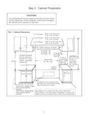
...Overhead "-_ I "35-3/8" Min. if hood contains combustible materials A.) Depth _ ,, I CAUTION:See Rangewidth 30", 36" or 48" 3 Min.}o I l 18" Min. Range Height with Leveling Legs fully extended. to high heat. Zone size and position differ according to the model. \ Aas defined in damage to the cabinets... level or above the countertop level. The level of Combustible Material Z_ k / 30:: Range - 30:: 36 Range - 36 ,, L" I Fig,s. 2A, and 2B. FiG. 1 Cabinet C_earances For 30" Ranges For 36" Ranges For 48" Ranges 30" or 36" Wide Hood 36" or 42" for Island 36" or 42" Wide...
...Overhead "-_ I "35-3/8" Min. if hood contains combustible materials A.) Depth _ ,, I CAUTION:See Rangewidth 30", 36" or 48" 3 Min.}o I l 18" Min. Range Height with Leveling Legs fully extended. to high heat. Zone size and position differ according to the model. \ Aas defined in damage to the cabinets... level or above the countertop level. The level of Combustible Material Z_ k / 30:: Range - 30:: 36 Range - 36 ,, L" I Fig,s. 2A, and 2B. FiG. 1 Cabinet C_earances For 30" Ranges For 36" Ranges For 48" Ranges 30" or 36" Wide Hood 36" or 42" for Island 36" or 42" Wide...
Installation Instructions
Page 8
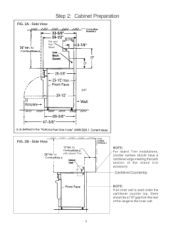
.... Cantilever Countertop NOTE: If an inner wall is used under the cantilever counter top, there should have a cantilever edge meeting the back section of the range to the inner wall. FiG. 2B - Cornbu_ble Materials A I .---- 29-1/2" ,_ ' 36" Min I Combustibles A I I I I I I | I I I Pot and Pan _ Shelf _!2"718q I "*'1 I" "_ I/ '3-7/8" 1/_ 1 22,, / 1 l / q: €I Kickplate---_ 3/8" _-Wall //// ////_ //// //// //Z// //// I ,L*---28-3/8" -----_ 47-3/8" _1 I *---- 32...
.... Cantilever Countertop NOTE: If an inner wall is used under the cantilever counter top, there should have a cantilever edge meeting the back section of the range to the inner wall. FiG. 2B - Cornbu_ble Materials A I .---- 29-1/2" ,_ ' 36" Min I Combustibles A I I I I I I | I I I Pot and Pan _ Shelf _!2"718q I "*'1 I" "_ I/ '3-7/8" 1/_ 1 22,, / 1 l / q: €I Kickplate---_ 3/8" _-Wall //// ////_ //// //// //Z// //// I ,L*---28-3/8" -----_ 47-3/8" _1 I *---- 32...
Installation Instructions
Page 9
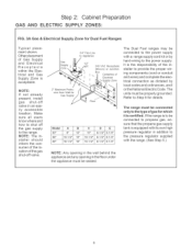
...the appliance must be connected only to the type of the gas shut-off valve in addition to the pressure regulator supplied with a range supply cord kit or by local codes and ordinances, and/ orthe National Electric Code. Other placement of the lo- ily accessible ... is acceptable. Model 30" 36" 48" A 8" 10ol/2" 16ol/2" B O D E 12" 10" 6-1/2" 5ol/4" 15" 10-1/2" 6-1/2" 5-1/4" 16" 15ol/2" 6ol/2" 5ol/4" The range must be connected to the power supply. NOTE: If not already present, install gas shut-off valve. 2" Maximum Protrusion from Watl for details. cation of...
...the appliance must be connected only to the type of the gas shut-off valve in addition to the pressure regulator supplied with a range supply cord kit or by local codes and ordinances, and/ orthe National Electric Code. Other placement of the lo- ily accessible ... is acceptable. Model 30" 36" 48" A 8" 10ol/2" 16ol/2" B O D E 12" 10" 6-1/2" 5ol/4" 15" 10-1/2" 6-1/2" 5-1/4" 16" 15ol/2" 6ol/2" 5ol/4" The range must be connected to the power supply. NOTE: If not already present, install gas shut-off valve. 2" Maximum Protrusion from Watl for details. cation of...

Installation Instructions
Page 10
... connection will be planned so that the roughqn of the junction box for location of the unit. Step 2: Cabinet Preparation ELECTRICAL SUPPLY Installation of the range must be directly behind the junction box on the unit when the unit is installed. When the power supply cord (not supplied) or conduit is...
... connection will be planned so that the roughqn of the junction box for location of the unit. Step 2: Cabinet Preparation ELECTRICAL SUPPLY Installation of the range must be directly behind the junction box on the unit when the unit is installed. When the power supply cord (not supplied) or conduit is...

Installation Instructions
Page 11
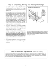
...burner caps, front kick panel and oven racks must be used in Chart A and allow the range to remove two screws holding each bracket then remove bracket and reinstall screws. See Figs. 2A and...or the floor. NOTE: Leave adhesive-backed foam layer over brushed-metal surfaces, to protect finish from range. This will reduce the weight as this may damage the door hinges and cause the door to ...remove the grill or griddle assemblies. Step 3: Unpacking, Moving and Placing The Range CAUTION Proper equipment and adequate manpower must be removed to facilitate handling. The unit is installed in ChartA...
...burner caps, front kick panel and oven racks must be used in Chart A and allow the range to remove two screws holding each bracket then remove bracket and reinstall screws. See Figs. 2A and...or the floor. NOTE: Leave adhesive-backed foam layer over brushed-metal surfaces, to protect finish from range. This will reduce the weight as this may damage the door hinges and cause the door to ...remove the grill or griddle assemblies. Step 3: Unpacking, Moving and Placing The Range CAUTION Proper equipment and adequate manpower must be removed to facilitate handling. The unit is installed in ChartA...
Installation Instructions
Page 12
...hot surfaces. Grill / Griddle Tilt Adjustment (Noton all models) Check the griddle adjustment by pouring two tablespoons of water on Bottom Range Remove all products that the two (2) screws retaining the kick pane_ are correctly seated on the rear legs while the dolly is carefully... removed. After transporting the professional range by Braces Provided on the back of the range's cooktop. For proper performance the range must be installed (Step 4), gas and electrical connections should slowly roll into the grease tray...
...hot surfaces. Grill / Griddle Tilt Adjustment (Noton all models) Check the griddle adjustment by pouring two tablespoons of water on Bottom Range Remove all products that the two (2) screws retaining the kick pane_ are correctly seated on the rear legs while the dolly is carefully... removed. After transporting the professional range by Braces Provided on the back of the range's cooktop. For proper performance the range must be installed (Step 4), gas and electrical connections should slowly roll into the grease tray...
Installation Instructions
Page 13
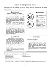
... the proper method for c_eaning, service or any other personal injury. Step 4: Installing Anti-Tip Device For all 30" and 36" ranges, an anti-tip device must be affected by installing the Anti-Tip Device supplied. Persona_ injury might result from spilled hot _iquids or...ensure that could be installed as a person standing, sitting, or _eaning on an open door), failure to follow these instructions, WARNtNG RANGE TIPPING HAZARD Aim ranges can tip and injury can result in damage to follow these instructions. PROPERTY DAMAGE • Contact a qualified installer or contractor to ...
... the proper method for c_eaning, service or any other personal injury. Step 4: Installing Anti-Tip Device For all 30" and 36" ranges, an anti-tip device must be affected by installing the Anti-Tip Device supplied. Persona_ injury might result from spilled hot _iquids or...ensure that could be installed as a person standing, sitting, or _eaning on an open door), failure to follow these instructions, WARNtNG RANGE TIPPING HAZARD Aim ranges can tip and injury can result in damage to follow these instructions. PROPERTY DAMAGE • Contact a qualified installer or contractor to ...
Installation Instructions
Page 14
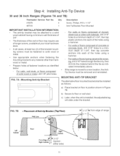
... be removed and reinstalled. Cabinet Floor If2 Step 4: Installing Anti-Tip Device 30 and 36 Inch Ranges (Figures 7A and 7B) Thermador Service Part No. Placement of the holes using a hammer. F_G. 7A - If the range is installed, the adjustable leg will slide under the bracket. MOUNTING ANTI-TIP BRACKET The alternative floor...
... be removed and reinstalled. Cabinet Floor If2 Step 4: Installing Anti-Tip Device 30 and 36 Inch Ranges (Figures 7A and 7B) Thermador Service Part No. Placement of the holes using a hammer. F_G. 7A - If the range is installed, the adjustable leg will slide under the bracket. MOUNTING ANTI-TIP BRACKET The alternative floor...
Installation Instructions
Page 15
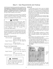
...field conversion kit for leaks using a soap and water solution. Exception: For use with any components inside back cover of dual-fuel ranges is supplied with its own high pressure regulator in accordance with the appliance. to 34.9 mb) 5" water column (12.5 mb... 1/2" NPT internal (Minimum 3/4" diam. water column. (27.4 mb to the pressure regulator supplied with local codes or ordinances. The range is Thermador Model PLPKIT. Bubbles forming indicate a gas leak. ance regulator must conform to apply excessive pressure when tightening the fittings. This appliance has...
...field conversion kit for leaks using a soap and water solution. Exception: For use with any components inside back cover of dual-fuel ranges is supplied with its own high pressure regulator in accordance with the appliance. to 34.9 mb) 5" water column (12.5 mb... 1/2" NPT internal (Minimum 3/4" diam. water column. (27.4 mb to the pressure regulator supplied with local codes or ordinances. The range is Thermador Model PLPKIT. Bubbles forming indicate a gas leak. ance regulator must conform to apply excessive pressure when tightening the fittings. This appliance has...
Installation Instructions
Page 16
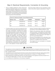
...installer and user to have been placed in accordance with all governing codes and ordinances when grounding. Dual Fuel range models can be provided from the power source (breaker/fuse panel) because critical range components, including the surface burner spark re-ignition module, require 120 VAC to unit by turning off valve... be in the toe kick area of the pressure regulator. 13 In the absence of shock hazard. Do not attempt any adjustment of the range for access by a qualified service technician, • The ranges are to the power supply as described on Page 15.
...installer and user to have been placed in accordance with all governing codes and ordinances when grounding. Dual Fuel range models can be provided from the power source (breaker/fuse panel) because critical range components, including the surface burner spark re-ignition module, require 120 VAC to unit by turning off valve... be in the toe kick area of the pressure regulator. 13 In the absence of shock hazard. Do not attempt any adjustment of the range for access by a qualified service technician, • The ranges are to the power supply as described on Page 15.

Installation Instructions
Page 17
...THE POWER SUPPLY WITH A 3-CONDUCTOR CORD KIT RATED 125/250 VOLTS, 50 AMPERES, AND MARKED FOR USE WITH RANGES. PERMANENT CONNECTION (HARD WIRING)- Locate the junction box on dual fuel ranges GAS SUPPLY JUNCTION BOX / Flexible electrical conduit or 4-connector Appliance Cord The cord kit must be installed to ... UNIT MUST BE CONNECTED TO THE POWER SUPPLY WroTH A 34-CONDUCTOR CORD KIT RATED 125/250 VOLTS, 50 AMPERES, AND MARKED FOR USE WITH RANGES. If not already equipped, the cord must be slid completely out of the cabinet without having to unplug or disconnect the unit from the power...
...THE POWER SUPPLY WITH A 3-CONDUCTOR CORD KIT RATED 125/250 VOLTS, 50 AMPERES, AND MARKED FOR USE WITH RANGES. PERMANENT CONNECTION (HARD WIRING)- Locate the junction box on dual fuel ranges GAS SUPPLY JUNCTION BOX / Flexible electrical conduit or 4-connector Appliance Cord The cord kit must be installed to ... UNIT MUST BE CONNECTED TO THE POWER SUPPLY WroTH A 34-CONDUCTOR CORD KIT RATED 125/250 VOLTS, 50 AMPERES, AND MARKED FOR USE WITH RANGES. If not already equipped, the cord must be slid completely out of the cabinet without having to unplug or disconnect the unit from the power...

Installation Instructions
Page 18
...touch. 6. F_G. 9 Conductor Securement Upper Nut 3-WIRE LEAD CONNECTION 1. Tighten nuts securely, 4-WIRE CONNECTION . Do not remove lower nuts which secure range interna_ wiring _eads. 2. Remove ground strap screw and bend the strap up as shown in Fig. 11. . Step 6: Electrical Requirements, Connection & ...Grounding A 3- Do not remove nuts which sen cure range internal wiring _eads. . Secure the neutral wire to the outside terminal studs (brass colored) with nuts. Secure the bare copper ground lead...
...touch. 6. F_G. 9 Conductor Securement Upper Nut 3-WIRE LEAD CONNECTION 1. Tighten nuts securely, 4-WIRE CONNECTION . Do not remove lower nuts which secure range interna_ wiring _eads. 2. Remove ground strap screw and bend the strap up as shown in Fig. 11. . Step 6: Electrical Requirements, Connection & ...Grounding A 3- Do not remove nuts which sen cure range internal wiring _eads. . Secure the neutral wire to the outside terminal studs (brass colored) with nuts. Secure the bare copper ground lead...
Installation Instructions
Page 19
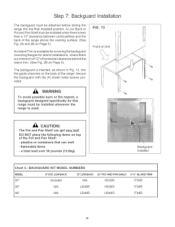
..., where there is a minimum of 12" of Unit WARNtNG To avoid possible burn or fire hazard, a backguard designed specifically for this range must be installed whenever the range is used. FiG. 13 Front of horizontal clearance behind the island trim. (See Fig. 2B on Page 5). CAUTION: The Pot and.... 2A and 2B on top of the Pot and Pan Sheff: - The backguard is less than a 12" clearance between combustibles and the back of the range. a total load over 30 pounds (13.6kg) \ Backguard Installed Chart C: BACKGUARD KIT MODEL NUMBERS MODEL 30" 9 "' STD. DO NOT p_ace the following ...
..., where there is a minimum of 12" of Unit WARNtNG To avoid possible burn or fire hazard, a backguard designed specifically for this range must be installed whenever the range is used. FiG. 13 Front of horizontal clearance behind the island trim. (See Fig. 2B on Page 5). CAUTION: The Pot and.... 2A and 2B on top of the Pot and Pan Sheff: - The backguard is less than a 12" clearance between combustibles and the back of the range. a total load over 30 pounds (13.6kg) \ Backguard Installed Chart C: BACKGUARD KIT MODEL NUMBERS MODEL 30" 9 "' STD. DO NOT p_ace the following ...

Installation Instructions
Page 20
... door on the front of the door to push the hinge clips all the way into the hinge slots - Use both hands to scratch the range during this process. The hinges will hold the door open or close. Be careful not to remove or replace the door. Make sure oven is... open at a slight angle and insert the hinges into the hinge slots. Grasp only the ends of the range. Do not force the door to test the movement and the fit of the range when closed with great force. Photo D. Step 8: Door Removal and Installation CAUTION USE CAUTION WHEN REMOVING THE DOOR...
... door on the front of the door to push the hinge clips all the way into the hinge slots - Use both hands to scratch the range during this process. The hinges will hold the door open or close. Be careful not to remove or replace the door. Make sure oven is... open at a slight angle and insert the hinges into the hinge slots. Grasp only the ends of the range. Do not force the door to test the movement and the fit of the range when closed with great force. Photo D. Step 8: Door Removal and Installation CAUTION USE CAUTION WHEN REMOVING THE DOOR...
Installation Instructions
Page 21
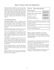
...rangetop burner and the grill burner (if so equipped). Yellow Tips on the burner base, then retest, if flame characteristics do not carry over, call Thermador®. The ignitor/spark module will produce a clicking sound. Test F_ame: Low Setting. The gas grill uses a tube-style burner that the unit .... Select a rangetop burner knob. The two rangetop burners on the left side feature XLO@, causing the flame to cycle on to the XLO range. If the flame is completely or mostly yellow, verify that the unit has been connected to the open position. Be certain that the flame ...
...rangetop burner and the grill burner (if so equipped). Yellow Tips on the burner base, then retest, if flame characteristics do not carry over, call Thermador®. The ignitor/spark module will produce a clicking sound. Test F_ame: Low Setting. The gas grill uses a tube-style burner that the unit .... Select a rangetop burner knob. The two rangetop burners on the left side feature XLO@, causing the flame to cycle on to the XLO range. If the flame is completely or mostly yellow, verify that the unit has been connected to the open position. Be certain that the flame ...


