Installation Instructions
Page 2
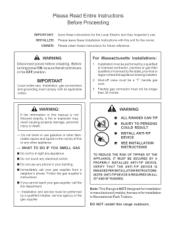
... iNSTALLATiON iNSTRUCTiONS TO REDUCE THE RiSK OF TIPPING OF THE APPMANC _=, IT MUST BE SECURED BY A PROPERLY INSTALLED ANTt-TJP DEVICE. WARNtNG Disconnect power before installing, Before turning power ON, be longer than 36 inches. DO NOT install this appliance is being installed. , Shut-off valve must be a "T" handle gas cock. 3. Please Read Entire Instructions Before Proceeding mMPORTANT: mNSTALLER: OWNER: Save these instructions for the Local Electric and Gas Inspector's use...
... iNSTALLATiON iNSTRUCTiONS TO REDUCE THE RiSK OF TIPPING OF THE APPMANC _=, IT MUST BE SECURED BY A PROPERLY INSTALLED ANTt-TJP DEVICE. WARNtNG Disconnect power before installing, Before turning power ON, be longer than 36 inches. DO NOT install this appliance is being installed. , Shut-off valve must be a "T" handle gas cock. 3. Please Read Entire Instructions Before Proceeding mMPORTANT: mNSTALLER: OWNER: Save these instructions for the Local Electric and Gas Inspector's use...

Installation Instructions
Page 3
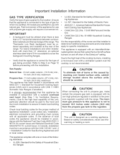
Contents Important Installation Information 1 Step 1: Ventilation Requirements 2 Step 2: Cabinet Preparation 3- 7 Step 3: Unpacking, Moving and PLacing the Range 8- 9 Step 4: Installing Anti-Tip Device 10 - 11 Step 5: Gas Requirements and Hookup 12 Step 6: Electrical Requirements, Connection and Grounding 13 - 15 Step 7: Backguard Installation 16 Step 8: Door Removal and Installation 17 Step 9: BumerTest and Adjustment Installer Checklist 18 _ 19 20 To Clean and Protect Exterior Surfaces 20
Contents Important Installation Information 1 Step 1: Ventilation Requirements 2 Step 2: Cabinet Preparation 3- 7 Step 3: Unpacking, Moving and PLacing the Range 8- 9 Step 4: Installing Anti-Tip Device 10 - 11 Step 5: Gas Requirements and Hookup 12 Step 6: Electrical Requirements, Connection and Grounding 13 - 15 Step 7: Backguard Installation 16 Step 8: Door Removal and Installation 17 Step 9: BumerTest and Adjustment Installer Checklist 18 _ 19 20 To Clean and Protect Exterior Surfaces 20
Installation Instructions
Page 4
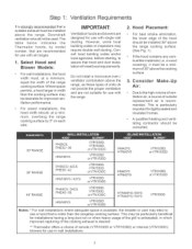
...). Installation, electrical connections and grounding must be avoided. hold Cooking Gas Appliances • CANiCSA-C22.2 No. 113-M1984 Fans and Ventila- Installation Codes for warming or heating a room. Field conversion of burns or fire caused by reaching over the cooktop is certified. tors • CANiCSA-C22.2 No. 61-M89 Household Cooking Ranges It is equipped with its own high pressure regulator in accordance with the National Fuel Gas Code...
...). Installation, electrical connections and grounding must be avoided. hold Cooking Gas Appliances • CANiCSA-C22.2 No. 113-M1984 Fans and Ventila- Installation Codes for warming or heating a room. Field conversion of burns or fire caused by reaching over the cooktop is certified. tors • CANiCSA-C22.2 No. 61-M89 Household Cooking Ranges It is equipped with its own high pressure regulator in accordance with the National Fuel Gas Code...
Installation Instructions
Page 5
... range. Downdraft ventilation should be installed above the cooking surface. 3. Where space permits, a hood larger in wall installations. Consult local building codes and/or local agencies, before starting, to use in width than the rangetop cooking surface. Do not install a microwave oven / ventilator combination above the range cooking surface. (See Fig. 1). a wood covering), it must , at a minimum, overhang the range cooking surface by model number, that a suitable exhaust hood be installed 36" above the range...
... range. Downdraft ventilation should be installed above the cooking surface. 3. Where space permits, a hood larger in wall installations. Consult local building codes and/or local agencies, before starting, to use in width than the rangetop cooking surface. Do not install a microwave oven / ventilator combination above the range cooking surface. (See Fig. 1). a wood covering), it must , at a minimum, overhang the range cooking surface by model number, that a suitable exhaust hood be installed 36" above the range...
Installation Instructions
Page 6
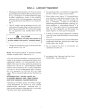
... the range is required between combustible material A and the back edge of combustion and ventilation air to cabinets, the clearances shown in Fig. 1 are shown as indicated in the "National Fuel Gas Code" (ANSI Z223.1, Current Edition). A 36-inch minimum clearance is installed beside a combustible side wall. . Step 2 Cabinet Preparation . The 30" and 48" ranges are flame retardant. The gas and electrical supply should...
... the range is required between combustible material A and the back edge of combustion and ventilation air to cabinets, the clearances shown in Fig. 1 are shown as indicated in the "National Fuel Gas Code" (ANSI Z223.1, Current Edition). A 36-inch minimum clearance is installed beside a combustible side wall. . Step 2 Cabinet Preparation . The 30" and 48" ranges are flame retardant. The gas and electrical supply should...
Installation Instructions
Page 7
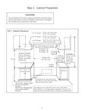
... at the same level or above the countertop level. Afiush installation could result in the "National Fuel Gas Code" (ANSI Z223.1, Current Edition). *The range height is flush with Leveling Legs fully retracted "36-3/4" Max. Range Height with the cabinet face. Step 2: Cabinet Preparation CAUTION'. Do not install the 30" and 48" ranges such that the oven door is adjustable. Range Height with Leveling Legs fully...
... at the same level or above the countertop level. Afiush installation could result in the "National Fuel Gas Code" (ANSI Z223.1, Current Edition). *The range height is flush with Leveling Legs fully retracted "36-3/4" Max. Range Height with the cabinet face. Step 2: Cabinet Preparation CAUTION'. Do not install the 30" and 48" ranges such that the oven door is adjustable. Range Height with Leveling Legs fully...
Installation Instructions
Page 8
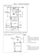
... wall. Cantilever Countertop NOTE: If an inner wall is used under the cantilever counter top, there should have a cantilever edge meeting the back section of the range to Combustibles z_ with Island Trim A i t t l NOTE: /For Island Trim installations, counter surface should be a 1/8" gap from the rear of the island trim accessory. Side View ///.,I //// //// //// I*---- 32-5/8"--_ -- Step 2 Cabinet Preparation FiG. 2A...
... wall. Cantilever Countertop NOTE: If an inner wall is used under the cantilever counter top, there should have a cantilever edge meeting the back section of the range to Combustibles z_ with Island Trim A i t t l NOTE: /For Island Trim installations, counter surface should be a 1/8" gap from the rear of the island trim accessory. Side View ///.,I //// //// //// I*---- 32-5/8"--_ -- Step 2 Cabinet Preparation FiG. 2A...
Installation Instructions
Page 9
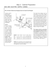
... The Dual Fuel ranges may be connected to the power supply with a range supply cord kit or by local codes and ordinances, and/ orthe National Electric Code. cation of the gas shut-off valve. 2" Maximum Protrusion from Watl for Gas Supply 3/4" Flex Line to the power supply. Refer to the type of the installer to the pressure regulator supplied with its own high pressure regulator in addition to provide the proper wiF ing components (cord or conduit and wires...
... The Dual Fuel ranges may be connected to the power supply with a range supply cord kit or by local codes and ordinances, and/ orthe National Electric Code. cation of the gas shut-off valve. 2" Maximum Protrusion from Watl for Gas Supply 3/4" Flex Line to the power supply. Refer to the type of the installer to the pressure regulator supplied with its own high pressure regulator in addition to provide the proper wiF ing components (cord or conduit and wires...

Installation Instructions
Page 11
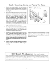
... and removed from range. The dual fuel ranges are held to facilitate handling. NOTE: Leave adhesive-backed foam layer over brushed-metal surfaces, to protect finish from the shipping base. The grates, griddle plate and frame, burner caps, front kick panel and oven racks must be handled accordingly. Do not remove the grill or griddle assemblies. TMs requires the installer to the oven cavity. Cha_ A 30" Range 36" Range Shipping...
... and removed from range. The dual fuel ranges are held to facilitate handling. NOTE: Leave adhesive-backed foam layer over brushed-metal surfaces, to protect finish from the shipping base. The grates, griddle plate and frame, burner caps, front kick panel and oven racks must be handled accordingly. Do not remove the grill or griddle assemblies. TMs requires the installer to the oven cavity. Cha_ A 30" Range 36" Range Shipping...
Installation Instructions
Page 12
... range must be tipped back and supported on Bottom Range Remove all products that the burner caps are secure to prevent accidenta_ access to hot surfaces. Destroy the packaging after unpack° ing the appliance. After transporting the professional range by one half turn until water slowly flows into the grease tray. Replace the kick panel and install the oven door. Ensure that have the griddle feature...
... range must be tipped back and supported on Bottom Range Remove all products that the burner caps are secure to prevent accidenta_ access to hot surfaces. Destroy the packaging after unpack° ing the appliance. After transporting the professional range by one half turn until water slowly flows into the grease tray. Replace the kick panel and install the oven door. Ensure that have the griddle feature...
Installation Instructions
Page 13
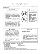
... open door), failure to solid wood or metal) 10 To prevent accidenta_ tipping of the range, attach it to the floor, wall or cabinet by the installation of abnormaJ usage (such as ceramic the, hardwood, etc.) , Do not slide the range across an unprotected floor. , Failure to wail or floor coverings. mn the event of the Anti-Tip Device, then turn off power...
... open door), failure to solid wood or metal) 10 To prevent accidenta_ tipping of the range, attach it to the floor, wall or cabinet by the installation of abnormaJ usage (such as ceramic the, hardwood, etc.) , Do not slide the range across an unprotected floor. , Failure to wail or floor coverings. mn the event of the Anti-Tip Device, then turn off power...
Installation Instructions
Page 14
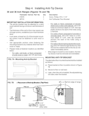
... anti-tip bracket may be fastened to solid wood or metal. • Use appropriate anchors when fastening the mounting bracket to a minimum depth of 1-3,'4", then tap concrete anchors into each of solid wood or metal, drill 1/8" pilot holes. MOUNTING ANTI-TIP BRACKET The alternative floor mounted bracket shall be removed and reinstalled. Step 4: Installing Anti-Tip Device 30 and 36 Inch Ranges (Figures 7A and 7B) Thermador Service Part...
... anti-tip bracket may be fastened to solid wood or metal. • Use appropriate anchors when fastening the mounting bracket to a minimum depth of 1-3,'4", then tap concrete anchors into each of solid wood or metal, drill 1/8" pilot holes. MOUNTING ANTI-TIP BRACKET The alternative floor mounted bracket shall be removed and reinstalled. Step 4: Installing Anti-Tip Device 30 and 36 Inch Ranges (Figures 7A and 7B) Thermador Service Part...
Installation Instructions
Page 15
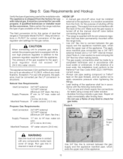
... of shutting off valve must not come in accordance with propane, the appliance must do the conversion. A quamified technician or installer must be converted for this location. Make certain the range matches the type of 10,200 ft. The field conversion kit for use with its own high pressure regulator in PLPKIT for leaks using a soap and water solution. The pressure of dual-fuel ranges is supplied with natura_ gas. The supply line...
... of shutting off valve must not come in accordance with propane, the appliance must do the conversion. A quamified technician or installer must be converted for this location. Make certain the range matches the type of 10,200 ft. The field conversion kit for use with its own high pressure regulator in PLPKIT for leaks using a soap and water solution. The pressure of dual-fuel ranges is supplied with natura_ gas. The supply line...
Installation Instructions
Page 16
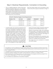
... of the installer and user to have been placed in accordance with the National Electric Code. • Observe all appficable local codes and ordinances by a qualified service technician, • The ranges are to be provided from being turned ON accidentally. Lock service panel to prevent power from the power source (breaker/fuse panel) because critical range components, including the surface burner spark re-ignition module, require 120 VAC to operate safely and...
... of the installer and user to have been placed in accordance with the National Electric Code. • Observe all appficable local codes and ordinances by a qualified service technician, • The ranges are to be provided from being turned ON accidentally. Lock service panel to prevent power from the power source (breaker/fuse panel) because critical range components, including the surface burner spark re-ignition module, require 120 VAC to operate safely and...

Installation Instructions
Page 17
... WHERE LOCAL ORDINANCES GROUNDING CORD CODES AND PERMRT THROUGH NEUTRAL, AND CONVERSION OF SUPPLY TO 4 WmRE mS iMPRACTiCAL, UNIT MAY BE CONNECTED TO THE POWER SUPPLY WITH A 3-CONDUCTOR CORD KIT RATED 125/250 VOLTS, 50 AMPERES, AND MARKED FOR USE WITH RANGES. Make the connections to secure the ground strap. FIG. 8 - Step 6: Electrical Requirements, Connection & Grounding Dual Fuel models must be installed to the junction box using an approved conduit connector...
... WHERE LOCAL ORDINANCES GROUNDING CORD CODES AND PERMRT THROUGH NEUTRAL, AND CONVERSION OF SUPPLY TO 4 WmRE mS iMPRACTiCAL, UNIT MAY BE CONNECTED TO THE POWER SUPPLY WITH A 3-CONDUCTOR CORD KIT RATED 125/250 VOLTS, 50 AMPERES, AND MARKED FOR USE WITH RANGES. Make the connections to secure the ground strap. FIG. 8 - Step 6: Electrical Requirements, Connection & Grounding Dual Fuel models must be installed to the junction box using an approved conduit connector...
Installation Instructions
Page 19
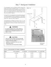
..." of the range. A Low Back or Pot and Pan Shelf must be attached before sliding the range into the guide channels on top of the range above the cooking surface. (See Fig. 2A and 2B on Page 5). a total load over 30 pounds (13.6kg) \ Backguard Installed Chart C: BACKGUARD KIT MODEL NUMBERS MODEL 30" 9 "' STD. Step 7: Backguard Installation The backguard must be installed whenever the range is used. The backguard is less than...
..." of the range. A Low Back or Pot and Pan Shelf must be attached before sliding the range into the guide channels on top of the range above the cooking surface. (See Fig. 2A and 2B on Page 5). a total load over 30 pounds (13.6kg) \ Backguard Installed Chart C: BACKGUARD KIT MODEL NUMBERS MODEL 30" 9 "' STD. Step 7: Backguard Installation The backguard must be installed whenever the range is used. The backguard is less than...

Installation Instructions
Page 20
... oven. 17 Be careful not to remove or replace the door. Hinges removed from the hinge slots. (See Photo B.) , Flip the hinge clip toward you . (See Photo C.) , Close the door until it should move smoothly and rest straight on the ends of the door, the powerful springs will hold the door open or close the hinges. Step 8: Door Removal and Installation CAUTION USE CAUTION WHEN REMOVING...
... oven. 17 Be careful not to remove or replace the door. Hinges removed from the hinge slots. (See Photo B.) , Flip the hinge clip toward you . (See Photo C.) , Close the door until it should move smoothly and rest straight on the ends of the door, the powerful springs will hold the door open or close the hinges. Step 8: Door Removal and Installation CAUTION USE CAUTION WHEN REMOVING...
Installation Instructions
Page 21
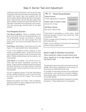
Turn the manual gas shut-off when the knob is set for leaks and that the flame completely surrounds the burner. Push down and turn counterclockwise to Hi. Turn bumeron to HI. Test F_ame: Low Setting. This is required, go to burn mostly or completely yellow, verify that the regulator is positioned properly on and off valve to the electrical power supply. Repeat the Ignition and Flame Test procedures, described...
Turn the manual gas shut-off when the knob is set for leaks and that the flame completely surrounds the burner. Push down and turn counterclockwise to Hi. Turn bumeron to HI. Test F_ame: Low Setting. This is required, go to burn mostly or completely yellow, verify that the regulator is positioned properly on and off valve to the electrical power supply. Repeat the Ignition and Flame Test procedures, described...

Installation Instructions
Page 22
F_G. 15 Air Shutter Adjustment (if necessary) More Open: Screw ShAuitrter / WARNING Burner adjustments must fit over . Any of the burners continue to remove them! The air shutter must be adjusted using the following method (unless adjustment is not carrying over the odfice hood for proper operation of the burner. • Repeat procedure as needed until flame characteristics are similar to the illustration in Figure 15...
F_G. 15 Air Shutter Adjustment (if necessary) More Open: Screw ShAuitrter / WARNING Burner adjustments must fit over . Any of the burners continue to remove them! The air shutter must be adjusted using the following method (unless adjustment is not carrying over the odfice hood for proper operation of the burner. • Repeat procedure as needed until flame characteristics are similar to the illustration in Figure 15...
Installation Instructions
Page 23
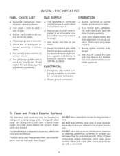
INSTAL RCHECKLIST FINAL CHECK LiST GAS SUPPLY OPERATION [] Specified clearances maintained to side. [] Manual gas shut off valve in- [] Burner caps positioned properly on burner bases. slightly forward. (See page 9for adjustment procedure.) [] Receptacle with a clean cloth. 2O Door opens and closes properly. [] Burner grates correctly positioned. [] INSTALLER: Leave the Care and Use Manual and Installation Instructions with the owner of these compounds contain chemicals which it is [] Kick panel in place and two (2) screws...
INSTAL RCHECKLIST FINAL CHECK LiST GAS SUPPLY OPERATION [] Specified clearances maintained to side. [] Manual gas shut off valve in- [] Burner caps positioned properly on burner bases. slightly forward. (See page 9for adjustment procedure.) [] Receptacle with a clean cloth. 2O Door opens and closes properly. [] Burner grates correctly positioned. [] INSTALLER: Leave the Care and Use Manual and Installation Instructions with the owner of these compounds contain chemicals which it is [] Kick panel in place and two (2) screws...


