Data Sheet
Page 1
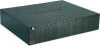
... and Power Supplies status TFC-1600 rev:08.11.2010 Limited Warranty BENEFITS • 1 x 10/100Mbps Fast Ethernet RJ45 port and 1 x RS-232 Console ports for management • Web Browser Based Management via Ethernet port or Command Line Interface Management via RS-232 port • SNMP Agent • Provides media Link/Connection Speed/Duplex status for each bay is electrically isolated from others • 3 Years- fiber 16-Slot Chassis System for TFC series Fiber Converter TFC-1600 TRENDnet's TFC-1600...
... and Power Supplies status TFC-1600 rev:08.11.2010 Limited Warranty BENEFITS • 1 x 10/100Mbps Fast Ethernet RJ45 port and 1 x RS-232 Console ports for management • Web Browser Based Management via Ethernet port or Command Line Interface Management via RS-232 port • SNMP Agent • Provides media Link/Connection Speed/Duplex status for each bay is electrically isolated from others • 3 Years- fiber 16-Slot Chassis System for TFC series Fiber Converter TFC-1600 TRENDnet's TFC-1600...
Data Sheet
Page 2
... • FCC, CE, VCCI RELATED PRODUCTS TFC-1600 TFC-1600RP TFC-1600MM TFC-1600R48 16-Slot Chassis System for TFC series Fiber Converter Redundant Power Supply for the TFC-1600 Management Module for the TFC-1600 48V Redundant Power Supply for TFC-1600 ORDERING INFORMATION 20675 Manhattan Place,Torrance, CA 90501 USA Tel: 1-310-961-5500 Fax: 1-310-961-5511 Web: www.trendnet.com Email: sales@trendnet.com To Order Please Call: 1-888...
... • FCC, CE, VCCI RELATED PRODUCTS TFC-1600 TFC-1600RP TFC-1600MM TFC-1600R48 16-Slot Chassis System for TFC series Fiber Converter Redundant Power Supply for the TFC-1600 Management Module for the TFC-1600 48V Redundant Power Supply for TFC-1600 ORDERING INFORMATION 20675 Manhattan Place,Torrance, CA 90501 USA Tel: 1-310-961-5500 Fax: 1-310-961-5511 Web: www.trendnet.com Email: sales@trendnet.com To Order Please Call: 1-888...

Manual
Page 3
... this user's guide, may cause harmful interference to radio communications. Operation of this product may be required to take adequate measures. This equipment generates, uses, and can radiate radio frequency energy and, if not installed and used in which case the user may cause...the regulations for a Class A digital device, pursuant to provide reasonable protection against harmful interference when the equipment is a Class A product. In a domestic environment, this equipment in a commercial environment. These limits are designed to Part 15 of VCCI Class A Compliance. CE...
... this user's guide, may cause harmful interference to radio communications. Operation of this product may be required to take adequate measures. This equipment generates, uses, and can radiate radio frequency energy and, if not installed and used in which case the user may cause...the regulations for a Class A digital device, pursuant to provide reasonable protection against harmful interference when the equipment is a Class A product. In a domestic environment, this equipment in a commercial environment. These limits are designed to Part 15 of VCCI Class A Compliance. CE...
Manual
Page 5
Installing and Removing the Power Supply 11 UNDERSTANDING LED INDICATORS......... 12 FRONT PANEL 12 POWER AND FAN LED 12 TECHNICAL SPECIFICATIONS 13 ORDERING INFORMATION 15 1. 100TX ~ 100FX MEDIA CONVERTER 15 2. 10/100TX ~ 100FX MEDIA CONVERTER 16 i Connecting to 19-inch standard rack 8 . TABLE OF CONTENTS PREFACE 3 19" MEDIA CONVERTER CHASSIS SYSTEM 4 PRODUCT FEATURES 5 PRODUCT FEATURES 5 UNPACKING AND INSTALLATION 6 UNPACKING 6 INSTALLATION 6 DECIDING HOW TO INSTALL THE SYSTEM 7 . Mounted to Power (Power Supply 10 . Installing Media Converter 9 .
Installing and Removing the Power Supply 11 UNDERSTANDING LED INDICATORS......... 12 FRONT PANEL 12 POWER AND FAN LED 12 TECHNICAL SPECIFICATIONS 13 ORDERING INFORMATION 15 1. 100TX ~ 100FX MEDIA CONVERTER 15 2. 10/100TX ~ 100FX MEDIA CONVERTER 16 i Connecting to 19-inch standard rack 8 . TABLE OF CONTENTS PREFACE 3 19" MEDIA CONVERTER CHASSIS SYSTEM 4 PRODUCT FEATURES 5 PRODUCT FEATURES 5 UNPACKING AND INSTALLATION 6 UNPACKING 6 INSTALLATION 6 DECIDING HOW TO INSTALL THE SYSTEM 7 . Mounted to Power (Power Supply 10 . Installing Media Converter 9 .

Manual
Page 7
... with redundant power supplies. You can order the proprietary media converters and a second power supply separately. 3 Illustrative LEDs functions ?? Introduction of housing up to install and use the 19" Media Converter Chassis System. Installation instructions ?? single-mode) ? 1000BASE-SX/LX ? 1000BASE-LX (multi-mode ? Product features ?? Specifications ?? Below is fitted with only one channel media conversion solution. Ordering Information Attention! PREFACE This manual describes how...
... with redundant power supplies. You can order the proprietary media converters and a second power supply separately. 3 Illustrative LEDs functions ?? Introduction of housing up to install and use the 19" Media Converter Chassis System. Installation instructions ?? single-mode) ? 1000BASE-SX/LX ? 1000BASE-LX (multi-mode ? Product features ?? Specifications ?? Below is fitted with only one channel media conversion solution. Ordering Information Attention! PREFACE This manual describes how...
Manual
Page 8
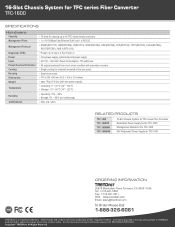
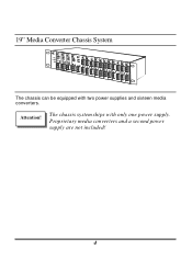
Attention! Proprietary media converters and a second power supply are not included! 4 The chassis system ships with two power supplies and sixteen media converters. 19" Media Converter Chassis System The chassis can be equipped with only one power supply.
Attention! Proprietary media converters and a second power supply are not included! 4 The chassis system ships with two power supplies and sixteen media converters. 19" Media Converter Chassis System The chassis can be equipped with only one power supply.
Manual
Page 9
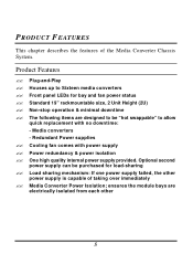
... internal power supply provided. Houses up to allow quick replacement with power supply ?? Cooling fan comes with no downtime: - The following items are electrically isolated from each other power supply is capable of the Media Converter Chassis System. Optional second power supply can be "hot swappable" to Sixteen media converters ?? Load sharing mechanism: If one power supply failed, the other 5 Product Features ?? Front panel LEDs for...
... internal power supply provided. Houses up to allow quick replacement with power supply ?? Cooling fan comes with no downtime: - The following items are electrically isolated from each other power supply is capable of the Media Converter Chassis System. Optional second power supply can be "hot swappable" to Sixteen media converters ?? Load sharing mechanism: If one power supply failed, the other 5 Product Features ?? Front panel LEDs for...

Manual
Page 10
.... User's Manual ?? One power supply installed in the chassis ?? Accessories: rack -mount screws (8 pcs.), rack -mount ears (2 pcs.), rubber foot (4 pcs.) If any damage to the Chassis, we recommend that you read this chapter carefully before starting installation. When installing, take the following into your local reseller for the Chassis. UNPACKING AND INSTALLATION This chapter provides unpacking and installation information for replacement. To...
.... User's Manual ?? One power supply installed in the chassis ?? Accessories: rack -mount screws (8 pcs.), rack -mount ears (2 pcs.), rubber foot (4 pcs.) If any damage to the Chassis, we recommend that you read this chapter carefully before starting installation. When installing, take the following into your local reseller for the Chassis. UNPACKING AND INSTALLATION This chapter provides unpacking and installation information for replacement. To...
Manual
Page 11
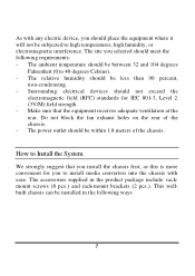
.... - Do not block the fan exhaust holes on the rear of the chassis. How to high temperatures, high humidity, or electromagnetic interference. The power outlet should place the equipment where it will not be subjected to Install the System We strongly...device, you selected should be installed in the product package include: rackmount screws (8 pcs.) and rack-mount brackets (2 pcs.). The relative humidity should meet the following ways: 7 Make sure that you install the chassis first, as this is more convenient for IEC 801-3, Level 2 (3V/M) field strength. - The accessories supplied...
.... - Do not block the fan exhaust holes on the rear of the chassis. How to high temperatures, high humidity, or electromagnetic interference. The power outlet should place the equipment where it will not be subjected to Install the System We strongly...device, you selected should be installed in the product package include: rackmount screws (8 pcs.) and rack-mount brackets (2 pcs.). The relative humidity should meet the following ways: 7 Make sure that you install the chassis first, as this is more convenient for IEC 801-3, Level 2 (3V/M) field strength. - The accessories supplied...

Manual
Page 12
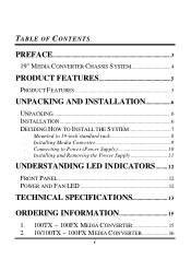
Step 2: Carefully position the chassis into any EIA 19" standard rack. Align the brackets to the screw holes on the rack and use rack screws to both sides of the chassis. Step 1: Attach the brackets to secure the chassis on the rack. Step 3: Proceed to the "Connecting to each side and secure them. Apply four screws to Power" section. 8 .Mounting to 19-inch standard rack Use the rack-mount brackets and screws to install the chassis into the rack.
Step 2: Carefully position the chassis into any EIA 19" standard rack. Align the brackets to the screw holes on the rack and use rack screws to both sides of the chassis. Step 1: Attach the brackets to secure the chassis on the rack. Step 3: Proceed to the "Connecting to each side and secure them. Apply four screws to Power" section. 8 .Mounting to 19-inch standard rack Use the rack-mount brackets and screws to install the chassis into the rack.
Manual
Page 13
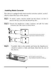
...out of the carrier as shown below. Unscrew the hand screw counter clockwise by using hand or screwdriver and pull the media converter module out on the carrier Step 3: Carefully slide in the module and fasten the thumbscrew clockwise until it is fitted into the slot of the ...and fasten the hand screw clockwise by using hand or screwdriver. 9 .Installing Media Converter The chassis is equipped with sixteen media converter carriers, each of which is fully and firmly fitted into bays of the chassis. Step 1: To install a media converter module onto the chassis, you have to unscrew...
...out of the carrier as shown below. Unscrew the hand screw counter clockwise by using hand or screwdriver and pull the media converter module out on the carrier Step 3: Carefully slide in the module and fasten the thumbscrew clockwise until it is fitted into the slot of the ...and fasten the hand screw clockwise by using hand or screwdriver. 9 .Installing Media Converter The chassis is equipped with sixteen media converter carriers, each of which is fully and firmly fitted into bays of the chassis. Step 1: To install a media converter module onto the chassis, you have to unscrew...

Manual
Page 14
... is free from the Chassis, the chassis will instantaneously take 100% of each converter bay comes from the others under a certain protection mechanism, so that might occur to the power supplies or faulty converter bay. Each bay is isolated from the two shared power supplies. .Connecting to Power (Power Supply) The chassis ships with two power supplies, you may remove any connection loss...
... is free from the Chassis, the chassis will instantaneously take 100% of each converter bay comes from the others under a certain protection mechanism, so that might occur to the power supplies or faulty converter bay. Each bay is isolated from the two shared power supplies. .Connecting to Power (Power Supply) The chassis ships with two power supplies, you may remove any connection loss...
Manual
Page 15
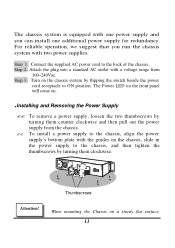
... power supplies. To install a power supply to the chassis, and then tighten the thumbscrews by turning them clockwise. When mounting the Chassis on the chassis, slide in the power supply to the chassis, align the power supply's bottom plate with the guides on a sturdy flat surface, 11 Step 3: Turn on . .Installing and Removing the Power Supply ?? The Power LED on the front panel will come on the chassis system by using...
... power supplies. To install a power supply to the chassis, and then tighten the thumbscrews by turning them clockwise. When mounting the Chassis on the chassis, slide in the power supply to the chassis, align the power supply's bottom plate with the guides on a sturdy flat surface, 11 Step 3: Turn on . .Installing and Removing the Power Supply ?? The Power LED on the front panel will come on the chassis system by using...
Manual
Page 16
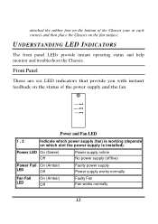
... installed). attached the rubber foot on the bottom of the power supply and the fan. 12 POWERON POWER FAIL FAN FAIL Power and Fan LED 1 , 2 Indicate which slot the power supply is working (depends on the flat surface. UNDERSTANDING LED INDICATORS The front panel LEDs provide instant operating status and help monitor and troubleshoot the Chassis. Power LED On (Green) Off Power supply online No power supply (offline) Power Fail On (Amber) LED Off Faulty power supply Power supply works...
... installed). attached the rubber foot on the bottom of the power supply and the fan. 12 POWERON POWER FAIL FAN FAIL Power and Fan LED 1 , 2 Indicate which slot the power supply is working (depends on the flat surface. UNDERSTANDING LED INDICATORS The front panel LEDs provide instant operating status and help monitor and troubleshoot the Chassis. Power LED On (Green) Off Power supply online No power supply (offline) Power Fail On (Amber) LED Off Faulty power supply Power supply works...
Manual
Page 17
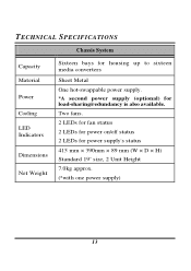
TECHNICAL SPECIFICATIONS Capacity Material Power Cooling LED Indicators Dimensions Net Weight Chassis System Sixteen bays for housing up to sixteen media converters Sheet Metal One hot-swappable power supply. *A second power supply (optional) for power supply's status 415 mm × 390mm × 89 mm (W × D × H) Standard 19" size, 2 Unit Height 7.0kg approx. (*with one power supply) 13 Two fans. 2 LEDs for fan status 2 LEDs for power on/off status 2 LEDs for load-sharing/redundancy is also available.
TECHNICAL SPECIFICATIONS Capacity Material Power Cooling LED Indicators Dimensions Net Weight Chassis System Sixteen bays for housing up to sixteen media converters Sheet Metal One hot-swappable power supply. *A second power supply (optional) for power supply's status 415 mm × 390mm × 89 mm (W × D × H) Standard 19" size, 2 Unit Height 7.0kg approx. (*with one power supply) 13 Two fans. 2 LEDs for fan status 2 LEDs for power on/off status 2 LEDs for load-sharing/redundancy is also available.
Manual
Page 18
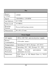
C, Storage: -10?~50? C Operating: 10% ~ 90%, Storage: 5% ~ 90% "Short Circuit" automatic recovery prevention with FCC Class A, CE Mark Class A, VCCI Class A 14 Rated Voltage Speed Air Delivery Noise Level Bearing System Dimensions Fan 12VDC 3200 RPM +/- 250 RPM 42.5 CFM 36.5dB(A) Precise ball bearing system 80 × 80 × 25 mm AC inputs: Power Consumption: Temperature Humidity Overload Protection Emissions: Power Supply 100 to 240 VAC, universal power supply 150 watts. (max.) Operating: 0?~40?
C, Storage: -10?~50? C Operating: 10% ~ 90%, Storage: 5% ~ 90% "Short Circuit" automatic recovery prevention with FCC Class A, CE Mark Class A, VCCI Class A 14 Rated Voltage Speed Air Delivery Noise Level Bearing System Dimensions Fan 12VDC 3200 RPM +/- 250 RPM 42.5 CFM 36.5dB(A) Precise ball bearing system 80 × 80 × 25 mm AC inputs: Power Consumption: Temperature Humidity Overload Protection Emissions: Power Supply 100 to 240 VAC, universal power supply 150 watts. (max.) Operating: 0?~40?

Manual
Page 19
... 15km 30km 40km 60km 15 SMF (singlemode fiber). ORDERING INFORMATION Note: Please contact your dealer for product model name and availability. 1. 100Base-TX ~ 100Base-FX Media Converters # Port One Port Two Speed 1-1 100TX 1-2 100TX 1-3 100TX 1-4 100TX 1-5 100TX 1-6 100TX 1-7 100TX 1-8 100TX Cable / Connector 2-pairs Cat. 5 RJ-45 2-pairs Cat. 5 RJ-45 2-pairs Cat. 5 RJ-45 2-pairs Cat...
... 15km 30km 40km 60km 15 SMF (singlemode fiber). ORDERING INFORMATION Note: Please contact your dealer for product model name and availability. 1. 100Base-TX ~ 100Base-FX Media Converters # Port One Port Two Speed 1-1 100TX 1-2 100TX 1-3 100TX 1-4 100TX 1-5 100TX 1-6 100TX 1-7 100TX 1-8 100TX Cable / Connector 2-pairs Cat. 5 RJ-45 2-pairs Cat. 5 RJ-45 2-pairs Cat. 5 RJ-45 2-pairs Cat...

Manual
Page 20
2. 10/100Base-TX ~ 100Base-FX Media Converters # Speed 2-1 10/100 TX 2-2 10/100 TX 2-3 10/100 TX 2-4 10/100 TX 2-5 10/100 TX 2-6 10/100 TX 2-7 10/100 TX 2-8 10/100 TX Port One Cable / Connector 2-pairs Cat. 5 RJ-45 2-pairs Cat. 5 RJ-45 2-pairs Cat. 5 RJ-45 2-pairs Cat. 5 RJ-45 2-pairs Cat... Cat. 5 RJ-45 2-pairs Cat. 5 RJ-45 2-pairs Cat. 5 RJ-45 Distance 100m 100m 100m 100m 100m 100m 100m 100m Speed 100FX 100FX 100FX 100FX 100FX 100FX 100FX 100FX Port Two Cable (/125µm) Connector MMF (50µm or 62.5µm) SC MMF (50µm or 62.5µm) ST MMF (50µm or...
2. 10/100Base-TX ~ 100Base-FX Media Converters # Speed 2-1 10/100 TX 2-2 10/100 TX 2-3 10/100 TX 2-4 10/100 TX 2-5 10/100 TX 2-6 10/100 TX 2-7 10/100 TX 2-8 10/100 TX Port One Cable / Connector 2-pairs Cat. 5 RJ-45 2-pairs Cat. 5 RJ-45 2-pairs Cat. 5 RJ-45 2-pairs Cat. 5 RJ-45 2-pairs Cat... Cat. 5 RJ-45 2-pairs Cat. 5 RJ-45 2-pairs Cat. 5 RJ-45 Distance 100m 100m 100m 100m 100m 100m 100m 100m Speed 100FX 100FX 100FX 100FX 100FX 100FX 100FX 100FX Port Two Cable (/125µm) Connector MMF (50µm or 62.5µm) SC MMF (50µm or 62.5µm) ST MMF (50µm or...

Manual
Page 21
...Cat. 5 RJ-45 4-pairs Cat. 5 RJ-45 4-pairs Cat. 5 RJ-45 Distance 100m 100m 100m 3-4 1000T 4-pairs Cat. 5 RJ-45 100m Speed 1000SX 1000SX 1000LX 1000LX Port Two Cable (/125µm) Connector MMF of 850nm (50µ m) SC MMF of 850nm (62.5µ m) SC SMF (9µm or 10µm) SC SMF ...(9µm or 10µm) SC Distance 550m 220m 10km 20km 4. 100Base-FX ~ 100Base-FX Media Converters # Speed 4-1 100FX 4-2 100FX 4-3 100FX 4-4 100FX Port One Cable / Connector MMF (50µm or 62.5µ m) SC MMF (50µm or 62.5µ m) SC MMF (50µm or 62.5µ...
...Cat. 5 RJ-45 4-pairs Cat. 5 RJ-45 4-pairs Cat. 5 RJ-45 Distance 100m 100m 100m 3-4 1000T 4-pairs Cat. 5 RJ-45 100m Speed 1000SX 1000SX 1000LX 1000LX Port Two Cable (/125µm) Connector MMF of 850nm (50µ m) SC MMF of 850nm (62.5µ m) SC SMF (9µm or 10µm) SC SMF ...(9µm or 10µm) SC Distance 550m 220m 10km 20km 4. 100Base-FX ~ 100Base-FX Media Converters # Speed 4-1 100FX 4-2 100FX 4-3 100FX 4-4 100FX Port One Cable / Connector MMF (50µm or 62.5µ m) SC MMF (50µm or 62.5µ m) SC MMF (50µm or 62.5µ...
Manual
Page 22
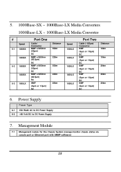
Management Module 7-1 Management module for the Chassis System (manage/monitor chassis status via console port or Ethernet port with SNMP software) 18 5. 1000Base-SX ~ 1000Base-LX Media Converters 1000Base-LX ~ 1000Base-LX Media Converter # Speed 5-1 1000SX 1000SX 5-2 1000SX 1000SX 5-3 1000LX Port One Cable / Connector MMF of 850nm (50µ m) SC MMF of 850nm (62.5µ m) SC MMF of 850nm (50µ m) SC MMF of 850nm...
Management Module 7-1 Management module for the Chassis System (manage/monitor chassis status via console port or Ethernet port with SNMP software) 18 5. 1000Base-SX ~ 1000Base-LX Media Converters 1000Base-LX ~ 1000Base-LX Media Converter # Speed 5-1 1000SX 1000SX 5-2 1000SX 1000SX 5-3 1000LX Port One Cable / Connector MMF of 850nm (50µ m) SC MMF of 850nm (62.5µ m) SC MMF of 850nm (50µ m) SC MMF of 850nm...


