Data Sheet
Page 1
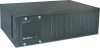
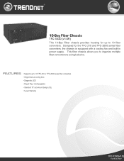
... a single device. This fiber chassis allows you to organize multiple fiber converters to 10 fiber converters. 10-Bay Fiber Chassis TFC-1000 (v1.0R) This 10-Bay Fiber chassis provides housing for the TFC-210 and TFC-2000 series fiber converters, the chassis is equipped with a cooling fan and built-in power supply. Hot-Swappable • Standard 19" rack-mount design...
... a single device. This fiber chassis allows you to organize multiple fiber converters to 10 fiber converters. 10-Bay Fiber Chassis TFC-1000 (v1.0R) This 10-Bay Fiber chassis provides housing for the TFC-210 and TFC-2000 series fiber converters, the chassis is equipped with a cooling fan and built-in power supply. Hot-Swappable • Standard 19" rack-mount design...
Data Sheet
Page 2
Copyright © TRENDnet. Information provided in this document pertain to change at any time, without notice. All Rights Reserved. 10-Bay Fiber Chassis TFC-1000 (v1.0R) SPECIFICATIONS Hardware Interface Diagnostic LED Power Power Consumption Dimensions Weight Temperature Humidity Certification • 10-Bay of their respective holders. For the most recent product information please visit http://www.trendnet.com. Other Brands and product names are trademarks...
Copyright © TRENDnet. Information provided in this document pertain to change at any time, without notice. All Rights Reserved. 10-Bay Fiber Chassis TFC-1000 (v1.0R) SPECIFICATIONS Hardware Interface Diagnostic LED Power Power Consumption Dimensions Weight Temperature Humidity Certification • 10-Bay of their respective holders. For the most recent product information please visit http://www.trendnet.com. Other Brands and product names are trademarks...

Quick Installation Guide
Page 2
Hardware Installation 3 LLCF Function 9 Technical Specifications 11 Troubleshooting 13 Version 02.13.2007 Product Details 2 3. TTaabblleeofoCfoCntoenntstents English 1 1. Before You Start 1 2.
Hardware Installation 3 LLCF Function 9 Technical Specifications 11 Troubleshooting 13 Version 02.13.2007 Product Details 2 3. TTaabblleeofoCfoCntoenntstents English 1 1. Before You Start 1 2.
Quick Installation Guide
Page 3
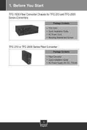
1. Before You Start TFC-1000 Fiber Converter Chassis for TFC-210 and TFC-2000 Series Converters: Package Contents TFC-1000 Quick Installation Guide AC Power Cord Mounting Bracket and Screws TFC-210 or TFC-2000 Series Fiber Converter: Package Contents Fiber Converter Quick Installation Guide AC Power Supply (9V DC, 700mA) 1 English
1. Before You Start TFC-1000 Fiber Converter Chassis for TFC-210 and TFC-2000 Series Converters: Package Contents TFC-1000 Quick Installation Guide AC Power Cord Mounting Bracket and Screws TFC-210 or TFC-2000 Series Fiber Converter: Package Contents Fiber Converter Quick Installation Guide AC Power Supply (9V DC, 700mA) 1 English
Quick Installation Guide
Page 4
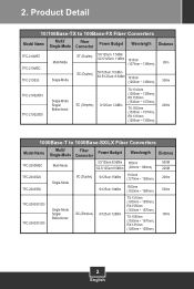
Product Detail 10/100Base-TX to 100Base-FX Fiber Converters Model Name Multi/ Fiber Single-Mode Connector Power Budget Wavelength Distance TFC-210MST TFC-210MSC TFC-210S30 Multi-Mode Single-Mode ST (Duplex) 50/125um: 7.5dBm 62.5/125um: 11dBm 1310nm (1270nm ~ 1380nm) SC (Duplex) 50/125um: 8.5dBm 62.5/125um: 8.5dBm 1310nm (1260nm ~ 1360nm) 2Km 30Km TFC-210S20D3 TFC-210S20D5 Single-Mode Single/ Bidirectional...
Product Detail 10/100Base-TX to 100Base-FX Fiber Converters Model Name Multi/ Fiber Single-Mode Connector Power Budget Wavelength Distance TFC-210MST TFC-210MSC TFC-210S30 Multi-Mode Single-Mode ST (Duplex) 50/125um: 7.5dBm 62.5/125um: 11dBm 1310nm (1270nm ~ 1380nm) SC (Duplex) 50/125um: 8.5dBm 62.5/125um: 8.5dBm 1310nm (1260nm ~ 1360nm) 2Km 30Km TFC-210S20D3 TFC-210S20D5 Single-Mode Single/ Bidirectional...
Quick Installation Guide
Page 5
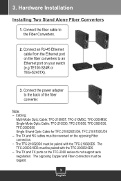
... TFC-2000 series do not support auto negotiation. Connect an RJ-45 Ethernet cable from the Ethernet port on the fiber converters to an Ethernet port on your switch (e.g TE100-S24R or TEG-S240TX). 3. Cabling: Multi-Mode Optic Cable: TFC-210MST, TFC-210MSC, TFC-2000MSC Single-Mode Optic Cable: TFC-210S30, TFC-210S50, TFC-2000S30, TFC-2000S50 Single Strand Optic Cable for TFC-210S20D3/D5, TFC-210S10D3/D5 - 3. The TFC-2000S10D3 must be paired with the TFC-2000S10D5. - Hardware Installation Installing...
... TFC-2000 series do not support auto negotiation. Connect an RJ-45 Ethernet cable from the Ethernet port on the fiber converters to an Ethernet port on your switch (e.g TE100-S24R or TEG-S240TX). 3. Cabling: Multi-Mode Optic Cable: TFC-210MST, TFC-210MSC, TFC-2000MSC Single-Mode Optic Cable: TFC-210S30, TFC-210S50, TFC-2000S30, TFC-2000S50 Single Strand Optic Cable for TFC-210S20D3/D5, TFC-210S10D3/D5 - 3. The TFC-2000S10D3 must be paired with the TFC-2000S10D5. - Hardware Installation Installing...
Quick Installation Guide
Page 6
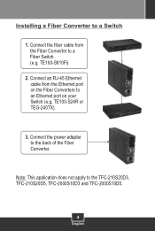
Installing a Fiber Converter to an Ethernet port on the Fiber Converters to a Switch 1. Connect an RJ-45 Ethernet cable from the Fiber Converter to the TFC-210S20D3, TFC-210S20D5, TFC-2000S10D3 and TFC-2000S10D5. 4 English Note: This application does not apply to a Fiber Switch (e.g. Connect the fiber cable from the Ethernet port on your Switch (e.g. Connect the power adapter to the back of the Fiber Converter. TE100-S810Fi) 2. TE100-S24R or TEG-240TX). 3.
Installing a Fiber Converter to an Ethernet port on the Fiber Converters to a Switch 1. Connect an RJ-45 Ethernet cable from the Fiber Converter to the TFC-210S20D3, TFC-210S20D5, TFC-2000S10D3 and TFC-2000S10D5. 4 English Note: This application does not apply to a Fiber Switch (e.g. Connect the fiber cable from the Ethernet port on your Switch (e.g. Connect the power adapter to the back of the Fiber Converter. TE100-S810Fi) 2. TE100-S24R or TEG-240TX). 3.
Quick Installation Guide
Page 7
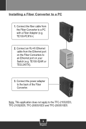
Connect an RJ-45 Ethernet cable from the Fiber Converter to a PC with a Fiber Adapter (e.g. Connect the power adapter to the TFC-210S20D3, TFC-210S20D5, TFC-2000S10D3 and TFC-2000S10D5. 5 English Note: This application does not apply to the back of the Fiber Converter. TE100-PCIFX+) 2. TE100-S24R or TEG-240TX). 3. Connect the fiber cable from the Ethernet port on your Switch (e.g. Installing a Fiber Converter to an Ethernet port on the Fiber Converters to a PC 1.
Connect an RJ-45 Ethernet cable from the Fiber Converter to a PC with a Fiber Adapter (e.g. Connect the power adapter to the TFC-210S20D3, TFC-210S20D5, TFC-2000S10D3 and TFC-2000S10D5. 5 English Note: This application does not apply to the back of the Fiber Converter. TE100-PCIFX+) 2. TE100-S24R or TEG-240TX). 3. Connect the fiber cable from the Ethernet port on your Switch (e.g. Installing a Fiber Converter to an Ethernet port on the Fiber Converters to a PC 1.

Quick Installation Guide
Page 8
Using a screwdriver unscrew the Module Bay Cover from the desired bay on the Chassis and remove the cover. Install the Fiber Converter with the fiber port near the bottom of Fiber Converter. 3. Slide the Fiber Converter into an available slot. Attach the Mounting Bracket to secure the Fiber Converter. 6 English Installing Fiber Converter in the future. 2. Then fasten the screws to the side of the Chassis. Save the screw and cover in case you need to cover up the module bay in a Chassis 1.
Using a screwdriver unscrew the Module Bay Cover from the desired bay on the Chassis and remove the cover. Install the Fiber Converter with the fiber port near the bottom of Fiber Converter. 3. Slide the Fiber Converter into an available slot. Attach the Mounting Bracket to secure the Fiber Converter. 6 English Installing Fiber Converter in the future. 2. Then fasten the screws to the side of the Chassis. Save the screw and cover in case you need to cover up the module bay in a Chassis 1.

Quick Installation Guide
Page 9
Align the bracket to the screw holes on each side), and secure them with the provided screws. 2. Carefully position the Chassis onto the rack. Rack Mount The Chassis can be mounted in an EIA standard-size, 19-inch rack, which can be placed in a wiring closet with the equipment rack to mount the Chassis. 7 English Attach the mounting brackets to the Chassis's front panel (one on the rack, then use the screws provided with other equipment. 1.
Align the bracket to the screw holes on each side), and secure them with the provided screws. 2. Carefully position the Chassis onto the rack. Rack Mount The Chassis can be mounted in an EIA standard-size, 19-inch rack, which can be placed in a wiring closet with the equipment rack to mount the Chassis. 7 English Attach the mounting brackets to the Chassis's front panel (one on the rack, then use the screws provided with other equipment. 1.
Quick Installation Guide
Page 10
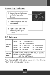
... Enable OFF LLCF Disable Switch 4 ON Pure Mode OFF Switch Mode Switch 1: ON: TX LLCF Enable OFF: TX LLCF (Disable) TFC-2000 Switch 2: ON: Fiber LLCF Enable series OFF: Fiber LLCF (Disable) After changing the DIP Switch settings power cycle the Fiber Converter LLCF stands for Link Loss Carry Forward 8 English Flip the switch to the ON position to the back of the Chassis. 2. Connect the supplied power cord to power up the Chassis. Connecting the Power...
... Enable OFF LLCF Disable Switch 4 ON Pure Mode OFF Switch Mode Switch 1: ON: TX LLCF Enable OFF: TX LLCF (Disable) TFC-2000 Switch 2: ON: Fiber LLCF Enable series OFF: Fiber LLCF (Disable) After changing the DIP Switch settings power cycle the Fiber Converter LLCF stands for Link Loss Carry Forward 8 English Flip the switch to the ON position to the back of the Chassis. 2. Connect the supplied power cord to power up the Chassis. Connecting the Power...
Quick Installation Guide
Page 11
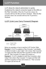
... Cable 1 Converter 1 Media Converter 2 Cable 4 Copper Cable Fiber Cable Below are examples on how to read the LLCF Function Table: Example 1: If LLCF is enabled on Fiber Converter 1 and disable on Media Converter 2, when Cable 1 link is down , Fiber Converter 1's Copper and Fiber LED and Fiber Converter 2's Fiber LED will force the fiber port link to shutdown. LLCF Function LLCF allows the network administrator to quickly troubleshoot the network connection...
... Cable 1 Converter 1 Media Converter 2 Cable 4 Copper Cable Fiber Cable Below are examples on how to read the LLCF Function Table: Example 1: If LLCF is enabled on Fiber Converter 1 and disable on Media Converter 2, when Cable 1 link is down , Fiber Converter 1's Copper and Fiber LED and Fiber Converter 2's Fiber LED will force the fiber port link to shutdown. LLCF Function LLCF allows the network administrator to quickly troubleshoot the network connection...
Quick Installation Guide
Page 12
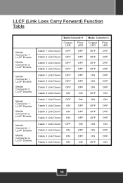
... Carry Forward) Function Table Media Converter 1 LLCF Enable Media Converter 2 LLCF Enable Media Converter 1 LLCF Enable Media Converter 2 LLCF Disable Media Converter 1 LLCF Disable Media Converter 2 LLCF Enable Media Converter 1 LLCF Disable Media Converter 2 LLCF Disable Media Converter 1 Copper LED Fiber LED Cable 1 Link Down OFF OFF Media Converter 2 Copper LED Fiber LED OFF OFF Cable 2 Link Down OFF OFF OFF OFF Cable 3 Link Down OFF OFF OFF OFF Cable 4 Link...
... Carry Forward) Function Table Media Converter 1 LLCF Enable Media Converter 2 LLCF Enable Media Converter 1 LLCF Enable Media Converter 2 LLCF Disable Media Converter 1 LLCF Disable Media Converter 2 LLCF Enable Media Converter 1 LLCF Disable Media Converter 2 LLCF Disable Media Converter 1 Copper LED Fiber LED Cable 1 Link Down OFF OFF Media Converter 2 Copper LED Fiber LED OFF OFF Cable 2 Link Down OFF OFF OFF OFF Cable 3 Link Down OFF OFF OFF OFF Cable 4 Link...
Quick Installation Guide
Page 13
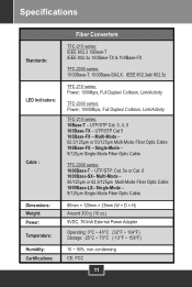
..., Link/Activity TFC-2000 series: Power; 1000Mbps, Full Duplex/ Collision, Link/Activity TFC-210 series: 10Base-T - Multi-Mode - 50/125ìm or 62.5/125ìm Multi-Mode Fiber Optic Cable 1000Base-LX- Single-Mode - 9/125ìm Single-Mode Fiber Optic Cable TFC-2000 series: 1000Base-T - Single-Mode - 9/125ìm Single-Mode Fiber Optic Cable 85mm × 125mm × 25mm (W × D × H) Around 300 g (10 oz.) 9VDC, 700mA External Power Adapter Operating...
..., Link/Activity TFC-2000 series: Power; 1000Mbps, Full Duplex/ Collision, Link/Activity TFC-210 series: 10Base-T - Multi-Mode - 50/125ìm or 62.5/125ìm Multi-Mode Fiber Optic Cable 1000Base-LX- Single-Mode - 9/125ìm Single-Mode Fiber Optic Cable TFC-2000 series: 1000Base-T - Single-Mode - 9/125ìm Single-Mode Fiber Optic Cable 85mm × 125mm × 25mm (W × D × H) Around 300 g (10 oz.) 9VDC, 700mA External Power Adapter Operating...
Quick Installation Guide
Page 14
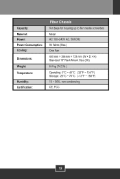
Capacity: Material: Power: Power Consumption: Cooling: Dimensions: Weight: Temperature: Humidity: Certification: Fiber Chassis Ten bays for housing up to Ten media converters Metal AC 100~240V AC, 50/60Hz 90 Watts (Max) One Fan 440 mm × 266mm × 133 mm (W × D × H) Standard 19" Rack Mount Size (3U) 6.4 kg (14.2 lb.) Operating: 0°C ~ 40°C (32°F ~ 104°F) Storage: -25°C ~ 70°C (-13°F ~ 158°F) 10 ~ 90%, non-condensing CE, FCC 12
Capacity: Material: Power: Power Consumption: Cooling: Dimensions: Weight: Temperature: Humidity: Certification: Fiber Chassis Ten bays for housing up to Ten media converters Metal AC 100~240V AC, 50/60Hz 90 Watts (Max) One Fan 440 mm × 266mm × 133 mm (W × D × H) Standard 19" Rack Mount Size (3U) 6.4 kg (14.2 lb.) Operating: 0°C ~ 40°C (32°F ~ 104°F) Storage: -25°C ~ 70°C (-13°F ~ 158°F) 10 ~ 90%, non-condensing CE, FCC 12
Quick Installation Guide
Page 15
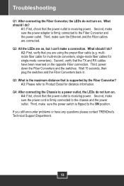
... position. Third, make a connection. What should I do not turn on the opposite Fiber connection. single-mode fiber cables for multi-mode converters; Troubleshooting Q1: After connecting the Fiber Converter, the LEDs do ? A1: First, check that the TX and RX cables have any questions please contact TRENDnet's Technical Support Department. 13 Third, power down the Fiber Converters and the switches. Second, make sure the power adapter is supported by the...
... position. Third, make a connection. What should I do not turn on the opposite Fiber connection. single-mode fiber cables for multi-mode converters; Troubleshooting Q1: After connecting the Fiber Converter, the LEDs do ? A1: First, check that the TX and RX cables have any questions please contact TRENDnet's Technical Support Department. 13 Third, power down the Fiber Converters and the switches. Second, make sure the power adapter is supported by the...
Quick Installation Guide
Page 16
... software, firmware, information, or memory data of TRENDnet. Products returned to TRENDnet must be responsible for the following lengths of time from the date of the purchase. All products that are no user serviceable parts inside the product. This warranty is voided if (i) the product has been modified or repaired by any unauthorized service center, (ii) the product was subject to accident, abuse, or improper use and service...
... software, firmware, information, or memory data of TRENDnet. Products returned to TRENDnet must be responsible for the following lengths of time from the date of the purchase. All products that are no user serviceable parts inside the product. This warranty is voided if (i) the product has been modified or repaired by any unauthorized service center, (ii) the product was subject to accident, abuse, or improper use and service...
Quick Installation Guide
Page 17
Note: AC/DC Power Adapter, Cooling Fan, Cables and Power Supply carry a 1-Year Warranty 15 WARRANTIES EXCLUSIVE: IF THE TRENDNET PRODUCT DOES NOT OPERATE AS WARRANTED ABOVE, THE CUSTOMER'S SOLE REMEDY SHALL BE, AT TRENDNET'S OPTION, REPAIR OR REPLACEMENT. TRENDNET SHALL NOT BE LIABLE UNDER THIS WARRANTY IF ITS TESTING AND EXAMINATION DISCLOSE THAT THE ALLEGED DEFECT IN THE PRODUCT DOES NOT EXIST OR...
Note: AC/DC Power Adapter, Cooling Fan, Cables and Power Supply carry a 1-Year Warranty 15 WARRANTIES EXCLUSIVE: IF THE TRENDNET PRODUCT DOES NOT OPERATE AS WARRANTED ABOVE, THE CUSTOMER'S SOLE REMEDY SHALL BE, AT TRENDNET'S OPTION, REPAIR OR REPLACEMENT. TRENDNET SHALL NOT BE LIABLE UNDER THIS WARRANTY IF ITS TESTING AND EXAMINATION DISCLOSE THAT THE ALLEGED DEFECT IN THE PRODUCT DOES NOT EXIST OR...

Quick Installation Guide
Page 18
Waste electrical and electronic products must accept any interference received. Please recycle where facilities exist. Check with FCC and CE Rules. El uso de un adaptador distinto al mencionado puede producir daños fisicos y/o daños al...ón. Including interference that may not cause harmful interference. (2) This device must not be disposed of with household waste. SUCH MODIFICATIONS COULD VOID THE USER'S AUTHORITY TO OPERATE THE EQUIPMENT. Operation is subject to comply with you Local Authority or Retailer for recycling advice. ADVERTENCIA En todos nuestros equipos se...
Waste electrical and electronic products must accept any interference received. Please recycle where facilities exist. Check with FCC and CE Rules. El uso de un adaptador distinto al mencionado puede producir daños fisicos y/o daños al...ón. Including interference that may not cause harmful interference. (2) This device must not be disposed of with household waste. SUCH MODIFICATIONS COULD VOID THE USER'S AUTHORITY TO OPERATE THE EQUIPMENT. Operation is subject to comply with you Local Authority or Retailer for recycling advice. ADVERTENCIA En todos nuestros equipos se...

Quick Installation Guide
Page 19
.../7 Francais/Deutsch - 11am-8pm, Monday - TRENDnet. TRENDnet Technical Support Toll Free Telephone: 1(866) 845-3673 US . UK) Toll Free Telephone: +00800 60 76 76 67 English/Espanol - 24/7 Francais/Deutsch - 11am-8pm, Monday - Canada 24/7 Tech Support Europe (Germany . Go to register your product online. Italy . All Rights Reserved. Friday MET Product Warranty Registration Please take a moment to...
.../7 Francais/Deutsch - 11am-8pm, Monday - TRENDnet. TRENDnet Technical Support Toll Free Telephone: 1(866) 845-3673 US . UK) Toll Free Telephone: +00800 60 76 76 67 English/Espanol - 24/7 Francais/Deutsch - 11am-8pm, Monday - Canada 24/7 Tech Support Europe (Germany . Go to register your product online. Italy . All Rights Reserved. Friday MET Product Warranty Registration Please take a moment to...


