Data Sheet
Page 1
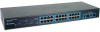
... upgrade to -use and enhances network security. TEG-224WS supports web browser configuration allowing Network Administrators to configure speed, VLAN, QoS, Trunking and Mirroring down to the port level. TEG-224WS rev:02.17.2006 26-port 10/100/1000Mbps Gigabit Web-Based Smart Switch TEG-224WS TRENDnet's TEG-224WS 26-port 10/100/1000Mbps Web-Based Smart Switch is powerful, easy-to Fast Ethernet by changing...
... upgrade to -use and enhances network security. TEG-224WS supports web browser configuration allowing Network Administrators to configure speed, VLAN, QoS, Trunking and Mirroring down to the port level. TEG-224WS rev:02.17.2006 26-port 10/100/1000Mbps Gigabit Web-Based Smart Switch TEG-224WS TRENDnet's TEG-224WS 26-port 10/100/1000Mbps Web-Based Smart Switch is powerful, easy-to Fast Ethernet by changing...
Data Sheet
Page 2
...-A NETWORKING SOLUTIONS RELATED PRODUCTS TEG-224WS 26-Port 10/100/1000Mbps Gigabit Web-Based Smart Switch(Rack Mount) TEG-S18TXE TEG-S80TXD 9-Port (8 10/100, 1 10/100/1000) Copper Gigabit Mini Switch 8-Port Copper Gigabit Switch ORDERING INFORMATION 3135 Kashiwa Street,Torrance, CA 90505 USA Tel: 1-310-891-1100 Fax: 310-891-1111 Web: www.trendnet.com Email: sales@trendnet.com To Order Please Call...
...-A NETWORKING SOLUTIONS RELATED PRODUCTS TEG-224WS 26-Port 10/100/1000Mbps Gigabit Web-Based Smart Switch(Rack Mount) TEG-S18TXE TEG-S80TXD 9-Port (8 10/100, 1 10/100/1000) Copper Gigabit Mini Switch 8-Port Copper Gigabit Switch ORDERING INFORMATION 3135 Kashiwa Street,Torrance, CA 90505 USA Tel: 1-310-891-1100 Fax: 310-891-1111 Web: www.trendnet.com Email: sales@trendnet.com To Order Please Call...

User's Guide
Page 5
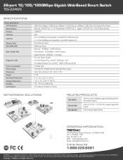
TABLE OF CONTENT About This Guide 1 Purpose 1 Terms/Usage 1 Introduction 3 Gigabit Ethernet Technology 3 Fast Ethernet Technology 4 Switching Technology 5 VLAN (Virtual Local Area Network 6 Features 6 Unpacking and Installation 9 Unpacking 9 Installation 9 Rack Mounting 10 Connecting Network Cable 11 AC Power 11 Identifying External Components 13 Front Panel 13 Rear Panel 14 Understanding LED Indicators 15 Power and System LEDs 15 Ports 1~24 10/100M Status LEDs 16 Ports 25~26 Gigabit Status LEDs 16 Configuration 18 i
TABLE OF CONTENT About This Guide 1 Purpose 1 Terms/Usage 1 Introduction 3 Gigabit Ethernet Technology 3 Fast Ethernet Technology 4 Switching Technology 5 VLAN (Virtual Local Area Network 6 Features 6 Unpacking and Installation 9 Unpacking 9 Installation 9 Rack Mounting 10 Connecting Network Cable 11 AC Power 11 Identifying External Components 13 Front Panel 13 Rear Panel 14 Understanding LED Indicators 15 Power and System LEDs 15 Ports 1~24 10/100M Status LEDs 16 Ports 25~26 Gigabit Status LEDs 16 Configuration 18 i
User's Guide
Page 6
Installing the Web Management Utility 18 Discovery List 19 Monitor List 20 Device Setting 22 Toolbar 23 Configuring the Switch 24 Login 25 Setup Menu 27 Configuring Setup Setting 28 Port Settings 28 VLAN Settings (Virtual Local Area Network 30 Trunk Setting 31 Mirror Setting 31 Device Status 32 System Setting 32 Trap Setting 33 Set Password 34 Backup Setting 34 Reset Setting 35 Logout 35 Technical Specifications 37 ii
Installing the Web Management Utility 18 Discovery List 19 Monitor List 20 Device Setting 22 Toolbar 23 Configuring the Switch 24 Login 25 Setup Menu 27 Configuring Setup Setting 28 Port Settings 28 VLAN Settings (Virtual Local Area Network 30 Trunk Setting 31 Mirror Setting 31 Device Status 32 System Setting 32 Trap Setting 33 Set Password 34 Backup Setting 34 Reset Setting 35 Logout 35 Technical Specifications 37 ii

User's Guide
Page 7
ABOUT THIS GUIDE Congratulations on your 24+2G-Port 10/100/1000Mbps Gigabit Ethernet Web Smart Switch, and "switch" (first letter lower case) refers to your purchase of the 24+2G-Port 10/100/1000Mbps Gigabit Ethernet Web Smart Switch. This device integrates 1000Mbps Gigabit Ethernet, 100Mbps Fast Ethernet and 10Mbps Ethernet network capabilities in a highly flexible package. Purpose This guide...
ABOUT THIS GUIDE Congratulations on your 24+2G-Port 10/100/1000Mbps Gigabit Ethernet Web Smart Switch, and "switch" (first letter lower case) refers to your purchase of the 24+2G-Port 10/100/1000Mbps Gigabit Ethernet Web Smart Switch. This device integrates 1000Mbps Gigabit Ethernet, 100Mbps Fast Ethernet and 10Mbps Ethernet network capabilities in a highly flexible package. Purpose This guide...
User's Guide
Page 9
... busses get faster and more users use applications that generate more traffic. Since it is an extension of time. 3 Gigabit Ethernet Technology Gigabit Ethernet is compatible with a tenfold increase in the same amount of IEEE 802.3 Ethernet utilizing the same packet structure, ... are able to perform 10 times the number of the 24+2G-Port 10/100/1000Mbps Gigabit Ethernet Web Smart Switch and some background information about Ethernet/Fast Ethernet/Gigabit Ethernet switching technology. Upgrading key components, such as your subnets. INTRODUCTION This chapter describes the features of...
... busses get faster and more users use applications that generate more traffic. Since it is an extension of time. 3 Gigabit Ethernet Technology Gigabit Ethernet is compatible with a tenfold increase in the same amount of IEEE 802.3 Ethernet utilizing the same packet structure, ... are able to perform 10 times the number of the 24+2G-Port 10/100/1000Mbps Gigabit Ethernet Web Smart Switch and some background information about Ethernet/Fast Ethernet/Gigabit Ethernet switching technology. Upgrading key components, such as your subnets. INTRODUCTION This chapter describes the features of...

User's Guide
Page 10
...upgrade and takes advantage of desktop computing applications are fueling the need for the next generation of today and tomorrow's rapidly improving switching and routing internetworking technologies. And with expected advances in the coming years in hardware, software, and personnel training. 4 A number...importance of LANs and the increasing complexity of the existing investment in silicon technology and digital signal processing that will enable Gigabit Ethernet to eventually operate over unshielded twisted-pair (UTP) cabling, outfitting your network with the ability to provide greater...
...upgrade and takes advantage of desktop computing applications are fueling the need for the next generation of today and tomorrow's rapidly improving switching and routing internetworking technologies. And with expected advances in the coming years in hardware, software, and personnel training. 4 A number...importance of LANs and the increasing complexity of the existing investment in silicon technology and digital signal processing that will enable Gigabit Ethernet to eventually operate over unshielded twisted-pair (UTP) cabling, outfitting your network with the ability to provide greater...
User's Guide
Page 11
... doing this the total network capacity is multiplied, while still maintaining the same network cabling and adapter cards. Switching LAN technology is a marked improvement over the previous generation of the Ethernet protocol transmitting among connected Ethernet or Fast Ethernet ...and maintenance required make routers relatively impractical. Routers have also been used to segment local area networks, but the cost of switching technology. A switch bridges Ethernet packets at the MAC address level of network bridges, which were characterized by dividing a local area network into ...
... doing this the total network capacity is multiplied, while still maintaining the same network cabling and adapter cards. Switching LAN technology is a marked improvement over the previous generation of the Ethernet protocol transmitting among connected Ethernet or Fast Ethernet ...and maintenance required make routers relatively impractical. Routers have also been used to segment local area networks, but the cost of switching technology. A switch bridges Ethernet packets at the MAC address level of network bridges, which were characterized by dividing a local area network into ...

User's Guide
Page 12
...utility includes: Security, Security is increased with the reduction of using faster switching instead. Features ‹ 24×10/100Mbps Auto-negotiation Fast Ethernet RJ45 ports ‹ 2×10/100/1000Mbps Auto-negotiation Gigabit RJ45 ports ‹ All RJ45 ports support auto MDI/MDIX, so ... Full/half duplex transfer mode for 10/100Mbps RJ45 port ‹ Full duplex transfer mode for Gigabit port ‹ Wire speed reception and transmission ‹ Store-and-Forward switching scheme capability to reduce latency and need of expensive routers. The primary utility of opportunity in the...
...utility includes: Security, Security is increased with the reduction of using faster switching instead. Features ‹ 24×10/100Mbps Auto-negotiation Fast Ethernet RJ45 ports ‹ 2×10/100/1000Mbps Auto-negotiation Gigabit RJ45 ports ‹ All RJ45 ports support auto MDI/MDIX, so ... Full/half duplex transfer mode for 10/100Mbps RJ45 port ‹ Full duplex transfer mode for Gigabit port ‹ Wire speed reception and transmission ‹ Store-and-Forward switching scheme capability to reduce latency and need of expensive routers. The primary utility of opportunity in the...

User's Guide
Page 15
... 10/100/1000Mbps Gigabit Ethernet Web Smart Switch ‹ One AC power cord, suitable for your area's electrical power connections ‹ Four rubber feet to sunlight. 9 Install the Switch in a fairly cool and dry place. The carton should contain the following pointers: Install the Switch in a site ...free from strong electromagnetic field generators (such as motors), vibration, dust, and direct exposure to be used for shock cushioning ‹ Screws and two mounting brackets ‹ CD-Rom with Web Management Utility and User's Guide...
... 10/100/1000Mbps Gigabit Ethernet Web Smart Switch ‹ One AC power cord, suitable for your area's electrical power connections ‹ Four rubber feet to sunlight. 9 Install the Switch in a fairly cool and dry place. The carton should contain the following pointers: Install the Switch in a site ...free from strong electromagnetic field generators (such as motors), vibration, dust, and direct exposure to be used for shock cushioning ‹ Screws and two mounting brackets ‹ CD-Rom with Web Management Utility and User's Guide...

User's Guide
Page 16
... with the provided screws. The rubber feet cushion the hub and protect the hub case from scratching. Mount the Switch in an EIA standard-size equipment rack. When installing the Switch on a level surface, attach the rubber feet to mount each side), and secure them with other equipment. Figure... 2. Install the Switch on rack installation, see the next section, Rack Mounting. Rack Mounting The switch can be mounted in an EIA standard-size, 19-inch rack, which can support its weight, or in...
... with the provided screws. The rubber feet cushion the hub and protect the hub case from scratching. Mount the Switch in an EIA standard-size equipment rack. When installing the Switch on a level surface, attach the rubber feet to mount each side), and secure them with other equipment. Figure... 2. Install the Switch on rack installation, see the next section, Rack Mounting. Rack Mounting The switch can be mounted in an EIA standard-size, 19-inch rack, which can support its weight, or in...

User's Guide
Page 17
...the AC power supply 100-240V AC, 50-60 Hz. These RJ45 ports are using a standard or crossover RJ45 cable. The Switch also supports 2-Ports 1000Mbps Gigabit Ethernet that runs in Auto-negotiation mode and 10Mbps Ethernet or 100Mbps Fast Ethernet that without having any or all LAN segment cables ...connected. 11 The Switch can auto transform to MDI-II or MDI-X type, so you are Auto-MDI type port. The switch's power supply ...
...the AC power supply 100-240V AC, 50-60 Hz. These RJ45 ports are using a standard or crossover RJ45 cable. The Switch also supports 2-Ports 1000Mbps Gigabit Ethernet that runs in Auto-negotiation mode and 10Mbps Ethernet or 100Mbps Fast Ethernet that without having any or all LAN segment cables ...connected. 11 The Switch can auto transform to MDI-II or MDI-X type, so you are Auto-MDI type port. The switch's power supply ...

User's Guide
Page 19
...or 100Mbps, and can operate in half-duplex mode for 10/100/1000Mbps. Front panel of 24+2G-port Gigabit Ethernet Switch LED Indicator: Comprehensive LED indicators display the status of the switch and the network (see the LED Indicators chapter below shows the front panels of the... Switch. duplex transfer modes. Gigabit Ethernet Ports (Port 25~26): The Switch is equipped with two Gigabit twisted pair ports, supported auto negotiable 10/100/...
...or 100Mbps, and can operate in half-duplex mode for 10/100/1000Mbps. Front panel of 24+2G-port Gigabit Ethernet Switch LED Indicator: Comprehensive LED indicators display the status of the switch and the network (see the LED Indicators chapter below shows the front panels of the... Switch. duplex transfer modes. Gigabit Ethernet Ports (Port 25~26): The Switch is equipped with two Gigabit twisted pair ports, supported auto negotiable 10/100/...
User's Guide
Page 20
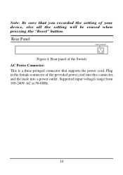
Supported input voltages range from 100-240V AC at 50-60Hz. 14 Plug in the female connector of your device, else all the setting will be erased when pressing the "Reset" button. Note: Be sure that supports the power cord. Rear Panel Figure 4. Rear panel of the Switch AC Power Connector: This is a three-pronged connector that you recorded the setting of the provided power cord into this connector, and the male into a power outlet.
Supported input voltages range from 100-240V AC at 50-60Hz. 14 Plug in the female connector of your device, else all the setting will be erased when pressing the "Reset" button. Note: Be sure that supports the power cord. Rear Panel Figure 4. Rear panel of the Switch AC Power Connector: This is a three-pronged connector that you recorded the setting of the provided power cord into this connector, and the male into a power outlet.

User's Guide
Page 21
On/Off : The CPU is not working , the System LED is blinking. UNDERSTANDING LED INDICATORS The front panel LEDs provides instant status feedback, and, helps monitor and troubleshoot when needed. SYSTEM: Management Indicator Blinking : When the CPU is receiving power. Off : When the Power turns off or the power cord has improper connection. Figure 5. LED indicators of the Switch Power and System LEDs POWER: Power Indicator On : When the Power LED lights on, the Switch is working . 15
On/Off : The CPU is not working , the System LED is blinking. UNDERSTANDING LED INDICATORS The front panel LEDs provides instant status feedback, and, helps monitor and troubleshoot when needed. SYSTEM: Management Indicator Blinking : When the CPU is receiving power. Off : When the Power turns off or the power cord has improper connection. Figure 5. LED indicators of the Switch Power and System LEDs POWER: Power Indicator On : When the Power LED lights on, the Switch is working . 15
User's Guide
Page 24
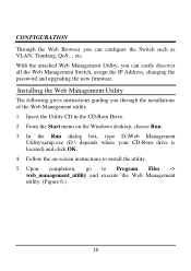
... Utility CD in the CD-Rom Drive. 2. CONFIGURATION Through the Web Browser you can easily discover all the Web Management Switch, assign the IP Address, changing the password and upgrading the new firmware. With the attached Web Management Utility, you through the installations of the Web Management utility. 1. etc. Follow the on the Windows desktop...
... Utility CD in the CD-Rom Drive. 2. CONFIGURATION Through the Web Browser you can easily discover all the Web Management Switch, assign the IP Address, changing the password and upgrading the new firmware. With the attached Web Management Utility, you through the installations of the Web Management utility. 1. etc. Follow the on the Windows desktop...
User's Guide
Page 27
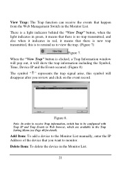
.... (Figure 8) The symbol " " represents the trap signal arise, this symbol will disappear after you want to monitor. Figure 8. Note: In order to receive Trap information, switch has to view the trap. (Figure 7) Figure 7. Add Item: To add a device to the Monitor List manually, enter the IP Address of the device that... and click on the event record. When the "View Trap" button is to remind us to be configured with Trap IP and Trap Events in Web browser, which are available in the Trap Setting Menu (see Page 40 for detail). View Trap: The Trap function can receive the events that happen...
.... (Figure 8) The symbol " " represents the trap signal arise, this symbol will disappear after you want to monitor. Figure 8. Note: In order to receive Trap information, switch has to view the trap. (Figure 7) Figure 7. Add Item: To add a device to the Monitor List manually, enter the IP Address of the device that... and click on the event record. When the "View Trap" button is to remind us to be configured with Trap IP and Trap Events in Web browser, which are available in the Trap Setting Menu (see Page 40 for detail). View Trap: The Trap function can receive the events that happen...
User's Guide
Page 30
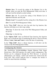
... the time of monitoring. Monitor Save As: To record the setting of monitoring the device. Configuring the Switch The 24+2G-Port 10/100/1000Mbps Gigabit Ethernet Web Smart Switch has a Web GUI interface for smart switch configuration. Exit: To exit the Web Management Utility. In the "Help TAB", there is About function, it will auto load the default...
... the time of monitoring. Monitor Save As: To record the setting of monitoring the device. Configuring the Switch The 24+2G-Port 10/100/1000Mbps Gigabit Ethernet Web Smart Switch has a Web GUI interface for smart switch configuration. Exit: To exit the Web Management Utility. In the "Help TAB", there is About function, it will auto load the default...

User's Guide
Page 31
... ‹ System Setting ‹ Device status Login Before you configure this device, note that when the Web Smart Switch is 255.255.255.0. For example, when the default network address of the default IP address of the Web Smart Switch is 192.168.0.1, then the manager PC should be set at 192.168.0.x (where x is a number...
... ‹ System Setting ‹ Device status Login Before you configure this device, note that when the Web Smart Switch is 255.255.255.0. For example, when the default network address of the default IP address of the Web Smart Switch is 192.168.0.1, then the manager PC should be set at 192.168.0.x (where x is a number...

User's Guide
Page 35
Flow Control: This setting determines whether or not the Switch will be change the port setting, click on the ID parameter to enter to the selected port to Disable. Figure 17. When the port is ...
Flow Control: This setting determines whether or not the Switch will be change the port setting, click on the ID parameter to enter to the selected port to Disable. Figure 17. When the port is ...
