
User Guide
Page 5
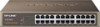
Package Contents The following contents should be found in your box: ¾ One TL-SF1016/TL-SF1016DS/TL-SF1024/TL-SF1024D/TL-SF1048 Switch ¾ One power cord ¾ This User Guide ¾ Mounting screws and two "L" planks Note: Make sure that the package contains the above items. If any of the listed items are damaged or missing, please contact with your distributor. TL-SF1016DS and TLSF1024D do not include mounting screws and two "L" planks. 1
Package Contents The following contents should be found in your box: ¾ One TL-SF1016/TL-SF1016DS/TL-SF1024/TL-SF1024D/TL-SF1048 Switch ¾ One power cord ¾ This User Guide ¾ Mounting screws and two "L" planks Note: Make sure that the package contains the above items. If any of the listed items are damaged or missing, please contact with your distributor. TL-SF1016DS and TLSF1024D do not include mounting screws and two "L" planks. 1

User Guide
Page 6
...standard upgrade to improve your network performance up to a 100Mbps network. Each port of the TL-SF1016 / TL-SF1016DS / TL-SF1024 / TL-SF1024D / TL-SF1048 supports auto MDI/MDI-X function, eliminating the need for monitoring power, link, activity, speed ¾ Rack-mountable steel case ¾ Internal power supply 2 MDI/... for half-duplex mode ¾ LED indicators for crossover cables or Uplink ports. The TL-SF1016/TL-SF1016DS/TL-SF1024/TL-SF1024D/TL-SF1048 16/24/48-port 10/100Mbps Fast Ethernet Switch provides you with IEEE802.3, IEEE802.3u standards ¾ 16/24/48 10/100Mbps Auto...
...standard upgrade to improve your network performance up to a 100Mbps network. Each port of the TL-SF1016 / TL-SF1016DS / TL-SF1024 / TL-SF1024D / TL-SF1048 supports auto MDI/MDI-X function, eliminating the need for monitoring power, link, activity, speed ¾ Rack-mountable steel case ¾ Internal power supply 2 MDI/... for half-duplex mode ¾ LED indicators for crossover cables or Uplink ports. The TL-SF1016/TL-SF1016DS/TL-SF1024/TL-SF1024D/TL-SF1048 16/24/48-port 10/100Mbps Fast Ethernet Switch provides you with IEEE802.3, IEEE802.3u standards ¾ 16/24/48 10/100Mbps Auto...
User Guide
Page 7
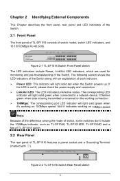
... as TL-SF1048, TL-SF1016DS, TL-SF1024D and a few of TL-SF1016 switch. 2.2 Rear Panel The rear panel of TL-SF1016 features a power socket and a Grounding Terminal (marked with an explanation of the Switch along with ). It flashes green when data is not lit, please check the power supply and connection. ¾ Link/Act LED: The LED indicates Link/Active...
... as TL-SF1048, TL-SF1016DS, TL-SF1024D and a few of TL-SF1016 switch. 2.2 Rear Panel The rear panel of TL-SF1016 features a power socket and a Grounding Terminal (marked with an explanation of the Switch along with ). It flashes green when data is not lit, please check the power supply and connection. ¾ Link/Act LED: The LED indicates Link/Active...

User Guide
Page 8
¾ Grounding Terminal: TL-SF1016 already comes with Ground Cable. You can also ground the Switch through the PE (Protecting Earth) cable of the input voltage. Please make sure the voltage of the power supply meets the requirement of AC cord ...or with Lightning Protection Mechanism. Note: Because of the difference among the mode of switch, some switches don't include the Grounding Terminal, such as TL-SF1048 and a few of the power cord here, and the male connector to Ground. ¾ AC Power Socket: Connect the female...
¾ Grounding Terminal: TL-SF1016 already comes with Ground Cable. You can also ground the Switch through the PE (Protecting Earth) cable of the input voltage. Please make sure the voltage of the power supply meets the requirement of AC cord ...or with Lightning Protection Mechanism. Note: Because of the difference among the mode of switch, some switches don't include the Grounding Terminal, such as TL-SF1048 and a few of the power cord here, and the male connector to Ground. ¾ AC Power Socket: Connect the female...

User Guide
Page 9
... the equipment. • Use only the power cord provided with all fittings. • Locate the Switch far from water and moisture sources, be easily connected. • Position the Switch away from strong electromagnetic field generators (such as motors), vibration, dust, and direct exposure to sunlight....well ventilated and unblocked. • Do not open or remove the cover of the Switch. 2) Location Requirements When you choose a location for the Switch, please follow these guidelines: • Install the Switch on a flat and stable surface that can be sure to the following before the ...
... the equipment. • Use only the power cord provided with all fittings. • Locate the Switch far from water and moisture sources, be easily connected. • Position the Switch away from strong electromagnetic field generators (such as motors), vibration, dust, and direct exposure to sunlight....well ventilated and unblocked. • Do not open or remove the cover of the Switch. 2) Location Requirements When you choose a location for the Switch, please follow these guidelines: • Install the Switch on a flat and stable surface that can be sure to the following before the ...

User Guide
Page 10
... the provided power cord. Caution: Please unplug the power cord before installing or removing the Switch. 3.2.1 Desktop Installation To install the Switch on the desktop. 3.2 Installation This Switch can be either installed on the standard 19-inch mountable rack or located on the desktop, ...please follow the instructions described below: 6 Figure 3-1 Attaching Rubber Feet 4) Upturn the Switch and connect it to the network devices while keep enough ventilation space around. 5) Connect the Switch to power source with all fittings. 2) Remove the adhesive backing papers from the rubber...
... the provided power cord. Caution: Please unplug the power cord before installing or removing the Switch. 3.2.1 Desktop Installation To install the Switch on the desktop. 3.2 Installation This Switch can be either installed on the standard 19-inch mountable rack or located on the desktop, ...please follow the instructions described below: 6 Figure 3-1 Attaching Rubber Feet 4) Upturn the Switch and connect it to the network devices while keep enough ventilation space around. 5) Connect the Switch to power source with all fittings. 2) Remove the adhesive backing papers from the rubber...

User Guide
Page 11
Figure 3-2 Attaching Brackets 2) After the brackets are attached to the Switch, use suitable screws (not provided) to secure the brackets to the rack, as illustrated in the following figure. Note: TL-SF1016DS and TL-SF1024D do not support rack installation. 7 1) Secure the supplied rack-mounting brackets to each side of the Switch with the provided power cord. Figure 3-3 Mounting Switch 3) Connect the Switch to network devices. 4) Supply power to the Switch with supplied screws, as illustrated in the following figure.
Figure 3-2 Attaching Brackets 2) After the brackets are attached to the Switch, use suitable screws (not provided) to secure the brackets to the rack, as illustrated in the following figure. Note: TL-SF1016DS and TL-SF1024D do not support rack installation. 7 1) Secure the supplied rack-mounting brackets to each side of the Switch with the provided power cord. Figure 3-3 Mounting Switch 3) Connect the Switch to network devices. 4) Supply power to the Switch with supplied screws, as illustrated in the following figure.

User Guide
Page 12
...optimum way according to your specific operation environment. • Connecting to the Grounding Bar If the Switch is installed in the Equipment Room, where a Grounding Bar is available, you to connect the Switch to the ground in two ways, connecting to the Grounding Bar or connecting to the Grounding ...Bar as shown in the following figure. The following will instruct you are recommended to connect the Switch to the Ground via the power cord. Figure 3-4 Note: The Grounding Bar and Ground Cable is not provided with our product. • ...
...optimum way according to your specific operation environment. • Connecting to the Grounding Bar If the Switch is installed in the Equipment Room, where a Grounding Bar is available, you to connect the Switch to the ground in two ways, connecting to the Grounding Bar or connecting to the Grounding ...Bar as shown in the following figure. The following will instruct you are recommended to connect the Switch to the Ground via the power cord. Figure 3-4 Note: The Grounding Bar and Ground Cable is not provided with our product. • ...

User Guide
Page 13
... the package and the socket in your situation will comply with the regulation in advance. 3.4 Power on The TL-SF1016/TL-SF1016DS/TL-SF1024/TL-SF1024D/TL-SF1048 16/24/48-port 10/100Mbps Fast Ethernet Switch is to the ground via the PE (Protecting Earth) cable of the system. 2) The Power LED indicator ...will light up. 9 Note: If you get from the figure above. Connect the Switch and power outlet by an AC ...
... the package and the socket in your situation will comply with the regulation in advance. 3.4 Power on The TL-SF1016/TL-SF1016DS/TL-SF1024/TL-SF1024D/TL-SF1048 16/24/48-port 10/100Mbps Fast Ethernet Switch is to the ground via the PE (Protecting Earth) cable of the system. 2) The Power LED indicator ...will light up. 9 Note: If you get from the figure above. Connect the Switch and power outlet by an AC ...

User Guide
Page 15
The Link/Act LED is not lit when a device is connected to the corresponding port ¾ Make sure that the cable connectors are firmly plugged into the Switch and the device. ¾ Make sure the connected device is ON. 2. The Power LED is not lit ¾ Make sure the AC power cord connected the Switch with power source properly. ¾ Make sure the power source is turned on and working well. ¾ The cable must be less than 100 meters long (328 feet). 11 Appendix B: Troubleshooting 1.
The Link/Act LED is not lit when a device is connected to the corresponding port ¾ Make sure that the cable connectors are firmly plugged into the Switch and the device. ¾ Make sure the connected device is ON. 2. The Power LED is not lit ¾ Make sure the AC power cord connected the Switch with power source properly. ¾ Make sure the power source is turned on and working well. ¾ The cable must be less than 100 meters long (328 feet). 11 Appendix B: Troubleshooting 1.

