
User Guide
Page 4
CONTENTS Package Contents 1 Chapter 1 Product Introduction 2 1.1 Product Overview 2 1.2 Features ...2 Chapter 2 Identifying External Components 3 2.1 Front Panel ...3 2.2 Rear Panel...3 Chapter 3 Installation 5 3.1 Precautions...5 3.2 Installation ...6 3.2.1 Desktop Installation 6 3.2.2 Rack Installation 6 3.3 Connect to Ground 8 3.4 Power on ...9 Appendix A: Specifications 10 Appendix B: Troubleshooting 11
CONTENTS Package Contents 1 Chapter 1 Product Introduction 2 1.1 Product Overview 2 1.2 Features ...2 Chapter 2 Identifying External Components 3 2.1 Front Panel ...3 2.2 Rear Panel...3 Chapter 3 Installation 5 3.1 Precautions...5 3.2 Installation ...6 3.2.1 Desktop Installation 6 3.2.2 Rack Installation 6 3.3 Connect to Ground 8 3.4 Power on ...9 Appendix A: Specifications 10 Appendix B: Troubleshooting 11

User Guide
Page 6
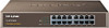
...chapter describes the features of the model of TL-SF1016. 1.1 Product Overview TL-SF1016/TL-SF1016DS/TL-SF1024/TL-SF1024D/TL-SF1048 16/24/48-port Switch provides 16/24/48 10/100Mbps Auto-Negotiation RJ45 ports. TL-SF1016, TL-SF1024 and TL-SF1048 just differ in the size, the ...Plug- Each port of the TL-SF1016 / TL-SF1016DS / TL-SF1024 / TL-SF1024D / TL-SF1048 supports auto MDI/MDI-X function, eliminating the need for monitoring power, link, activity, speed ¾ Rack-mountable steel case ¾ Internal power supply 2 The TL-SF1016/TL-SF1016DS/TL-SF1024/TL-SF1024D/TL-SF1048 16/24/48-port ...
...chapter describes the features of the model of TL-SF1016. 1.1 Product Overview TL-SF1016/TL-SF1016DS/TL-SF1024/TL-SF1024D/TL-SF1048 16/24/48-port Switch provides 16/24/48 10/100Mbps Auto-Negotiation RJ45 ports. TL-SF1016, TL-SF1024 and TL-SF1048 just differ in the size, the ...Plug- Each port of the TL-SF1016 / TL-SF1016DS / TL-SF1024 / TL-SF1024D / TL-SF1048 supports auto MDI/MDI-X function, eliminating the need for monitoring power, link, activity, speed ¾ Rack-mountable steel case ¾ Internal power supply 2 The TL-SF1016/TL-SF1016DS/TL-SF1024/TL-SF1024D/TL-SF1048 16/24/48-port ...

User Guide
Page 10
... weight of the Switch with the provided power cord. Caution: Please avoid any heavy thing placed on the Switch. 3.2.2 Rack Installation To install the Switch in an EIA standard-sized, 19-inch rack, follow the steps: 1) Set the Switch on the bottom at each corner of the Switch. Caution: Please unplug the... removing the Switch. 3.2.1 Desktop Installation To install the Switch on the desktop. 3.2 Installation This Switch can be either installed on the standard 19-inch mountable rack or located on the desktop, please follow the instructions described below: 6
... weight of the Switch with the provided power cord. Caution: Please avoid any heavy thing placed on the Switch. 3.2.2 Rack Installation To install the Switch in an EIA standard-sized, 19-inch rack, follow the steps: 1) Set the Switch on the bottom at each corner of the Switch. Caution: Please unplug the... removing the Switch. 3.2.1 Desktop Installation To install the Switch on the desktop. 3.2 Installation This Switch can be either installed on the standard 19-inch mountable rack or located on the desktop, please follow the instructions described below: 6

User Guide
Page 11
Figure 3-2 Attaching Brackets 2) After the brackets are attached to the Switch, use suitable screws (not provided) to secure the brackets to the Switch with supplied screws, as illustrated in the following figure. Note: TL-SF1016DS and TL-SF1024D do not support rack installation. 7 Figure 3-3 Mounting Switch 3) Connect the Switch to network devices. 4) Supply power to the rack, as illustrated in the following figure. 1) Secure the supplied rack-mounting brackets to each side of the Switch with the provided power cord.
Figure 3-2 Attaching Brackets 2) After the brackets are attached to the Switch, use suitable screws (not provided) to secure the brackets to the Switch with supplied screws, as illustrated in the following figure. Note: TL-SF1016DS and TL-SF1024D do not support rack installation. 7 Figure 3-3 Mounting Switch 3) Connect the Switch to network devices. 4) Supply power to the rack, as illustrated in the following figure. 1) Secure the supplied rack-mounting brackets to each side of the Switch with the provided power cord.