
User Guide
Page 6
.../24/48 10/100Mbps Auto-Negotiation RJ45 ports supporting Auto- Each port of the TL-SF1016 / TL-SF1016DS / TL-SF1024 / TL-SF1024D / TL-SF1048 supports auto MDI/MDI-X function, eliminating the need for monitoring power, link, activity, speed ¾ Rack-mountable steel case ¾ Internal power supply 2 and-Play and any port can be simply plugged into a server, a hub or...
.../24/48 10/100Mbps Auto-Negotiation RJ45 ports supporting Auto- Each port of the TL-SF1016 / TL-SF1016DS / TL-SF1024 / TL-SF1024D / TL-SF1048 supports auto MDI/MDI-X function, eliminating the need for monitoring power, link, activity, speed ¾ Rack-mountable steel case ¾ Internal power supply 2 and-Play and any port can be simply plugged into a server, a hub or...
User Guide
Page 7
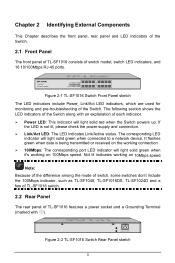
...red when the Switch powers up. Not lit indicates working on 10Mbps speed. Figure 2-2 TL-SF1016 Switch Rear Panel sketch 3 It flashes green when data is not lit, please check the power supply and connection. ¾ Link/Act LED: The LED indicates Link/Active status. If ...such as TL-SF1048, TL-SF1016DS, TL-SF1024D and a few of TL-SF1016 switch. 2.2 Rear Panel The rear panel of TL-SF1016 features a power socket and a Grounding Terminal (marked with an explanation of the Switch along with ). Figure 2-1 TL-SF1016 Switch Front Panel sketch The LED indicators include Power, Link/Act LED ...
...red when the Switch powers up. Not lit indicates working on 10Mbps speed. Figure 2-2 TL-SF1016 Switch Rear Panel sketch 3 It flashes green when data is not lit, please check the power supply and connection. ¾ Link/Act LED: The LED indicates Link/Active status. If ...such as TL-SF1048, TL-SF1016DS, TL-SF1024D and a few of TL-SF1016 switch. 2.2 Rear Panel The rear panel of TL-SF1016 features a power socket and a Grounding Terminal (marked with an explanation of the Switch along with ). Figure 2-1 TL-SF1016 Switch Front Panel sketch The LED indicators include Power, Link/Act LED ...

User Guide
Page 11
Note: TL-SF1016DS and TL-SF1024D do not support rack installation. 7 Figure 3-3 Mounting Switch 3) Connect the Switch to network devices. 4) Supply power to each side of the Switch with the provided power cord. 1) Secure the supplied rack-mounting brackets to the Switch with supplied screws, as illustrated in the following figure. Figure 3-2 Attaching Brackets 2) After the brackets are attached to the Switch, use suitable screws (not provided) to secure the brackets to the rack, as illustrated in the following figure.
Note: TL-SF1016DS and TL-SF1024D do not support rack installation. 7 Figure 3-3 Mounting Switch 3) Connect the Switch to network devices. 4) Supply power to each side of the Switch with the provided power cord. 1) Secure the supplied rack-mounting brackets to the Switch with supplied screws, as illustrated in the following figure. Figure 3-2 Attaching Brackets 2) After the brackets are attached to the Switch, use suitable screws (not provided) to secure the brackets to the rack, as illustrated in the following figure.

User Guide
Page 13
... may differ from the figure above. The power plug you intend to connect the Switch to illustrate the application and principle. Connect the Switch and power outlet by an AC Power Supply. Powering on The TL-SF1016/TL-SF1016DS/TL-SF1024/TL-SF1024D/TL-SF1048 16/24/48-port 10/100Mbps Fast... Ethernet Switch is well grounded in advance. 3.4 Power on the Switch, it will be automatically initialized ...
... may differ from the figure above. The power plug you intend to connect the Switch to illustrate the application and principle. Connect the Switch and power outlet by an AC Power Supply. Powering on The TL-SF1016/TL-SF1016DS/TL-SF1024/TL-SF1024D/TL-SF1048 16/24/48-port 10/100Mbps Fast... Ethernet Switch is well grounded in advance. 3.4 Power on the Switch, it will be automatically initialized ...


