
MC100CM User Guide.
Page 3
COPYRIGHT & TRADEMARKS Specifications are trademarks or registered trademarks of their respective holders. No part of TP-LINK TECHNOLOGIES CO., LTD. is a registered trademark of the specifications may be reproduced in any form or by any derivative such as translation, transformation, or adaptation without notice. http://www.tp-link.com Other brands and product names are subject to make any means or used to change without permission from TP-LINK TECHNOLOGIES CO., LTD. All rights reserved. Copyright © 2011 TP-LINK TECHNOLOGIES CO., LTD.
COPYRIGHT & TRADEMARKS Specifications are trademarks or registered trademarks of their respective holders. No part of TP-LINK TECHNOLOGIES CO., LTD. is a registered trademark of the specifications may be reproduced in any form or by any derivative such as translation, transformation, or adaptation without notice. http://www.tp-link.com Other brands and product names are subject to make any means or used to change without permission from TP-LINK TECHNOLOGIES CO., LTD. All rights reserved. Copyright © 2011 TP-LINK TECHNOLOGIES CO., LTD.

MC100CM User Guide.
Page 4
... receiver is connected. • Consult the dealer or an experienced radio/ TV technician for a Class B digital device, pursuant to part 15 of the FCC Rules. This device complies with the limits for help. However, there is subject to radio or television reception, which can radiate radio frequency energy and, if not installed and used in accordance with the instructions, may cause undesired operation...
... receiver is connected. • Consult the dealer or an experienced radio/ TV technician for a Class B digital device, pursuant to part 15 of the FCC Rules. This device complies with the limits for help. However, there is subject to radio or television reception, which can radiate radio frequency energy and, if not installed and used in accordance with the instructions, may cause undesired operation...

MC100CM User Guide.
Page 5
In a domestic environment, this product may cause radio interference, in which case the user may be required to operate the equipment. Any changes or modifications not expressly approved by the party responsible for compliance could void the user's authority to take adequate measures. CE Mark Warning This is a class B product.
In a domestic environment, this product may cause radio interference, in which case the user may be required to operate the equipment. Any changes or modifications not expressly approved by the party responsible for compliance could void the user's authority to take adequate measures. CE Mark Warning This is a class B product.

MC100CM User Guide.
Page 6
CONTENTS Package contents 1 Chapter 1 Introduction 2 1.1 Overview of the Converter 2 1.2 Conventions 3 1.3 Features 3 1.4 Connectors and Network Cables Supported 3 1.5 Appearance Indication 4 1.5.1 LED Indicators 4 1.5.2 Switch 6 1.5.3 Link Fault Pass Through Function 7 Chapter 2 Installation Guide 9 2.1 Fast Ethernet Media Converter 9 2.2 WDM Fast Ethernet Media Converter 9 Chapter 3 Configuration 11 3.1 Installation Procedure 12 Appendix: Specifications 13
CONTENTS Package contents 1 Chapter 1 Introduction 2 1.1 Overview of the Converter 2 1.2 Conventions 3 1.3 Features 3 1.4 Connectors and Network Cables Supported 3 1.5 Appearance Indication 4 1.5.1 LED Indicators 4 1.5.2 Switch 6 1.5.3 Link Fault Pass Through Function 7 Chapter 2 Installation Guide 9 2.1 Fast Ethernet Media Converter 9 2.2 WDM Fast Ethernet Media Converter 9 Chapter 3 Configuration 11 3.1 Installation Procedure 12 Appendix: Specifications 13

MC100CM User Guide.
Page 7
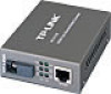
Package contents The following items should be found in your package: ¾ One Converter ¾ One AC-DC Power Adapter (DC9V/600mA) ¾ One User Guide Note: Make sure that the package contains the above items. If any of the listed items are damaged or missing, please contact your distributor. 1
Package contents The following items should be found in your package: ¾ One Converter ¾ One AC-DC Power Adapter (DC9V/600mA) ¾ One User Guide Note: Make sure that the package contains the above items. If any of the listed items are damaged or missing, please contact your distributor. 1

MC100CM User Guide.
Page 8
Chapter 1 Introduction Thank you use MC111CS and MC112CS instead of fiber via multiplex transmit and receive signals at different wavelengths on single strand cable. Note: This media converter can save half cabling cost when you for choosing the MC100CM/MC110CS Fast Ethernet Media Converters or the MC111CS/MC112CS WDM Fast Ethernet Media Converters! 1.1 Overview of the Converter MC100CM and MC110CS are...
Chapter 1 Introduction Thank you use MC111CS and MC112CS instead of fiber via multiplex transmit and receive signals at different wavelengths on single strand cable. Note: This media converter can save half cabling cost when you for choosing the MC100CM/MC110CS Fast Ethernet Media Converters or the MC111CS/MC112CS WDM Fast Ethernet Media Converters! 1.1 Overview of the Converter MC100CM and MC110CS are...

MC100CM User Guide.
Page 9
... connector. ¾ Supports auto negotiation of duplex mode on TP port. ¾ Supports auto negotiation of 10/100Mbps and auto MID/MID-X for TP port. ¾ Supports Link Fault Pass Through function and Far End Fault function. ¾ Extends fiber distance up to monitor network activity easily. ¾ External power supply. 1.4 Connectors and Network Cables Supported The connectors and network cables supported by the converter are sharing this guide stands for single-mode fiber. ¾ Easy-to-view...
... connector. ¾ Supports auto negotiation of duplex mode on TP port. ¾ Supports auto negotiation of 10/100Mbps and auto MID/MID-X for TP port. ¾ Supports Link Fault Pass Through function and Far End Fault function. ¾ Extends fiber distance up to monitor network activity easily. ¾ External power supply. 1.4 Connectors and Network Cables Supported The connectors and network cables supported by the converter are sharing this guide stands for single-mode fiber. ¾ Easy-to-view...

MC100CM User Guide.
Page 10
... MC112CS-20 RJ45--SC 20km Single-mode Fiber, TP 1310nmTX 1550nmRX MC112CS-40 RJ45--SC 40km Single-mode Fiber, TP 1310nmTX 1550nmRX MC112CS-60 RJ45--SC 60km Single-mode Fiber, TP 1310nmTX 1550nmRX 1.5 Appearance Indication 1.5.1 LED Indicators The converter has LED indicators which can provide a real-time report. Model NO. ¾ Connectors: RJ-45, SC. ¾ Network Cables: Cat.5 Twisted-Pair (below . 4
... MC112CS-20 RJ45--SC 20km Single-mode Fiber, TP 1310nmTX 1550nmRX MC112CS-40 RJ45--SC 40km Single-mode Fiber, TP 1310nmTX 1550nmRX MC112CS-60 RJ45--SC 60km Single-mode Fiber, TP 1310nmTX 1550nmRX 1.5 Appearance Indication 1.5.1 LED Indicators The converter has LED indicators which can provide a real-time report. Model NO. ¾ Connectors: RJ-45, SC. ¾ Network Cables: Cat.5 Twisted-Pair (below . 4

MC100CM User Guide.
Page 11
... connection on Power off The Link Fault Pass Through function enable. On There's a valid link. TP Off The TP port is receiving or transmitting data from the TP port. Off There's no valid link. On The TP port is connected to 100Base-Tx Off The TP port is operating in Half-Duplex mode. FX Link/Act Flashing The converter is operating in Full-Duplex FDX/Col Flashing There's a collision. On The TP port is connected to...
... connection on Power off The Link Fault Pass Through function enable. On There's a valid link. TP Off The TP port is receiving or transmitting data from the TP port. Off There's no valid link. On The TP port is connected to 100Base-Tx Off The TP port is operating in Half-Duplex mode. FX Link/Act Flashing The converter is operating in Full-Duplex FDX/Col Flashing There's a collision. On The TP port is connected to...

MC100CM User Guide.
Page 12
... as shown below, otherwise the Media Converter may not work normally. 6 1.5.2 Switch ¾ TP_AUTO: The TP port operates in Auto-Negotiation mode; ¾ TP_DIS: The TP port operates in FORCE mode; ¾ TP_100M: The TP port operates in 100Base-Tx; ¾ TP_10M: The TP port operates in 10Base-T mode; ¾ TP_FDX: The TP port operates in Full-Duplex mode; ¾ TP_HDX: The TP port operates in Half-Duplex mode; ¾ LFP_OFF: The Link Fault Pass Through function disable...
... as shown below, otherwise the Media Converter may not work normally. 6 1.5.2 Switch ¾ TP_AUTO: The TP port operates in Auto-Negotiation mode; ¾ TP_DIS: The TP port operates in FORCE mode; ¾ TP_100M: The TP port operates in 100Base-Tx; ¾ TP_10M: The TP port operates in 10Base-T mode; ¾ TP_FDX: The TP port operates in Full-Duplex mode; ¾ TP_HDX: The TP port operates in Half-Duplex mode; ¾ LFP_OFF: The Link Fault Pass Through function disable...

MC100CM User Guide.
Page 13
... situations. 2) You have to reset the converter after configuring the switches. 1.5.3 Link Fault Pass Through Function In common situations, when one side of the link fails, the other side continues transmitting packets, and waiting for a response that never arrives from the disconnected side. 7 The Mode Of The Device TP:AUTO; LFP OFF TP:FORCE,100M,FULL; LFP ON...
... situations. 2) You have to reset the converter after configuring the switches. 1.5.3 Link Fault Pass Through Function In common situations, when one side of the link fails, the other side continues transmitting packets, and waiting for a response that never arrives from the disconnected side. 7 The Mode Of The Device TP:AUTO; LFP OFF TP:FORCE,100M,FULL; LFP ON...

MC100CM User Guide.
Page 14
...port (B) then forces its TP port (B) to notice the FX port (B). With the Link Fault Pass Through function enabled (optional with switch LFP), TP port and FX port of the same converter will inform each other the fault link status so that when one side of the link fails, the other side will force the link...will also be illustrated as noticed. Link status LED will be off for both Converters and Devices as shown below . If link fail happens on TP port (A), the FX port (A) sends non-idle pattern to link failed after receiving the non-idle pattern. Link LED Device A Off Device B Off...
...port (B) then forces its TP port (B) to notice the FX port (B). With the Link Fault Pass Through function enabled (optional with switch LFP), TP port and FX port of the same converter will inform each other the fault link status so that when one side of the link fails, the other side will force the link...will also be illustrated as noticed. Link status LED will be off for both Converters and Devices as shown below . If link fail happens on TP port (A), the FX port (A) sends non-idle pattern to link failed after receiving the non-idle pattern. Link LED Device A Off Device B Off...

MC100CM User Guide.
Page 15
... fiber connector of MC111CS transmits data by 1550nm short wave laser while receives data by 1550nm short wave laser on single-mode fiber. The SC fiber connector of MC110CS transmits/receives data by 1310nm short wave laser on different fibers Note: You have to use either two MC100CM connectors or two MC110CS connectors to cooperate. 2.2 WDM Fast Ethernet Media Converter 1. Chapter 2 Installation Guide 2.1 Fast Ethernet Media...
... fiber connector of MC111CS transmits data by 1550nm short wave laser while receives data by 1550nm short wave laser on single-mode fiber. The SC fiber connector of MC110CS transmits/receives data by 1310nm short wave laser on different fibers Note: You have to use either two MC100CM connectors or two MC110CS connectors to cooperate. 2.2 WDM Fast Ethernet Media Converter 1. Chapter 2 Installation Guide 2.1 Fast Ethernet Media...

MC100CM User Guide.
Page 16
Transmits and receives data on the same fiber Note: You have to use MC111CS and MC112CS at the same time to cooperate. 10
Transmits and receives data on the same fiber Note: You have to use MC111CS and MC112CS at the same time to cooperate. 10

MC100CM User Guide.
Page 17
Error will occur when you can use the converter like the following end devices. Another effective application is to place one MC112CS to expand your network. Place two converters back to back between a 10/100Base-TX network and a 100Base-FX device. 11 Note: You should use other ways. 2. Chapter 3 Configuration In order to achieve the aim of effectively expanding a Fast Ethernet network, you use two MC100CM Media Converters or two MC110CS Media Converters, or one MC111CS and one converter directly between the following examples: 1.
Error will occur when you can use the converter like the following end devices. Another effective application is to place one MC112CS to expand your network. Place two converters back to back between a 10/100Base-TX network and a 100Base-FX device. 11 Note: You should use other ways. 2. Chapter 3 Configuration In order to achieve the aim of effectively expanding a Fast Ethernet network, you use two MC100CM Media Converters or two MC110CS Media Converters, or one MC111CS and one converter directly between the following examples: 1.

MC100CM User Guide.
Page 18
...; Use a SC fiber cable to connect the two Converters' SC connector or the SC connecter of the cable to the RJ45 jack on the power. 12 Connection of a Converter and a 10/100Base-TX Device (HUB or Switch). • Make sure that the length of the Cat.5 twisted pair cable between the 10/100Base-TX device and the converter is less than 100 meters...
...; Use a SC fiber cable to connect the two Converters' SC connector or the SC connecter of the cable to the RJ45 jack on the power. 12 Connection of a Converter and a 10/100Base-TX Device (HUB or Switch). • Make sure that the length of the Cat.5 twisted pair cable between the 10/100Base-TX device and the converter is less than 100 meters...
MC100CM User Guide.
Page 19
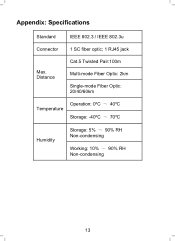
Distance Cat.5 Twisted Pair:100m Multi-mode Fiber Optic: 2km Single-mode Fiber Optic: 20/40/60km Temperature Operation: 0ºC ~ 40ºC Storage: -40ºC ~ 70ºC Humidity Storage: 5% ~ 90% RH Non-condensing Working: 10% ~ 90% RH Non-condensing 13 Appendix: Specifications Standard IEEE 802.3 / IEEE 802.3u Connector 1 SC fiber optic; 1 RJ45 jack Max.
Distance Cat.5 Twisted Pair:100m Multi-mode Fiber Optic: 2km Single-mode Fiber Optic: 20/40/60km Temperature Operation: 0ºC ~ 40ºC Storage: -40ºC ~ 70ºC Humidity Storage: 5% ~ 90% RH Non-condensing Working: 10% ~ 90% RH Non-condensing 13 Appendix: Specifications Standard IEEE 802.3 / IEEE 802.3u Connector 1 SC fiber optic; 1 RJ45 jack Max.


