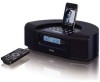
Service Manual
Page 1
... and capacitors, refer to the appropriate parts list and ensure exact replacement. they must be used only with this manual. ! The parts with identical components - SR-L250i HI-FI TABLE RADIO/CD NOTES CONTENTS PC board shown are not supplied. refer to the circuit diagrams contained in the exploded views are viewed...
Service Manual
Page 2
SR-L250i 1 SAFETY INFORMATION Optical pickup : Type : DA23SR Manufacturer : SANYO Electric Co.,Ltd. Laser output : Less than 0.5mW on the objective lens Wavelength : 760-800nm
Service Manual
Page 3
... (CR2032) x1 AM loop antenna x 1 Dock adapter x 6 (adapter "60GB(color) + photo 40/60GB" premounted) Stereo mini plug cable x 1 AC Adapter x 1 Owner's Manual x 1 Warranty Card x 1 (EUR) SR-L250i Design and specifications are approximate.
Service Manual
Page 4
... loop antenna across the output of the signal generator. 4. Set the BAND switch to the PHONES JACK terminal. 5. Connect the oscilloscope to the FM position. 3. SR-L250i 3 ADJUSTMENTS AND CHECKS 3-1 TUNER SECTION Use a screwdriver with a plastic or ceramic grip for all adjustment. 3-1-1 AM adjustment 1. Connect the oscilloscope to "ANT" on TUNER PCB...
Service Manual
Page 9
SR-L250i EXPLODED VIEW-1 PARTS LIST REF.NO TEAC PARTS NO. PARTS NO. 1-1 1-2 1-3 010-250B0900-R 010-230W0300-R 010-250B1000-R 010-230W0400-R 023-23010033-R DESCRIPTION DUCT COVER (COLOR:BLACK) DUCT COVER (COLOR:WHITE) DUCT COVER (...
Service Manual
Page 13
SR-L250i EXPLODED VIEW-3 PARTS LIST REF.NO TEAC PARTS NO. PARTS NO. 3-1 3-2 3-3 023-23010033-R 3-4 023-23010032-R 3-5 DESCRIPTION SPEAKER BOX L ASSY SPEAKER BOX R ASSY SCREW 3X10MM BB BLACK HD SCREW 3X10MM BB ZMC HD ...
Service Manual
Page 17
SR-L250i EXPLODED VIEW-5 PARTS LIST REF.NO TEAC PARTS NO. PARTS NO. 5-1 5-2 5-3 020-250B0100-R 020-250S0100-R 051-R230i001-R 001-250B0200-R 001-250W0200-R DESCRIPTION SPEAKER METAL NET (COLOR:BLACK) SPEAKER METAL NET (COLOR:SILVER) ...