

Instruction Manual
Page 4
... to be taken as shown in the illustration above the text - The screws must not be taken that is clamped in the "STIHL Special Tools" manual. Introduction and Safety Precautions 2710RA320 TG 1.1 Introduction This service manual contains detailed descriptions of movement @ 4.2 =Reference ... Use the part numbers to check the part numbers of the individual components and assemblies. To do this example. 1 3 2 Servicing and repairs are included in this , secure the mounting plate (2) 5910 850 1650 to assembly stand (3) 5910 890 3101. MS 231, MS 231 C, MS 251, MS 251 C 3 To...
... to be taken as shown in the illustration above the text - The screws must not be taken that is clamped in the "STIHL Special Tools" manual. Introduction and Safety Precautions 2710RA320 TG 1.1 Introduction This service manual contains detailed descriptions of movement @ 4.2 =Reference ... Use the part numbers to check the part numbers of the individual components and assemblies. To do this example. 1 3 2 Servicing and repairs are included in this , secure the mounting plate (2) 5910 850 1650 to assembly stand (3) 5910 890 3101. MS 231, MS 231 C, MS 251, MS 251 C 3 To...
Instruction Manual
Page 5
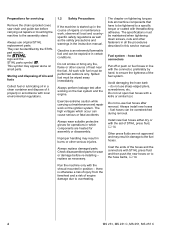
...must be overstretched during removal. The high voltages which components are not approved and may result in damage to overheating. 4 MS 231, MS 231 C, MS 251, MS 251 C Always wear suitable protective gloves for operations in accordance with threadlocking adhesive. Avoid damaging the hose barb - Run the ...or maintenance work with the aid of the hoses and the connectors with the connector, preferably by the STIHL part number, the { logo and the STIHL parts symbol K This symbol may result in all local and countryspecific safety regulations as well as necessary. fuel...
...must be overstretched during removal. The high voltages which components are not approved and may result in damage to overheating. 4 MS 231, MS 231 C, MS 251, MS 251 C Always wear suitable protective gloves for operations in accordance with threadlocking adhesive. Avoid damaging the hose barb - Run the ...or maintenance work with the aid of the hoses and the connectors with the connector, preferably by the STIHL part number, the { logo and the STIHL parts symbol K This symbol may result in all local and countryspecific safety regulations as well as necessary. fuel...
Instruction Manual
Page 19
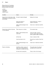
... filter Fit new hose or position it free from kinks Clean bore or install new manifold. 3.7 Engine Always check and, if necessary, repair the following parts before looking for faults on fan housing 18 MS 231, MS 231 C, MS 251, MS 251 C
... filter Fit new hose or position it free from kinks Clean bore or install new manifold. 3.7 Engine Always check and, if necessary, repair the following parts before looking for faults on fan housing 18 MS 231, MS 231 C, MS 251, MS 251 C
Instruction Manual
Page 20
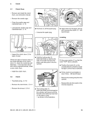
... stub, b 14 - If it is less than about 80% of wear. as shown in the reverse sequence. 2310RA005 TG 2310RA003 TG - MS 231, MS 231 C, MS 251, MS 251 C 19 Remove the clutch drum, b 4.1 2310RA002 TG 1 2 Fit the cover washer (1) so that the word "TOP" faces outwards. ...on the inside diameter of its metal top faces the piston and then push it down firmly - Clutch 4.1 Clutch Drum - Reassemble all other parts in the illustration. 4. Remove and install the clutch drum, see instruction manual. - lefthand thread. 2310RA004 TG 1 1 Installing TOP 5902RA018 TG...
... stub, b 14 - If it is less than about 80% of wear. as shown in the reverse sequence. 2310RA005 TG 2310RA003 TG - MS 231, MS 231 C, MS 251, MS 251 C 19 Remove the clutch drum, b 4.1 2310RA002 TG 1 2 Fit the cover washer (1) so that the word "TOP" faces outwards. ...on the inside diameter of its metal top faces the piston and then push it down firmly - Clutch 4.1 Clutch Drum - Reassemble all other parts in the illustration. 4. Remove and install the clutch drum, see instruction manual. - lefthand thread. 2310RA004 TG 1 1 Installing TOP 5902RA018 TG...
Instruction Manual
Page 21
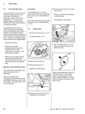
...) - Troubleshooting, b 3.2 - With the chain brake activated (locked), open the throttle wide and let go of the most important safety devices on inside diameter and/or parts of its remaining thickness is measured in order if deceleration of the chain braking time, i.e. the time that elapses between activating the brake and the..., fine particles of abrasion, etc.) and smoothing of the friction surfaces of the brake band and clutch drum impair the coefficient of the machine. 20 MS 231, MS 231 C, MS 251, MS 251 C
...) - Troubleshooting, b 3.2 - With the chain brake activated (locked), open the throttle wide and let go of the most important safety devices on inside diameter and/or parts of its remaining thickness is measured in order if deceleration of the chain braking time, i.e. the time that elapses between activating the brake and the..., fine particles of abrasion, etc.) and smoothing of the friction surfaces of the brake band and clutch drum impair the coefficient of the machine. 20 MS 231, MS 231 C, MS 251, MS 251 C
Instruction Manual
Page 22
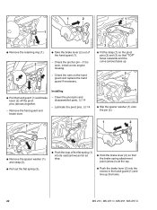
... the chain brake : Hold the brake band (1) sideways, attach it to disconnect the brake spring (1) from the brake lever. 2310RA015 TG MS 231, MS 231 C, MS 251, MS 251 C 21 Carry out the other parts in the reverse sequence. : Fit the screw (2) on the underside of the machine and tighten it in the direction of its seat...
... the chain brake : Hold the brake band (1) sideways, attach it to disconnect the brake spring (1) from the brake lever. 2310RA015 TG MS 231, MS 231 C, MS 251, MS 251 C 21 Carry out the other parts in the reverse sequence. : Fit the screw (2) on the underside of the machine and tighten it in the direction of its seat...
Instruction Manual
Page 23
...) as far as stop. : Hold the brake lever (2) so that "TOP" faces outwards and the curve (arrow) faces up the holes. 2310RA023 TG 22 MS 231, MS 231 C, MS 251, MS 251 C Remove the hand guard and brake lever. - Check the anchor pin - Lubricate the pivot pins, b 14 1 2 1 : Slip the spacer washer (1) ...strap (2). : Pull out the flat spring (3). 2310RA018 TG 2310RA020 TG TOP : Push the loop of the hand guard (1). - Clean the pivot pins and disassembled parts, b 14 - if it is at the top. : Push the brake lever (2) into the recess in the hand guard (1) and line up . 2 2310RA017...
...) as far as stop. : Hold the brake lever (2) so that "TOP" faces outwards and the curve (arrow) faces up the holes. 2310RA023 TG 22 MS 231, MS 231 C, MS 251, MS 251 C Remove the hand guard and brake lever. - Check the anchor pin - Lubricate the pivot pins, b 14 1 2 1 : Slip the spacer washer (1) ...strap (2). : Pull out the flat spring (3). 2310RA018 TG 2310RA020 TG TOP : Push the loop of the hand guard (1). - Clean the pivot pins and disassembled parts, b 14 - if it is at the top. : Push the brake lever (2) into the recess in the hand guard (1) and line up . 2 2310RA017...
Instruction Manual
Page 24
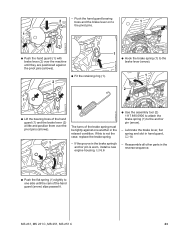
...). - Lubricate the brake lever, flat spring and slot in the brake spring's anchor pin is not the case, replace the brake spring. - MS 231, MS 231 C, MS 251, MS 251 C 23 Reassemble all other parts in the reverse sequence. 2310RA026 TG : Push the flat spring (1) slightly to one another in the relaxed condition. - Push the hand guard...
...). - Lubricate the brake lever, flat spring and slot in the brake spring's anchor pin is not the case, replace the brake spring. - MS 231, MS 231 C, MS 251, MS 251 C 23 Reassemble all other parts in the reverse sequence. 2310RA026 TG : Push the flat spring (1) slightly to one another in the relaxed condition. - Push the hand guard...
Instruction Manual
Page 25
... housing. - Clean the pivot pins and disassembled parts, b 14 - Engage the chain brake. Remove the hand guard and brake lever. 2310RA033 TG 1 : Take the brake lever (2) out of the flat spring (1) into its seat (arrow) as far as stop. 2310RA020 TG 24 MS 231, MS 231 C, MS 251, MS 251 C Troubleshooting, b 3.2 - Check the anchor pin - if it...
... housing. - Clean the pivot pins and disassembled parts, b 14 - Engage the chain brake. Remove the hand guard and brake lever. 2310RA033 TG 1 : Take the brake lever (2) out of the flat spring (1) into its seat (arrow) as far as stop. 2310RA020 TG 24 MS 231, MS 231 C, MS 251, MS 251 C Troubleshooting, b 3.2 - Check the anchor pin - if it...

Instruction Manual
Page 27
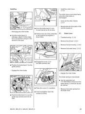
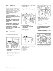
...to guarantee correct operation of free travel is not the case, replace the brake spring. - Adjust the brake cable, b 5.4.1 - Reassemble all other parts in the relaxed condition. Free travel - Lubricate the brake lever, flat spring and slot in order, the reason may be within the mark (a). ...TOP : Attach the spring (1) to the brake lever (arrow) so that position. Free travel is necessary to the brake lever (arrow). 26 MS 231, MS 231 C, MS 251, MS 251 C If the groove in the brake spring's anchor pin is worn, install a new engine housing, b 6.6 1 If problems occur on ...
...to guarantee correct operation of free travel is not the case, replace the brake spring. - Adjust the brake cable, b 5.4.1 - Reassemble all other parts in the relaxed condition. Free travel - Lubricate the brake lever, flat spring and slot in order, the reason may be within the mark (a). ...TOP : Attach the spring (1) to the brake lever (arrow) so that position. Free travel is necessary to the brake lever (arrow). 26 MS 231, MS 231 C, MS 251, MS 251 C If the groove in the brake spring's anchor pin is worn, install a new engine housing, b 6.6 1 If problems occur on ...
Instruction Manual
Page 28
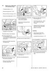
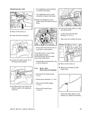
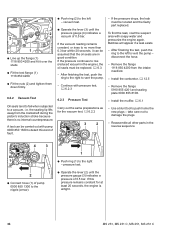
... brake cable - Turn adjusting screw counter- Loosen and lower the tank TOP housing, b 12.11.2 1 - Reassemble all other parts in that position. Check the brake cable (1) and retainer (2), replace if necessary MS 231, MS 231 C, MS 251, MS 251 C 27 Remove the throttle trigger, b 10.3 2310RA053 TG - Turn adjusting screw clockwise to stretch the hose. 2310RA044 TG...
... brake cable - Turn adjusting screw counter- Loosen and lower the tank TOP housing, b 12.11.2 1 - Reassemble all other parts in that position. Check the brake cable (1) and retainer (2), replace if necessary MS 231, MS 231 C, MS 251, MS 251 C 27 Remove the throttle trigger, b 10.3 2310RA053 TG - Turn adjusting screw clockwise to stretch the hose. 2310RA044 TG...
Instruction Manual
Page 30
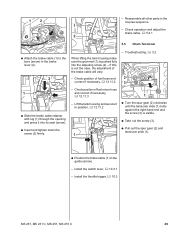
Install the throttle trigger, b 10.3 MS 231, MS 231 C, MS 251, MS 251 C 29 Reassemble all other parts in the guide (arrow). - Check position of fuel return hose and correct if necessary, b 12.11.3 - Lift the tank housing and secure it into the ...
Install the throttle trigger, b 10.3 MS 231, MS 231 C, MS 251, MS 251 C 29 Reassemble all other parts in the guide (arrow). - Check position of fuel return hose and correct if necessary, b 12.11.3 - Lift the tank housing and secure it into the ...
Instruction Manual
Page 31
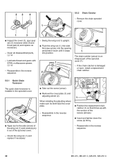
22 4 1 5.5.2 Chain Catcher - Clean all disassembled parts, b 14 - Reassemble in the reverse sequence. - Check the wing nut (1) and replace if necessary 30 MS 231, MS 231 C, MS 251, MS 251 C Remove the chain sprocket cover. 165RA007 TG 533RA058 TG 2310RA048 TG 1 3 : Inspect the cover (1), ...The chain catcher (arrow) is installed in the reverse sequence. 1 : Position the replacement chain catcher (1) so that it lines up with STIHL multipurpose grease, b 14 - Reassemble in the reverse sequence. - If the chain catcher is damaged or worn, install a replacement chain catcher...
22 4 1 5.5.2 Chain Catcher - Clean all disassembled parts, b 14 - Reassemble in the reverse sequence. - Check the wing nut (1) and replace if necessary 30 MS 231, MS 231 C, MS 251, MS 251 C Remove the chain sprocket cover. 165RA007 TG 533RA058 TG 2310RA048 TG 1 3 : Inspect the cover (1), ...The chain catcher (arrow) is installed in the reverse sequence. 1 : Position the replacement chain catcher (1) so that it lines up with STIHL multipurpose grease, b 14 - Reassemble in the reverse sequence. - If the chain catcher is damaged or worn, install a replacement chain catcher...
Instruction Manual
Page 32
Coat the collar stud with threadlocking adhesive, b 14 - MS 231, MS 231 C, MS 251, MS 251 C 31 the security of the collar stud (1) with threadlocking adhesive, fit and tighten down firmly. - Reassemble all other parts in the engine housing is no longer guaranteed. 5.6 Bar Mounting Stud - Remove the chain ...is badly damaged or stripped it will not be possible to tighten the standard collar stud to the specified torque - Reassemble all other parts in the screw list as a repair solution, b 2.5. 1 2310RA046 TG 2310RA047 TG : Push stud puller 5910 893 0501 (1) ...
Coat the collar stud with threadlocking adhesive, b 14 - MS 231, MS 231 C, MS 251, MS 251 C 31 the security of the collar stud (1) with threadlocking adhesive, fit and tighten down firmly. - Reassemble all other parts in the engine housing is no longer guaranteed. 5.6 Bar Mounting Stud - Remove the chain ...is badly damaged or stripped it will not be possible to tighten the standard collar stud to the specified torque - Reassemble all other parts in the screw list as a repair solution, b 2.5. 1 2310RA046 TG 2310RA047 TG : Push stud puller 5910 893 0501 (1) ...
Instruction Manual
Page 34
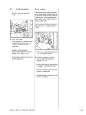
....25 mm c = 6 mm - do not tighten down firmly. - This can be modified as shown. Moreover, the transition from idle speed to part or full throttle is in castings are the usual causes of the prescribed idle speed difficult, if not impossible. Such faults allow supplementary air to....5 - 2310RA072 TG 2310RA074 TG 6.2 Leakage Test Defective oil seals and gaskets or cracks in place. 2310RA079 TG a 2710RA164 TG 2310RA073 TG MS 231, MS 231 C, MS 251, MS 251 C 33 This makes adjustment of leaks. The engine can be checked through the spark plug hole. : Make sure the washer (1) is ...
....25 mm c = 6 mm - do not tighten down firmly. - This can be modified as shown. Moreover, the transition from idle speed to part or full throttle is in castings are the usual causes of the prescribed idle speed difficult, if not impossible. Such faults allow supplementary air to....5 - 2310RA072 TG 2310RA074 TG 6.2 Leakage Test Defective oil seals and gaskets or cracks in place. 2310RA079 TG a 2710RA164 TG 2310RA073 TG MS 231, MS 231 C, MS 251, MS 251 C 33 This makes adjustment of leaks. The engine can be checked through the spark plug hole. : Make sure the washer (1) is ...
Instruction Manual
Page 35
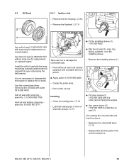
...lifts away from the intake manifold. - If the pressure drops, the leak must be located and the faulty part replaced. Reassemble all other parts in good condition. If the vacuum reading remains constant, or rises to no internal counterpressure. To find the ...must be replaced, b 6.3. - Remove the flange 1118 850 4200 from the crankshaft during the piston's induction stroke because there is airtight. 34 MS 231, MS 231 C, MS 251, MS 251 C pressure test. : Operate the lever (2) until the pressure gauge (4) indicates a vacuum of 0.5 bar. Bubbles will appear if a leak ...
...lifts away from the intake manifold. - If the pressure drops, the leak must be located and the faulty part replaced. Reassemble all other parts in good condition. If the vacuum reading remains constant, or rises to no internal counterpressure. To find the ...must be replaced, b 6.3. - Remove the flange 1118 850 4200 from the crankshaft during the piston's induction stroke because there is airtight. 34 MS 231, MS 231 C, MS 251, MS 251 C pressure test. : Operate the lever (2) until the pressure gauge (4) indicates a vacuum of 0.5 bar. Bubbles will appear if a leak ...
Instruction Manual
Page 36
... snap ring - Installing - Clean the sealing face, b 14 - Degrease the crankshaft taper, b 14 - Clamp the puller arms. - Reassemble all other parts in its open side facing the ball bearing. MS 231, MS 231 C, MS 251, MS 251 C 35 Use the correct jaws when removing the oil seals with a suitable tube or a punch. : Apply puller (1) 5910 890 4400...
... snap ring - Installing - Clean the sealing face, b 14 - Degrease the crankshaft taper, b 14 - Clamp the puller arms. - Reassemble all other parts in its open side facing the ball bearing. MS 231, MS 231 C, MS 251, MS 251 C 35 Use the correct jaws when removing the oil seals with a suitable tube or a punch. : Apply puller (1) 5910 890 4400...
Instruction Manual
Page 37
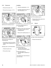
Lubricate sealing lips of new oil seal with a suitable tube or a punch. - Reassemble all other parts in its seat by 1 tapping it with grease, b 14 1 2310RA087 TG 1 : Fit the retaining ring (1). 1 - Remove the installing sleeve (1). 1 2 : Take out the screws (arrows). Remove ... sleeve (1) 1122 893 2405 to damage the crankshaft stub. - Clean the sealing face, b 14 - The seating face must be flat and free from burrs. 36 MS 231, MS 231 C, MS 251, MS 251 C 6.3.2 Clutch side Installing - Remove the clutch, b 4 - Clamp the puller arms. -
Lubricate sealing lips of new oil seal with a suitable tube or a punch. - Reassemble all other parts in its seat by 1 tapping it with grease, b 14 1 2310RA087 TG 1 : Fit the retaining ring (1). 1 - Remove the installing sleeve (1). 1 2 : Take out the screws (arrows). Remove ... sleeve (1) 1122 893 2405 to damage the crankshaft stub. - Clean the sealing face, b 14 - The seating face must be flat and free from burrs. 36 MS 231, MS 231 C, MS 251, MS 251 C 6.3.2 Clutch side Installing - Remove the clutch, b 4 - Clamp the puller arms. -
Instruction Manual
Page 38
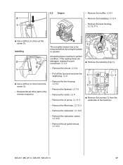
2310RA083 TG 6.5 Engine - All sealing faces must be removed before removing the piston or cylinder. Reassemble all other parts in perfect condition. Remove the air guide shroud, b 12.4 2310RA092 TG MS 231, MS 231 C, MS 251, MS 251 C 37 Remove the flywheel, b 7.6 - Remove the oil pump, b 11.3 - Installing 2 1 1 The complete engine has to drive out the screw (1). If...
2310RA083 TG 6.5 Engine - All sealing faces must be removed before removing the piston or cylinder. Reassemble all other parts in perfect condition. Remove the air guide shroud, b 12.4 2310RA092 TG MS 231, MS 231 C, MS 251, MS 251 C 37 Remove the flywheel, b 7.6 - Remove the oil pump, b 11.3 - Installing 2 1 1 The complete engine has to drive out the screw (1). If...
Instruction Manual
Page 39
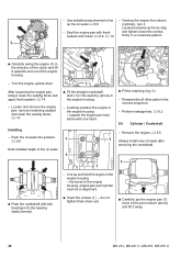
... engine upside down yet. : Carefully pry the engine pan (1) loose at the point shown (arrow) and lift it away. 38 MS 231, MS 231 C, MS 251, MS 251 C Remove the engine, b 6.5 Always install new oil seals after removing the crankshaft. 1 2310RA427 TG 2310RA092 TG 2310RA098 TG - ... 6.6 Cylinder / Crankshaft - the bores in the engine housing, engine pan and cylinder must be in the reverse sequence. - Reassemble all other parts in alignment. : Push the crankshaft with ball bearings into position, b 6.6 Note installed depth of the engine housing. - After loosening the engine ...
... engine upside down yet. : Carefully pry the engine pan (1) loose at the point shown (arrow) and lift it away. 38 MS 231, MS 231 C, MS 251, MS 251 C Remove the engine, b 6.5 Always install new oil seals after removing the crankshaft. 1 2310RA427 TG 2310RA092 TG 2310RA098 TG - ... 6.6 Cylinder / Crankshaft - the bores in the engine housing, engine pan and cylinder must be in the reverse sequence. - Reassemble all other parts in alignment. : Push the crankshaft with ball bearings into position, b 6.6 Note installed depth of the engine housing. - After loosening the engine ...


