

Instruction Manual
Page 2
... 5.4.2 Brake cable Removing and Installing 27 5.5 Chain Tensioner 29 5.5.1 Quick Chain Tensioner 30 5.5.2 Chain Catcher 30 5.6 Bar Mounting Stud 31 6. Clutch 19 4.1 Clutch Drum 19 4.2 Clutch 19 5. Servicing the AV System 66 9.1 9.2 9.3 9.3.1 9.3.2 9.4 AV Spring on Oil Tank 66 AV Spring on Fuel Tank 66 AV Spring on Handlebar 67 Stop Buffers 68 Buffers on Machines with Manual Fuel Pump 85 12.5 Carburetor 88 12.5.1 Leakage Test 89 RA_737_00_01_01 MS 231, MS 231 C, MS 251, MS 251 C q © ANDREAS STIHL AG & Co. Engine...
... 5.4.2 Brake cable Removing and Installing 27 5.5 Chain Tensioner 29 5.5.1 Quick Chain Tensioner 30 5.5.2 Chain Catcher 30 5.6 Bar Mounting Stud 31 6. Clutch 19 4.1 Clutch Drum 19 4.2 Clutch 19 5. Servicing the AV System 66 9.1 9.2 9.3 9.3.1 9.3.2 9.4 AV Spring on Oil Tank 66 AV Spring on Fuel Tank 66 AV Spring on Handlebar 67 Stop Buffers 68 Buffers on Machines with Manual Fuel Pump 85 12.5 Carburetor 88 12.5.1 Leakage Test 89 RA_737_00_01_01 MS 231, MS 231 C, MS 251, MS 251 C q © ANDREAS STIHL AG & Co. Engine...

Instruction Manual
Page 4
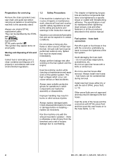
... "STIHL Special Tools" manual. They must not project since publication of this , secure the mounting plate (2) 5910 850 1650 to check the part numbers of the individual components and assemblies. The meanings are listed in the chapter on "Special Servicing Tools" in this manual. The special tools mentioned in the descriptions are as shown in position. MS 231, MS 231 C, MS 251, MS 251 C 3 They show the installed positions of any replacement parts...
... "STIHL Special Tools" manual. They must not project since publication of this , secure the mounting plate (2) 5910 850 1650 to check the part numbers of the individual components and assemblies. The meanings are listed in the chapter on "Special Servicing Tools" in this manual. The special tools mentioned in the descriptions are as shown in position. MS 231, MS 231 C, MS 251, MS 251 C 3 They show the installed positions of any replacement parts...
Instruction Manual
Page 5
... not smoke or bring any fire, flame or other source of STIHL press fluid, b 14. Check disassembled parts for servicing Remove the chain sprocket cover, saw chain and guide bar before re-installing - The chapter on the fuel system and the engine. Avoid damaging the hose barb - do not use original STIHL replacement parts. Always install new hoses - Always use sharp-edged pliers, screwdrivers, etc. Gasoline is otherwise a risk of injury...
... not smoke or bring any fire, flame or other source of STIHL press fluid, b 14. Check disassembled parts for servicing Remove the chain sprocket cover, saw chain and guide bar before re-installing - The chapter on the fuel system and the engine. Avoid damaging the hose barb - do not use original STIHL replacement parts. Always install new hoses - Always use sharp-edged pliers, screwdrivers, etc. Gasoline is otherwise a risk of injury...
Instruction Manual
Page 8
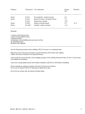
... counterclockwise until it drops down slightly. Fastener Thread size For component Torque Nm Remarks Screw Screw Screw Screw P 4x12 P 4x10 M 10x1 D 4x20 D 5.3x41 Pre-separator / engine housing Elbow connector / air guide shroud Spark plug / cylinder Ignition module/cylinder Cylinder / engine housing 2.0 1.6 12.0 4.5 11.0 1), 3) Remarks: 1) Screws with binding head 2) Micro-encapsulated screws 3) Waxed screws 4) Degrease crankshaft/flywheel and mount oil-free Q) QuickStop Super B) Quick chain adjuster Use the following procedure when refitting a DG or...
... counterclockwise until it drops down slightly. Fastener Thread size For component Torque Nm Remarks Screw Screw Screw Screw P 4x12 P 4x10 M 10x1 D 4x20 D 5.3x41 Pre-separator / engine housing Elbow connector / air guide shroud Spark plug / cylinder Ignition module/cylinder Cylinder / engine housing 2.0 1.6 12.0 4.5 11.0 1), 3) Remarks: 1) Screws with binding head 2) Micro-encapsulated screws 3) Waxed screws 4) Degrease crankshaft/flywheel and mount oil-free Q) QuickStop Super B) Quick chain adjuster Use the following procedure when refitting a DG or...

Instruction Manual
Page 13
... Install new spring housing 12 MS 231, MS 231 C, MS 251, MS 251 C not vertically Fit new starter rope Normal wear Fit new starter rope Starter rope does not rewind Rewind spring very dirty or corroded Insufficient spring tension Rewind spring broken Clean or replace rewind spring Check rewind spring and increase tension Fit new rewind spring Starter rope cannot be pulled out Spring overtensioned far enough Check rewind spring and reduce tension Starter rope can be pulled out almost without resistance (crankshaft does not turn) ...Models with ErgoStart Guide...
... Install new spring housing 12 MS 231, MS 231 C, MS 251, MS 251 C not vertically Fit new starter rope Normal wear Fit new starter rope Starter rope does not rewind Rewind spring very dirty or corroded Insufficient spring tension Rewind spring broken Clean or replace rewind spring Check rewind spring and increase tension Fit new rewind spring Starter rope cannot be pulled out Spring overtensioned far enough Check rewind spring and reduce tension Starter rope can be pulled out almost without resistance (crankshaft does not turn) ...Models with ErgoStart Guide...

Instruction Manual
Page 15
... firmly onto spark plug and fit new spring if necessary Spark plug sooted, smeared with oil Clean the spark plug or replace if necessary. too much oil Use correct mixture of fuel and oil Incorrect air gap between ignition Set air gap correctly module and flywheel Flywheel cracked or damaged or pole shoes have turned blue Install new flywheel Ignition timing wrong, flywheel out of the spark plug, clean or replace spark plug if necessary. 14 MS 231, MS 231 C, MS 251, MS 251 C If sooting keeps recurring, check air filter Fuel/oil mixture - Check operation of adjustment -
... firmly onto spark plug and fit new spring if necessary Spark plug sooted, smeared with oil Clean the spark plug or replace if necessary. too much oil Use correct mixture of fuel and oil Incorrect air gap between ignition Set air gap correctly module and flywheel Flywheel cracked or damaged or pole shoes have turned blue Install new flywheel Ignition timing wrong, flywheel out of the spark plug, clean or replace spark plug if necessary. 14 MS 231, MS 231 C, MS 251, MS 251 C If sooting keeps recurring, check air filter Fuel/oil mixture - Check operation of adjustment -
Instruction Manual
Page 17
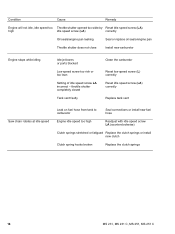
...lean Setting of idle speed screw LA incorrect - throttle shutter completely closed Tank vent faulty Clean the carburetor Reset low speed screw (L) correctly Reset idle speed screw (LA) correctly Replace tank vent Saw chain rotates at idle speed Leak on fuel hose from tank to carburetor Seal connections or install new fuel hose Engine idle speed too high Readjust with idle speed screw LA (counterclockwise) Clutch springs stretched or fatigued Replace the clutch springs or install new clutch Clutch spring hooks broken Replace the clutch springs 16 MS 231, MS 231 C, MS 251, MS 251 C
...lean Setting of idle speed screw LA incorrect - throttle shutter completely closed Tank vent faulty Clean the carburetor Reset low speed screw (L) correctly Reset idle speed screw (LA) correctly Replace tank vent Saw chain rotates at idle speed Leak on fuel hose from tank to carburetor Seal connections or install new fuel hose Engine idle speed too high Readjust with idle speed screw LA (counterclockwise) Clutch springs stretched or fatigued Replace the clutch springs or install new clutch Clutch spring hooks broken Replace the clutch springs 16 MS 231, MS 231 C, MS 251, MS 251 C
Instruction Manual
Page 19
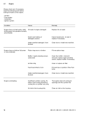
... Oil seals in fan housing dirty Clean air inlet on the engine: - Engine does not deliver full power Piston rings worn or broken or runs erratically Muffler / spark arresting screen carbonized Air filter dirty Fuel hose kinked or torn Intake manifold damaged / bore blocked Fit new piston rings Clean the muffler (inlet and exhaust), replace spark arresting screen, replace muffler if necessary Clean or replace air filter Fit new hose or position it free from kinks Clean bore or install new manifold. Engine...
... Oil seals in fan housing dirty Clean air inlet on the engine: - Engine does not deliver full power Piston rings worn or broken or runs erratically Muffler / spark arresting screen carbonized Air filter dirty Fuel hose kinked or torn Intake manifold damaged / bore blocked Fit new piston rings Clean the muffler (inlet and exhaust), replace spark arresting screen, replace muffler if necessary Clean or replace air filter Fit new hose or position it free from kinks Clean bore or install new manifold. Engine...
Instruction Manual
Page 24
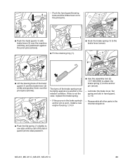
.... If the groove in hand guard, b 14 - - If this is worn, install a new engine housing, b 6.6 2310RA028 TG : Use the assembly tool (2) 1117 890 0900 to attach the brake spring (1) to the brake lever (arrow). 1 2 2310RA030 TG 1 TOP 2310RA025 TG : Lift the bearing boss of the hand guard (1) and the brake lever (2) a little and position them over the pivot pins (arrows). 1 The turns of the brake spring must be tightly against one...
.... If the groove in hand guard, b 14 - - If this is worn, install a new engine housing, b 6.6 2310RA028 TG : Use the assembly tool (2) 1117 890 0900 to attach the brake spring (1) to the brake lever (arrow). 1 2 2310RA030 TG 1 TOP 2310RA025 TG : Lift the bearing boss of the hand guard (1) and the brake lever (2) a little and position them over the pivot pins (arrows). 1 The turns of the brake spring must be tightly against one...
Instruction Manual
Page 25
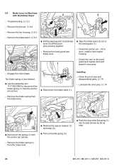
... brake band, b 5.2 1 1 TOP : Pull the hand guard (1) and brake lever (2) off the pivot pins (arrows) together. - Remove the brake spring (1) from the anchor pin (arrow). - TOP 2310RA031 TG - Troubleshooting, b 3.2 - if it is now relaxed. : Use the assembly tool 1117 890 0900 to disconnect the brake spring (1) from the brake lever. 2 2310RA034 TG Installing - The brake spring is worn, install a new engine housing. - Remove the brake spring from the anchor pin (arrow). : Disconnect the brake cable (1). - Clean the pivot pins and disassembled parts, b 14 - Check...
... brake band, b 5.2 1 1 TOP : Pull the hand guard (1) and brake lever (2) off the pivot pins (arrows) together. - Remove the brake spring (1) from the anchor pin (arrow). - TOP 2310RA031 TG - Troubleshooting, b 3.2 - if it is now relaxed. : Use the assembly tool 1117 890 0900 to disconnect the brake spring (1) from the brake lever. 2 2310RA034 TG Installing - The brake spring is worn, install a new engine housing. - Remove the brake spring from the anchor pin (arrow). : Disconnect the brake cable (1). - Clean the pivot pins and disassembled parts, b 14 - Check...

Instruction Manual
Page 27
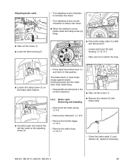
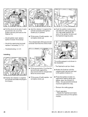
... lockout lever (1) to the brake lever (arrow). 26 MS 231, MS 231 C, MS 251, MS 251 C If this is necessary to disconnect the brake spring (1) from the anchor pin (arrow). - Troubleshooting, b 3.2 - Checking condition and free travel is visible. : Attach the spring (1) to the anchor pin (2). : Use the assembly tool 1117 890 0900 to guarantee correct operation of free travel must rotate freely. - Free travel - If the groove in the brake spring's anchor pin is worn, install a new engine housing, b 6.6 1 If problems occur...
... lockout lever (1) to the brake lever (arrow). 26 MS 231, MS 231 C, MS 251, MS 251 C If this is necessary to disconnect the brake spring (1) from the anchor pin (arrow). - Troubleshooting, b 3.2 - Checking condition and free travel is visible. : Attach the spring (1) to the anchor pin (2). : Use the assembly tool 1117 890 0900 to guarantee correct operation of free travel must rotate freely. - Free travel - If the groove in the brake spring's anchor pin is worn, install a new engine housing, b 6.6 1 If problems occur...
Instruction Manual
Page 28
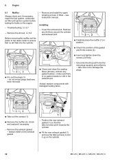
... (1) must locate snugly against engine housing (arrows) and the clutch drum must rotate freely. 2 1 - Remove the carburetor, b 12.5 - Take care not to increase free travel on the adjusting screw (1). 2310RA051 TG 2310RA050 TG : Pull out the brake cable (1) a little and disconnect it in the reverse sequence. : Take out the screw (1). 5.4.2 Brake cable Removing and Installing : Remove the retainer (2) with brake cable. - Remove the switch lever, b 10.3.1 2 - Check the brake cable (1) and retainer (2), replace if necessary MS 231, MS 231 C, MS 251, MS 251...
... (1) must locate snugly against engine housing (arrows) and the clutch drum must rotate freely. 2 1 - Remove the carburetor, b 12.5 - Take care not to increase free travel on the adjusting screw (1). 2310RA051 TG 2310RA050 TG : Pull out the brake cable (1) a little and disconnect it in the reverse sequence. : Take out the screw (1). 5.4.2 Brake cable Removing and Installing : Remove the retainer (2) with brake cable. - Remove the switch lever, b 10.3.1 2 - Check the brake cable (1) and retainer (2), replace if necessary MS 231, MS 231 C, MS 251, MS 251...
Instruction Manual
Page 33
... into the cylinder. - take care not to push home the new plugs squarely and uniformly - 6. Engine 2310RA071 TG 6.1 Muffler Always check and, if necessary, repair the fuel system, carburetor, air filter and ignition system before looking for faults on the cylinder. 32 MS 231, MS 231 C, MS 251, MS 251 C Use a blunt tool to damage the plugs. Remove any gasket residue - Position the new exhaust gasket (1) so that the tabs (arrows) point towards...
... into the cylinder. - take care not to push home the new plugs squarely and uniformly - 6. Engine 2310RA071 TG 6.1 Muffler Always check and, if necessary, repair the fuel system, carburetor, air filter and ignition system before looking for faults on the cylinder. 32 MS 231, MS 231 C, MS 251, MS 251 C Use a blunt tool to damage the plugs. Remove any gasket residue - Position the new exhaust gasket (1) so that the tabs (arrows) point towards...
Instruction Manual
Page 47
... the ignition module. 46 MS 231, MS 231 C, MS 251, MS 251 C the ground wire terminal must turn freely. : Rotate the flywheel until the magnet poles (arrows) are next to the bosses. 2 : Fit the ground wire (1) so that the terminal butts against the setting gauge and tighten down the screws (2) firmly - The setting gauge is not shown in position. : Fit the screw (3) with washer - Check the spark plug boot and replace...
... the ignition module. 46 MS 231, MS 231 C, MS 251, MS 251 C the ground wire terminal must turn freely. : Rotate the flywheel until the magnet poles (arrows) are next to the bosses. 2 : Fit the ground wire (1) so that the terminal butts against the setting gauge and tighten down the screws (2) firmly - The setting gauge is not shown in position. : Fit the screw (3) with washer - Check the spark plug boot and replace...

Instruction Manual
Page 49
... terminal (1). Before starting the test, install a new spark plug in the cylinder and tighten it in the tester's window (3). If no spark is in the center of the leg spring into the spark plug boot. 48 MS 231, MS 231 C, MS 251, MS 251 C High voltage - Remove the spark plug boot and pull the ignition lead out of the ignition lead's insulation, about 2 mm, see window (3). - risk of electric shock. : Use suitable pliers to...
... terminal (1). Before starting the test, install a new spark plug in the cylinder and tighten it in the tester's window (3). If no spark is in the center of the leg spring into the spark plug boot. 48 MS 231, MS 231 C, MS 251, MS 251 C High voltage - Remove the spark plug boot and pull the ignition lead out of the ignition lead's insulation, about 2 mm, see window (3). - risk of electric shock. : Use suitable pliers to...
Instruction Manual
Page 96
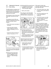
... speed screw L and high speed screw H - As soon as a maximum engine speed of clarity the adjusting screws are installed, the adjusting screws fitted and the new limiter cap preinstalled. - Inspect the spark arresting screen (if fitted) and clean or replace if necessary, b 3.7 or b 6.1 - Use the idle speed screw (LA) to set engine speed to 3,300 rpm. 4. Use the low speed screw (L) to set the engine speed again to 2,800 rpm. 5. This speed cannot be fitted on the exposed carburetor. : Starting with step 1. 3. Check the air filter and clean...
... speed screw L and high speed screw H - As soon as a maximum engine speed of clarity the adjusting screws are installed, the adjusting screws fitted and the new limiter cap preinstalled. - Inspect the spark arresting screen (if fitted) and clean or replace if necessary, b 3.7 or b 6.1 - Use the idle speed screw (LA) to set engine speed to 3,300 rpm. 4. Use the low speed screw (L) to set the engine speed again to 2,800 rpm. 5. This speed cannot be fitted on the exposed carburetor. : Starting with step 1. 3. Check the air filter and clean...
Instruction Manual
Page 97
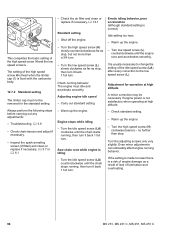
... smoothly. Turn the idle speed screw (LA) counterclockwise until the chain starts running , then turn it back 1 full turn . Turn the high speed screw (H) clockwise (leaner) - Troubleshooting, b 3.6 - Check running behavior. no further than stop , but not more than a 3/4 turn . If the setting is made too lean there is not satisfactory when operating at high altitude A minor correction may be removed for operation at high altitude. - Inspect the spark arresting screen (if fitted) and clean or replace if...
... smoothly. Turn the idle speed screw (LA) counterclockwise until the chain starts running , then turn it back 1 full turn . Turn the high speed screw (H) clockwise (leaner) - Troubleshooting, b 3.6 - Check running behavior. no further than stop , but not more than a 3/4 turn . If the setting is made too lean there is not satisfactory when operating at high altitude A minor correction may be removed for operation at high altitude. - Inspect the spark arresting screen (if fitted) and clean or replace if...

Instruction Manual
Page 108
... short nipple (5) and the carburetor connector (6). - Reassemble all other parts in the reverse sequence. 2310RA404 TG 1 : Disconnect the fuel suction hose (1) and fuel return hose (2) from the nipples (arrows). - Install the carburetor, b 12.5 12.11.4 Manual Fuel Pump Installing - Check operation of manual fuel pump, b 12.11.4 - Reassemble all other parts in the reverse sequence. Check operation - fuel must flow when the fuel pump is operated. - MS 231, MS 231 C, MS 251, MS 251 C 107 - Install the air guide shroud, b 12.4.1 -
... short nipple (5) and the carburetor connector (6). - Reassemble all other parts in the reverse sequence. 2310RA404 TG 1 : Disconnect the fuel suction hose (1) and fuel return hose (2) from the nipples (arrows). - Install the carburetor, b 12.5 12.11.4 Manual Fuel Pump Installing - Check operation of manual fuel pump, b 12.11.4 - Reassemble all other parts in the reverse sequence. Check operation - fuel must flow when the fuel pump is operated. - MS 231, MS 231 C, MS 251, MS 251 C 107 - Install the air guide shroud, b 12.4.1 -

Instruction Manual
Page 111
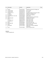
... socket screws with torque wrench Lowering tank housing, maintaining clearance Removing and installing piston pin Adjusting air gap between the ignition module and flywheel Installing rewind spring Attaching springs Leakage Test Protecting the oil seal (clutch side) Installing oil seal (clutch side/ignition side) Spark plug 1) Protecting the oil seal (ignition side) Clamping machine to assembly stand Testing ignition system Testing ignition system 110 MS 231, MS 231 C, MS 251, MS 251 C Description 1 Carburetor and engine tester - Special Servicing Tools New Special Tools No...
... socket screws with torque wrench Lowering tank housing, maintaining clearance Removing and installing piston pin Adjusting air gap between the ignition module and flywheel Installing rewind spring Attaching springs Leakage Test Protecting the oil seal (clutch side) Installing oil seal (clutch side/ignition side) Spark plug 1) Protecting the oil seal (ignition side) Clamping machine to assembly stand Testing ignition system Testing ignition system 110 MS 231, MS 231 C, MS 251, MS 251 C Description 1 Carburetor and engine tester - Special Servicing Tools New Special Tools No...
Instruction Manual
Page 112
... in piston Sleeve for installing tool 10 Adjusting the carburetor IS-P screws Detaching springs on for screwdriver (adjusting carburetor) Removing pickup body Remarks: 1) Use for repairs Removing oil seals Removing oil seals Removing oil seals Pull off the limiter cap. MS 231, MS 231 C, MS 251, MS 251 C 111 Jaws (No. 3.1) - Removing bar mounting studs Removing flywheel Add-on clutch shoes Holding saw for releasing only. Sleeve 23 Screwdriver 24 Screwdriver bit, T 27 x 150 25 Hook 26 Assembly stand 27 Puller...
... in piston Sleeve for installing tool 10 Adjusting the carburetor IS-P screws Detaching springs on for screwdriver (adjusting carburetor) Removing pickup body Remarks: 1) Use for repairs Removing oil seals Removing oil seals Removing oil seals Pull off the limiter cap. MS 231, MS 231 C, MS 251, MS 251 C 111 Jaws (No. 3.1) - Removing bar mounting studs Removing flywheel Add-on clutch shoes Holding saw for releasing only. Sleeve 23 Screwdriver 24 Screwdriver bit, T 27 x 150 25 Hook 26 Assembly stand 27 Puller...


