

Instruction Manual
Page 2
... AV Spring on Fuel Tank 66 AV Spring on Handlebar 67 Stop Buffers 68 Buffers on Machines with Manual Fuel Pump 85 12.5 Carburetor 88 12.5.1 Leakage Test 89 RA_737_00_01_01 MS 231, MS 231 C, MS 251, MS 251 C q © ANDREAS STIHL AG & Co. Chain Lubrication 78 11.1 Pickup Body 78 11.2 Oil Suction Hose 78 11.3 Oil Pump...
... AV Spring on Fuel Tank 66 AV Spring on Handlebar 67 Stop Buffers 68 Buffers on Machines with Manual Fuel Pump 85 12.5 Carburetor 88 12.5.1 Leakage Test 89 RA_737_00_01_01 MS 231, MS 231 C, MS 251, MS 251 C q © ANDREAS STIHL AG & Co. Chain Lubrication 78 11.1 Pickup Body 78 11.2 Oil Suction Hose 78 11.3 Oil Pump...
Instruction Manual
Page 3
Special Servicing Tools 110 14. Manual Fuel Pump 105 12.11.4 Manual Fuel Pump 107 12.11.5 Tank Housing 108 13. Contents 12.6 Servicing the Carburetor 90 12.6.1 Metering Diaphragm 90 12.6.2 Inlet Needle 90 12.6.3 Pump ... and Installing 100 12.11 Fuel Intake 101 12.11.1 Pickup Body 101 12.11.2 Fuel Hose 101 12.11.3 Fuel Hoses - Servicing Aids 112 2 MS 231, MS 231 C, MS 251, MS 251 C
Special Servicing Tools 110 14. Manual Fuel Pump 105 12.11.4 Manual Fuel Pump 107 12.11.5 Tank Housing 108 13. Contents 12.6 Servicing the Carburetor 90 12.6.1 Metering Diaphragm 90 12.6.2 Inlet Needle 90 12.6.3 Pump ... and Installing 100 12.11 Fuel Intake 101 12.11.1 Pickup Body 101 12.11.2 Fuel Hose 101 12.11.3 Fuel Hoses - Servicing Aids 112 2 MS 231, MS 231 C, MS 251, MS 251 C

Instruction Manual
Page 4
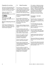
... locate the fault, consult the chapter on the machine, may have been introduced since they, depending on "Troubleshooting" and the "STIHL Service Training System" for greater clarity. Use the part numbers to check the part numbers of the illustrated parts lists while carrying ... bulletins are included in the illustration above the text - The screws must not be passed to this power tool. MS 231, MS 231 C, MS 251, MS 251 C 3 The manual lists all the repair and servicing procedures specific to third parties. The meanings are made considerably easier if the machine ...
... locate the fault, consult the chapter on the machine, may have been introduced since they, depending on "Troubleshooting" and the "STIHL Service Training System" for greater clarity. Use the part numbers to check the part numbers of the illustrated parts lists while carrying ... bulletins are included in the illustration above the text - The screws must not be passed to this power tool. MS 231, MS 231 C, MS 251, MS 251 C 3 The manual lists all the repair and servicing procedures specific to third parties. The meanings are made considerably easier if the machine ...
Instruction Manual
Page 5
..., MS 231 C, MS 251, MS 251 C Check disassembled parts for wear or damage before carrying out repairs or mounting the machine to the hose barbs, b 14. replace as the safety precautions and warnings in position - Avoid damaging the hose barb - do not use original STIHL replacement parts....a clean container and dispose of it properly in accordance with the shroud mounted in the instruction manual. Always wear suitable protective gloves for operations in this service manual. Do not cut open fuel hoses with threadlocking adhesive. Always install new hoses - Always replace ...
..., MS 231 C, MS 251, MS 251 C Check disassembled parts for wear or damage before carrying out repairs or mounting the machine to the hose barbs, b 14. replace as the safety precautions and warnings in position - Avoid damaging the hose barb - do not use original STIHL replacement parts....a clean container and dispose of it properly in accordance with the shroud mounted in the instruction manual. Always wear suitable protective gloves for operations in this service manual. Do not cut open fuel hoses with threadlocking adhesive. Always install new hoses - Always replace ...
Instruction Manual
Page 6
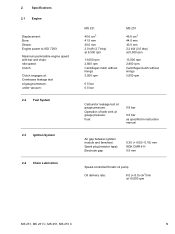
... mm 30.0 mm 2.0 kW (2.7 bhp) at 9,500 rpm 13,000 rpm 2,800 rpm Centrifugal clutch without linings 3,500 rpm 0.5 bar 0.5 bar MS 251 45.6 cm3 44.0 mm 30.0 mm 2.2 kW (3.0 bhp) at 9,500 rpm 13,000 rpm 2,800 rpm Centrifugal clutch without linings 3,500 rpm Carburetor...gauge pressure: Fuel: 0.8 bar 0.5 bar as specified in instruction manual Air gap between ignition module and fanwheel: Spark plug (resistor type): Electrode gap: 0.30 (+ 0.05/- 0.10) mm NGK CMR 6 H 0.5 mm Speed-controlled Ematic oil pump Oil delivery rate: 8.0 (+/3.0) cm3/min at 10,000 rpm MS 231, MS 231 C, MS 251, MS 251 C 5
... mm 30.0 mm 2.0 kW (2.7 bhp) at 9,500 rpm 13,000 rpm 2,800 rpm Centrifugal clutch without linings 3,500 rpm 0.5 bar 0.5 bar MS 251 45.6 cm3 44.0 mm 30.0 mm 2.2 kW (3.0 bhp) at 9,500 rpm 13,000 rpm 2,800 rpm Centrifugal clutch without linings 3,500 rpm Carburetor...gauge pressure: Fuel: 0.8 bar 0.5 bar as specified in instruction manual Air gap between ignition module and fanwheel: Spark plug (resistor type): Electrode gap: 0.30 (+ 0.05/- 0.10) mm NGK CMR 6 H 0.5 mm Speed-controlled Ematic oil pump Oil delivery rate: 8.0 (+/3.0) cm3/min at 10,000 rpm MS 231, MS 231 C, MS 251, MS 251 C 5
Instruction Manual
Page 20
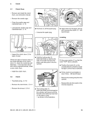
...- Lubricate the needle cage and crankshaft stub, b 14 1 : Pull boot (1) off the spark plug. - Reassemble all other parts in the illustration. MS 231, MS 231 C, MS 251, MS 251 C 19 lefthand thread. 2310RA004 TG 1 1 Installing TOP 5902RA018 TG 80% ! 100% - Remove the shroud, b 6.4 : The locking strip (1) ...piston and then push it down firmly - Remove the locking strip from the cylinder. - 4. Remove and install the clutch drum, see instruction manual. - Inspect the clutch drum (1) for signs of the original thickness, install a new clutch drum. - Install the clutch drum. : ...
...- Lubricate the needle cage and crankshaft stub, b 14 1 : Pull boot (1) off the spark plug. - Reassemble all other parts in the illustration. MS 231, MS 231 C, MS 251, MS 251 C 19 lefthand thread. 2310RA004 TG 1 1 Installing TOP 5902RA018 TG 80% ! 100% - Remove the shroud, b 6.4 : The locking strip (1) ...piston and then push it down firmly - Remove the locking strip from the cylinder. - 4. Remove and install the clutch drum, see instruction manual. - Inspect the clutch drum (1) for signs of the original thickness, install a new clutch drum. - Install the clutch drum. : ...
Instruction Manual
Page 21
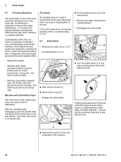
...standstill. Remove the clutch drum, b 4.1 - Remove the brake band without overstretching it from the underside of the machine. 20 MS 231, MS 231 C, MS 251, MS 251 C Engage the chain brake. Install a new brake band if there are noticeable signs of wear (large With the coasting brake ...time. to troubleshooting, b 3.2. Contamination (with QuickStop Super - With the chain brake activated (locked), open the throttle wide and activate the brake manually - If the chain brake does not operate properly, refer to an abrupt stop . : Take out the screws (1). : Remove the cover ...
...standstill. Remove the clutch drum, b 4.1 - Remove the brake band without overstretching it from the underside of the machine. 20 MS 231, MS 231 C, MS 251, MS 251 C Engage the chain brake. Install a new brake band if there are noticeable signs of wear (large With the coasting brake ...time. to troubleshooting, b 3.2. Contamination (with QuickStop Super - With the chain brake activated (locked), open the throttle wide and activate the brake manually - If the chain brake does not operate properly, refer to an abrupt stop . : Take out the screws (1). : Remove the cover ...
Instruction Manual
Page 29
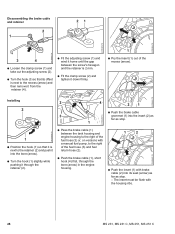
... retainer (2). 2310RA055 TG : Pass the brake cable (1) between the tank housing and engine housing to the right of the fuel hose (3) or, on versions with a manual fuel pump, to the retainer (2) and push it into the bore (arrow). : Turn the hook (1) slightly while pushing it down firmly. 1 : Pry the insert (1) out... return hose (2). : Push the brake cable (1), short hook (4) first, through the bore (arrow) in the engine housing. 1 2 : Push the insert (1) with the housing ribs. 28 MS 231, MS 231 C, MS 251, MS 251 C
... retainer (2). 2310RA055 TG : Pass the brake cable (1) between the tank housing and engine housing to the right of the fuel hose (3) or, on versions with a manual fuel pump, to the retainer (2) and push it into the bore (arrow). : Turn the hook (1) slightly while pushing it down firmly. 1 : Pry the insert (1) out... return hose (2). : Push the brake cable (1), short hook (4) first, through the bore (arrow) in the engine housing. 1 2 : Push the insert (1) with the housing ribs. 28 MS 231, MS 231 C, MS 251, MS 251 C
Instruction Manual
Page 33
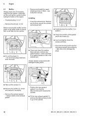
... 6.1 Muffler Always check and, if necessary, repair the fuel system, carburetor, air filter and ignition system before looking for faults on the cylinder. 32 MS 231, MS 231 C, MS 251, MS 251 C Remove the shroud, b 6.4 Before removing the muffler, set the piston to top dead center to line it up on the engine. - Remove and install... and fit the screws (2). : Insert and tighten down the screws (2) firmly. 2310RA069 TG 11 : Pry out the plugs (1) - Troubleshooting, b 3.7 - Remove any gasket residue - see instruction manual.
... 6.1 Muffler Always check and, if necessary, repair the fuel system, carburetor, air filter and ignition system before looking for faults on the cylinder. 32 MS 231, MS 231 C, MS 251, MS 251 C Remove the shroud, b 6.4 Before removing the muffler, set the piston to top dead center to line it up on the engine. - Remove and install... and fit the screws (2). : Insert and tighten down the screws (2) firmly. 2310RA069 TG 11 : Pry out the plugs (1) - Troubleshooting, b 3.7 - Remove any gasket residue - see instruction manual.
Instruction Manual
Page 72
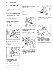
... the filter base and replace 2 The positions of the Master Control it and replace if necessary. Remove the choke rod, b 10.3.3 - MS 231, MS 231 C, MS 251, MS 251 C 71 Position filter base in the instruction manual. Remove the contact spring, b 7.7.4 1 2310RA162 TG 2 : Position the switch lever (1) in the carburetor box. - Installing 1 10.1.1 Removing and Installing - 10...
... the filter base and replace 2 The positions of the Master Control it and replace if necessary. Remove the choke rod, b 10.3.3 - MS 231, MS 231 C, MS 251, MS 251 C 71 Position filter base in the instruction manual. Remove the contact spring, b 7.7.4 1 2310RA162 TG 2 : Position the switch lever (1) in the carburetor box. - Installing 1 10.1.1 Removing and Installing - 10...
Instruction Manual
Page 78
Install the filter base, b 12.3 - MS 231, MS 231 C, MS 251, MS 251 C 77 Install the throttle trigger, b 10.2 1 1 2310RA294 TG 2310RA297 TG 2310RA199 TG : Remove the fuel hose (1). All models - Reassemble all other parts in the ...) in the direction of the rear handle. 1 2 : Fit the new fuel hose (1). Check the throttle rod and replace if necessary Installing 2 : Push the carburetor (1) with manual fuel pump 1 2310RA200 TG 2 1 2310RA295 TG 2310RA298 TG : Carefully pull the carburetor (1) off the studs - All models 1 : Pass the throttle cable (1) through the opening ...
Install the filter base, b 12.3 - MS 231, MS 231 C, MS 251, MS 251 C 77 Install the throttle trigger, b 10.2 1 1 2310RA294 TG 2310RA297 TG 2310RA199 TG : Remove the fuel hose (1). All models - Reassemble all other parts in the ...) in the direction of the rear handle. 1 2 : Fit the new fuel hose (1). Check the throttle rod and replace if necessary Installing 2 : Push the carburetor (1) with manual fuel pump 1 2310RA200 TG 2 1 2310RA295 TG 2310RA298 TG : Carefully pull the carburetor (1) off the studs - All models 1 : Pass the throttle cable (1) through the opening ...
Instruction Manual
Page 82
.... 12.3 Filter Base - see instruction manual. - Remove the choke rod, b 10.3.3 - Remove the baffle, b 12.2 2 1 2310RA197 TG 2310RA196 TG 1 2 : Pry the filter base (1) out of the buffer (2). 2310RA195 TG : Pull the short circuit wire (1) and ground wire (2) out of the buffer (2). - 2310RA198 TG 12. MS 231, MS 231 C, MS 251, MS 251 C 81 See also Troubleshooting, b 3.6, b 3.7 1 - Reassemble...
.... 12.3 Filter Base - see instruction manual. - Remove the choke rod, b 10.3.3 - Remove the baffle, b 12.2 2 1 2310RA197 TG 2310RA196 TG 1 2 : Pry the filter base (1) out of the buffer (2). 2310RA195 TG : Pull the short circuit wire (1) and ground wire (2) out of the buffer (2). - 2310RA198 TG 12. MS 231, MS 231 C, MS 251, MS 251 C 81 See also Troubleshooting, b 3.6, b 3.7 1 - Reassemble...
Instruction Manual
Page 86
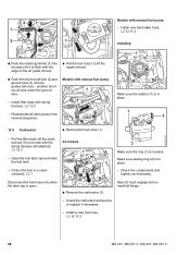
... and pull the air guide shroud away at the same time. 2310RA338 TG MS 231, MS 231 C, MS 251, MS 251 C 85 Pull the filter base off the spark plug. : Take out the screw (1). : Remove the connector (2) and disconnect it to one side with Manual Fuel 2 Pump 1 - Pull the boot off the studs and put it from...
... and pull the air guide shroud away at the same time. 2310RA338 TG MS 231, MS 231 C, MS 251, MS 251 C 85 Pull the filter base off the spark plug. : Take out the screw (1). : Remove the connector (2) and disconnect it to one side with Manual Fuel 2 Pump 1 - Pull the boot off the studs and put it from...
Instruction Manual
Page 89
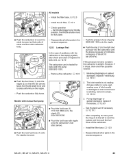
... the ring (1) is open. : Remove the carburetor (1). Collect the fuel in the reverse sequence. 2310RA351 TG Models with manual fuel pump 1 - Install a new fuel hose, b 12.11.2 2310RA353 TG 88 MS 231, MS 231 C, MS 251, MS 251 C position short circuit wire under the ground wire. Install filter base with the wiring harness still attached, b 12.3 - Open...
... the ring (1) is open. : Remove the carburetor (1). Collect the fuel in the reverse sequence. 2310RA351 TG Models with manual fuel pump 1 - Install a new fuel hose, b 12.11.2 2310RA353 TG 88 MS 231, MS 231 C, MS 251, MS 251 C position short circuit wire under the ground wire. Install filter base with the wiring harness still attached, b 12.3 - Open...
Instruction Manual
Page 90
... case of inlet needle is damaged or inlet control lever is airtight. Metering diaphragm or gasket damaged, replace if necessary, b 12.6.1 1 2. MS 231, MS 231 C, MS 251, MS 251 C 89 Reassemble all other parts in the - The inlet needle is not sealing (foreign matter in the reverse sequence. 1 All models 2... 12.5 1. Test the tank vent if necessary, b 12.10.1 - Reassemble all other parts in valve seat, sealing cone of problems with manual fuel pump 1 : Push the new fuel hose (1) onto the nipples (arrows). 2310RA356 TG 2310RA355 TG 2310RA354 TG 2310RA255 TG -
... case of inlet needle is damaged or inlet control lever is airtight. Metering diaphragm or gasket damaged, replace if necessary, b 12.6.1 1 2. MS 231, MS 231 C, MS 251, MS 251 C 89 Reassemble all other parts in the - The inlet needle is not sealing (foreign matter in the reverse sequence. 1 All models 2... 12.5 1. Test the tank vent if necessary, b 12.10.1 - Reassemble all other parts in valve seat, sealing cone of problems with manual fuel pump 1 : Push the new fuel hose (1) onto the nipples (arrows). 2310RA356 TG 2310RA355 TG 2310RA354 TG 2310RA255 TG -
Instruction Manual
Page 91
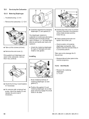
... Oring (arrow). - Check position of fatigue. The diaphragm material is subjected to the carburetor, remove them down the screws firmly in the tabs. 90 MS 231, MS 231 C, MS 251, MS 251 C Install a new gasket. Check the metering diaphragm for signs of metering diaphragm (2) and gasket (1). : Position the gasket (1) and metering diaphragm (2) ... down yet. - Remove the metering diaphragm, b 12.6.1 2310RA257 TG 2310RA259 TG 1 : Check the O-ring (1) and replace it if necessary : On versions with a manual fuel pump, check the nipple (2) and replace the end cover if necessary. -
... Oring (arrow). - Check position of fatigue. The diaphragm material is subjected to the carburetor, remove them down the screws firmly in the tabs. 90 MS 231, MS 231 C, MS 251, MS 251 C Install a new gasket. Check the metering diaphragm for signs of metering diaphragm (2) and gasket (1). : Position the gasket (1) and metering diaphragm (2) ... down yet. - Remove the metering diaphragm, b 12.6.1 2310RA257 TG 2310RA259 TG 1 : Check the O-ring (1) and replace it if necessary : On versions with a manual fuel pump, check the nipple (2) and replace the end cover if necessary. -
Instruction Manual
Page 99
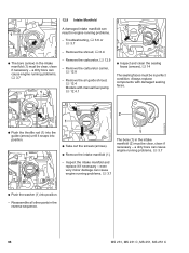
Troubleshooting, b 3.6 or b 3.7 - Always replace components with manual fuel pump, b 12.4.1 : Inspect and clean the sealing faces (arrows), b 14 The sealing faces must be clear, clean if necessary - even very minor ... 1 : The bore (arrow) in the intake manifold (1) must be in perfect condition. Remove the shroud, b 6.4 - a dirty bore can result in the reverse sequence. 98 MS 231, MS 231 C, MS 251, MS 251 C Remove the carburetor carrier, b 12.8 - Remove the carburetor, b 12.5 - Remove the air guide shroud, b 12.4 Models with damaged sealing faces. 2310RA287 TG 2 1 ...
Troubleshooting, b 3.6 or b 3.7 - Always replace components with manual fuel pump, b 12.4.1 : Inspect and clean the sealing faces (arrows), b 14 The sealing faces must be clear, clean if necessary - even very minor ... 1 : The bore (arrow) in the intake manifold (1) must be in perfect condition. Remove the shroud, b 6.4 - a dirty bore can result in the reverse sequence. 98 MS 231, MS 231 C, MS 251, MS 251 C Remove the carburetor carrier, b 12.8 - Remove the carburetor, b 12.5 - Remove the air guide shroud, b 12.4 Models with damaged sealing faces. 2310RA287 TG 2 1 ...
Instruction Manual
Page 100
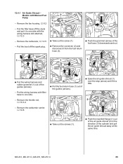
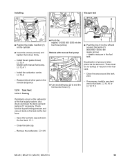
Models with manual fuel pump, b 12.4.1 - Close the tank cap. - Reassemble all other parts in the fuel tank. Installing Vacuum test 2 1 2310RA361 TG : Position the intake manifold (1) on ... tighten them down firmly. - Install the carburetor carrier, b 12.8 - Equalization of vacuum in the fuel tank. - Remove the carburetor, b 12.5 MS 231, MS 231 C, MS 251, MS 251 C 99 Install the air guide shroud, b 12.4 Models with manual fuel pump 1 2 : Use a suitable plug (2) to seal the fuel suction hose (1). 2310RA362 TG 1 : Push the ring (1) to the left...
Models with manual fuel pump, b 12.4.1 - Close the tank cap. - Reassemble all other parts in the fuel tank. Installing Vacuum test 2 1 2310RA361 TG : Position the intake manifold (1) on ... tighten them down firmly. - Install the carburetor carrier, b 12.8 - Equalization of vacuum in the fuel tank. - Remove the carburetor, b 12.5 MS 231, MS 231 C, MS 251, MS 251 C 99 Install the air guide shroud, b 12.4 Models with manual fuel pump 1 2 : Use a suitable plug (2) to seal the fuel suction hose (1). 2310RA362 TG 1 : Push the ring (1) to the left...
Instruction Manual
Page 102
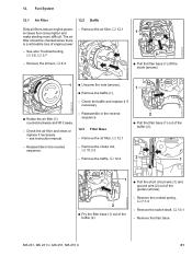
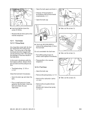
... the pickup body (1), check it . - Remove the air guide shroud, b 12.4 Models with minute particles of the filter eventually become clogged with manual fuel pump, b 12.4.1 2310RA374 TG MS 231, MS 231 C, MS 251, MS 251 C 101 Remove the carburetor carrier, b 12.8 1 : Take out the screws (1). - Open the tank again and drain it and replace if necessary...
... the pickup body (1), check it . - Remove the air guide shroud, b 12.4 Models with minute particles of the filter eventually become clogged with manual fuel pump, b 12.4.1 2310RA374 TG MS 231, MS 231 C, MS 251, MS 251 C 101 Remove the carburetor carrier, b 12.8 1 : Take out the screws (1). - Open the tank again and drain it and replace if necessary...
Instruction Manual
Page 105
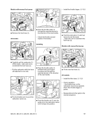
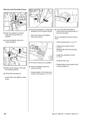
... the screws and tighten them down the screw (2) firmly. - Fit the pickup body, b 12.11.1 2 2 1 1 - Insert screw and tighten it in the reverse sequence. 104 MS 231, MS 231 C, MS 251, MS 251 C Machines with manual fuel pump, b 12.4.1 - Close the tank cap. - Do not overstretch the fuel suction hose. -
... the screws and tighten them down the screw (2) firmly. - Fit the pickup body, b 12.11.1 2 2 1 1 - Insert screw and tighten it in the reverse sequence. 104 MS 231, MS 231 C, MS 251, MS 251 C Machines with manual fuel pump, b 12.4.1 - Close the tank cap. - Do not overstretch the fuel suction hose. -


