

Product Instruction Manual
Page 30
...idle adjustment X X Carburetor Readjust idle X Readjust electrode gap X Spark plug Replace after every 100 operating hours Cooling inlets Visual inspection Clean X X Valve clearance Check and adjust if necessary after 139 hours of operation X Combustion chamber Decoke after first 139 hours of operating, then every 150 hours X Sparl... screws and nuts (not adjusting screws) Retighten X Antivibration elements Check X Have replaced by dealer1) X X 28 BR 500, BR 550, BR 600 English Maintenance and Care The following intervals apply to normal operating conditions only.
...idle adjustment X X Carburetor Readjust idle X Readjust electrode gap X Spark plug Replace after every 100 operating hours Cooling inlets Visual inspection Clean X X Valve clearance Check and adjust if necessary after 139 hours of operation X Combustion chamber Decoke after first 139 hours of operating, then every 150 hours X Sparl... screws and nuts (not adjusting screws) Retighten X Antivibration elements Check X Have replaced by dealer1) X X 28 BR 500, BR 550, BR 600 English Maintenance and Care The following intervals apply to normal operating conditions only.
Technical Guide
Page 9
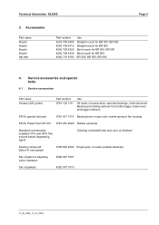
..., chain tensioner Bearing and sliding surfaces for throttle trigger, brake lever and trigger interlock STIHL special lubricant 0781 417 1315 Bearing bore in rope rotor, rewind spring in fan housing STIHL Press Fluid OH 723 0781 957 9000 Rubber elements Standard commercially available CFC and HFC-...number 4282 708 6300 4282 708 6310 4282 708 6320 4282 708 6330 4282 710 9100 Use Straight nozzle for BR 500, BR 550 Straight nozzle for BR 600 Bent nozzle for BR 500, BR 550 Bent nozzle for adjusting valve clearance 4282 007 1001 Set of parts for BR 600 BR 500, BR 550, BR 600 Page 9 4.
..., chain tensioner Bearing and sliding surfaces for throttle trigger, brake lever and trigger interlock STIHL special lubricant 0781 417 1315 Bearing bore in rope rotor, rewind spring in fan housing STIHL Press Fluid OH 723 0781 957 9000 Rubber elements Standard commercially available CFC and HFC-...number 4282 708 6300 4282 708 6310 4282 708 6320 4282 708 6330 4282 710 9100 Use Straight nozzle for BR 500, BR 550 Straight nozzle for BR 600 Bent nozzle for BR 500, BR 550 Bent nozzle for adjusting valve clearance 4282 007 1001 Set of parts for BR 600 BR 500, BR 550, BR 600 Page 9 4.
Technical Guide
Page 13
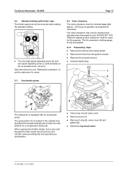
...007 1001 "Parts for adjusting valve clearance" must be used for users. 5.4 Valve clearance The valve clearance must be checked once after approx. 139 hours of operation and adjusted if necessary. The pump piston (1) is located in the idle position by a compression spring (3). Clean area around valve cover . Remove O-ring (2), valve cover (3) and gasket (4) ...rewind starter . The kit comprises a setting gauge, O-ring and gasket. 5.4.1 Preparatory steps . Remove the lines from the ignition module . The valve clearance may only be removed when making the standard setting. .
...007 1001 "Parts for adjusting valve clearance" must be used for users. 5.4 Valve clearance The valve clearance must be checked once after approx. 139 hours of operation and adjusted if necessary. The pump piston (1) is located in the idle position by a compression spring (3). Clean area around valve cover . Remove O-ring (2), valve cover (3) and gasket (4) ...rewind starter . The kit comprises a setting gauge, O-ring and gasket. 5.4.1 Preparatory steps . Remove the lines from the ignition module . The valve clearance may only be removed when making the standard setting. .
Technical Guide
Page 14
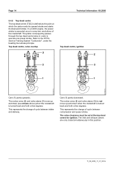
... a 4-MIX engine, the power stroke is defined as the point at the top dead centre for ignition. Cam (1) points downward. The valve clearance must be set at which the piston ends its upward stroke and starts its downward stroke. This represents the change of cycle between intake and... and power stroke. Refer to execute one power stroke. The piston consequently passes through the top dead centre twice in order to the STIHL Service Training System "Carburetor", under the heading four-stroke principle. Page 14 Technical Information 08.2005 5.4.2 Top dead centre The top dead...
... a 4-MIX engine, the power stroke is defined as the point at the top dead centre for ignition. Cam (1) points downward. The valve clearance must be set at which the piston ends its upward stroke and starts its downward stroke. This represents the change of cycle between intake and... and power stroke. Refer to execute one power stroke. The piston consequently passes through the top dead centre twice in order to the STIHL Service Training System "Carburetor", under the heading four-stroke principle. Page 14 Technical Information 08.2005 5.4.2 Top dead centre The top dead...
Technical Guide
Page 15
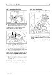
...is flush with the ignition coil. TI_08_2005_11_01_02.fm the setting gauge must produce a slight suction effect when it is pulled through The valve clearance must be adjusted if it clockwise again until the tip of the flywheel is found to be too large or too small. .... Rotate the crankshaft once more until the tip of the flywheel is now in order to "Check the valve clearance" and "Set the valve clearance". . Insert setting gauge (1) between rocker arm (2) and valve stem (3) - Turn the crankshaft back anticlockwise approx.1/4 turn and then slowly turn it is lined up ...
...is flush with the ignition coil. TI_08_2005_11_01_02.fm the setting gauge must produce a slight suction effect when it is pulled through The valve clearance must be adjusted if it clockwise again until the tip of the flywheel is found to be too large or too small. .... Rotate the crankshaft once more until the tip of the flywheel is now in order to "Check the valve clearance" and "Set the valve clearance". . Insert setting gauge (1) between rocker arm (2) and valve stem (3) - Turn the crankshaft back anticlockwise approx.1/4 turn and then slowly turn it is lined up ...

Technical Guide
Page 16
... screw with the ignition coil. . Switch off engine . Check engine does not leak TI_08_2005_11_01_02.fm Turn nut (2) clockwise to reduce the valve clearance or anticlockwise to increase it warm up . Start engine and let it - the setting gauge must produce a slight suction effect when it... is flush with a torque of the flywheel is pulled through . Check the valve clearance again and re-adjust if necessary . Fit gasket (1) in spark plug boot . Fit starter cover and tighten down screws . Rotate the crankshaft...
... screw with the ignition coil. . Switch off engine . Check engine does not leak TI_08_2005_11_01_02.fm Turn nut (2) clockwise to reduce the valve clearance or anticlockwise to increase it warm up . Start engine and let it - the setting gauge must produce a slight suction effect when it... is flush with a torque of the flywheel is pulled through . Check the valve clearance again and re-adjust if necessary . Fit gasket (1) in spark plug boot . Fit starter cover and tighten down screws . Rotate the crankshaft...

Technical Guide
Page 17
.... Fingers and other body parts must be at least 1 cm away from the spark plug, and screw out the spark plug. . Check valve clearance, set if necessary and recheck the compression If the compression is under 7.5 bar . Technical Information 08.2005 Page 17 5.5 Test the compression ...forcefully (min. 1,000 rpm) as when starting. . the target is 7.5 ... 8.5 bar If the compression is still under 7.5 bar . Check the cylinder, valve seat, piston and piston rings for the spark gap to approx. 2 mm. Affix the ground terminal (2) to the high voltage terminal (1). . Set the knob...
.... Fingers and other body parts must be at least 1 cm away from the spark plug, and screw out the spark plug. . Check valve clearance, set if necessary and recheck the compression If the compression is under 7.5 bar . Technical Information 08.2005 Page 17 5.5 Test the compression ...forcefully (min. 1,000 rpm) as when starting. . the target is 7.5 ... 8.5 bar If the compression is still under 7.5 bar . Check the cylinder, valve seat, piston and piston rings for the spark gap to approx. 2 mm. Affix the ground terminal (2) to the high voltage terminal (1). . Set the knob...
Technical Guide
Page 22
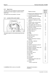
... tube 19 Replace gearhead or bearing housing 20 Limit stop or deflector 21 Drive shaft 22 Fuel tank 23 Test the compression pressure 24 Set valve clearance 25 Replace crankcase, bottom half 26 Replace crankshaft 27 Replace cylinder, piston 28 Oil supply 29 Oil pump, trial run 30 Back plate 31 Strap... hose with nozzle and control handle 35 Arrester * Trial run under load BR 500 BR 550 BR 600 60 100 100 - 40 - 15 15 10 30 10 10 - 10 5 10 - - - - - 10 10 10 150 160 180 - - 5 5 50 30 30 30 © ANDREAS STIHL AG & Co. Page 22 Technical Information 08.2005 5.10 Repair times The...
... tube 19 Replace gearhead or bearing housing 20 Limit stop or deflector 21 Drive shaft 22 Fuel tank 23 Test the compression pressure 24 Set valve clearance 25 Replace crankcase, bottom half 26 Replace crankshaft 27 Replace cylinder, piston 28 Oil supply 29 Oil pump, trial run 30 Back plate 31 Strap... hose with nozzle and control handle 35 Arrester * Trial run under load BR 500 BR 550 BR 600 60 100 100 - 40 - 15 15 10 30 10 10 - 10 5 10 - - - - - 10 10 10 150 160 180 - - 5 5 50 30 30 30 © ANDREAS STIHL AG & Co. Page 22 Technical Information 08.2005 5.10 Repair times The...


