Operating Instructions
Page 2
... Diagram 4 Parts Identification 5 ZRD-1/ZRD-2 Display Unit 5 ZRCT-100/ZRCT-200 Display Controller 6 Turning the Power On/Off 8 Turning the Power On 8 Turning the Power Off 9 Selecting the Video Input 10 Changing the Display Starting Positions of Pictures 11 Configuring the Input Level and Signal Format for HDMI Inputs (ZRCT-200 Only 12 Displaying a black picture on the screen 12 Adjusting the Picture Quality 13 Displaying 3D Video 14 Synchronizing with External Sync Signals 15 Inputting External Sync Signals 15 Enabling External Synchronization 15 Using Network...
... Diagram 4 Parts Identification 5 ZRD-1/ZRD-2 Display Unit 5 ZRCT-100/ZRCT-200 Display Controller 6 Turning the Power On/Off 8 Turning the Power On 8 Turning the Power Off 9 Selecting the Video Input 10 Changing the Display Starting Positions of Pictures 11 Configuring the Input Level and Signal Format for HDMI Inputs (ZRCT-200 Only 12 Displaying a black picture on the screen 12 Adjusting the Picture Quality 13 Displaying 3D Video 14 Synchronizing with External Sync Signals 15 Inputting External Sync Signals 15 Enabling External Synchronization 15 Using Network...

Operating Instructions
Page 3
... The panel fitted to this document) This includes information on the outer surface of the unit and/or inside of time. Refer to this manual when changing equipment settings or performing readjustments after installation as condensation. Before Using This Unit (ZRD-1/ZRD-2, ZRCT-100/ ZRCT-200) This includes important safety precautions, specifications, etc. Operating Instructions (this unit is known as well. Playing a video with...
... The panel fitted to this document) This includes information on the outer surface of the unit and/or inside of time. Refer to this manual when changing equipment settings or performing readjustments after installation as condensation. Before Using This Unit (ZRD-1/ZRD-2, ZRCT-100/ ZRCT-200) This includes important safety precautions, specifications, etc. Operating Instructions (this unit is known as well. Playing a video with...
Operating Instructions
Page 4
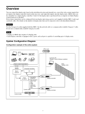
... between display units using a power cord (supplied with the ZRD-2 only) and a network cable. (For details on the number of controlling up to the display controller based on the array size, and output the signals onto the display units. 4K2K video can be controlled via a single display controller. Do not use , convert the video content signals that can be connected, refer to the Installation Manual.) Caution Use the Category 6a cable supplied with 12 ports, and each port is installed. System Configuration Diagram...
... between display units using a power cord (supplied with the ZRD-2 only) and a network cable. (For details on the number of controlling up to the display controller based on the array size, and output the signals onto the display units. 4K2K video can be controlled via a single display controller. Do not use , convert the video content signals that can be connected, refer to the Installation Manual.) Caution Use the Category 6a cable supplied with 12 ports, and each port is installed. System Configuration Diagram...

Operating Instructions
Page 5
... UNIT OUTPUT connector on the display controller. 5 In particular, be aware that connecting these connectors are not Ethernet signals. IN (AC power input) connector Use a power cord (supplied with the ZRD-2 only) or Category 7 cable (not supplied) to connect this connector to the OUT (unit output) connector on the succeeding display unit in the daisy-chain connection. a Unit joints Connect to a hub. For details, see "Troubleshooting" (page 17). The input/output signals for...
... UNIT OUTPUT connector on the display controller. 5 In particular, be aware that connecting these connectors are not Ethernet signals. IN (AC power input) connector Use a power cord (supplied with the ZRD-2 only) or Category 7 cable (not supplied) to connect this connector to the OUT (unit output) connector on the succeeding display unit in the daisy-chain connection. a Unit joints Connect to a hub. For details, see "Troubleshooting" (page 17). The input/output signals for...
Operating Instructions
Page 6
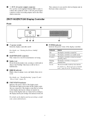
..., and lights when errors occur. For details on (normal operating status). fed c a 1 (power) switch Turns the display controller on the succeeding display unit in standby mode. Indicator Off Lit orange Lit green Blinking green Lit red Status The display controller is not used for the last display unit in the daisy-chain connection. The display controller is used for maintenance servicing. OUT (AC power output) connector Use a power cord (supplied with the ZRD-2 only) to connect this...
..., and lights when errors occur. For details on (normal operating status). fed c a 1 (power) switch Turns the display controller on the succeeding display unit in standby mode. Indicator Off Lit orange Lit green Blinking green Lit red Status The display controller is not used for the last display unit in the daisy-chain connection. The display controller is used for maintenance servicing. OUT (AC power output) connector Use a power cord (supplied with the ZRD-2 only) to connect this...

Operating Instructions
Page 7
... earth conductor, even during operation inspections. Use a Category 7 cable (not supplied) to connect this when using multiple display controllers to the controller PC via a USB (SERIAL) connection. IN (AC power input) connector Use a power cord (not supplied) to connect this to connect to control the display units. Caution Failure to connect the system to the circuit breaker. i 3D SYNC IN connector (mini-DIN, 3-pin) Inputs 3D sync signals. k CTRL (control) connector 1 (RJ-45) Use this connector to the...
... earth conductor, even during operation inspections. Use a Category 7 cable (not supplied) to connect this when using multiple display controllers to the controller PC via a USB (SERIAL) connection. IN (AC power input) connector Use a power cord (not supplied) to connect this to connect to control the display units. Caution Failure to connect the system to the circuit breaker. i 3D SYNC IN connector (mini-DIN, 3-pin) Inputs 3D sync signals. k CTRL (control) connector 1 (RJ-45) Use this connector to the...

Operating Instructions
Page 8
... you are not displayed within 5 minutes of Display Control Software, the display units will turn on all the display controllers by connecting the power cord to the display controller Caution Always connect the display controller's power cord to the configured delay. Caution When inputting 4K-equivalent HDMI signals, use . • Turning the power on via the display controller • Turning the power on via the display controller 1 Press and hold the power switch again. 8 If pictures are not inputting 4K-equivalent HDMI signals. n HDMI (video input) connectors 1 and 2 (ZRCT200...
... you are not displayed within 5 minutes of Display Control Software, the display units will turn on all the display controllers by connecting the power cord to the display controller Caution Always connect the display controller's power cord to the configured delay. Caution When inputting 4K-equivalent HDMI signals, use . • Turning the power on via the display controller • Turning the power on via the display controller 1 Press and hold the power switch again. 8 If pictures are not inputting 4K-equivalent HDMI signals. n HDMI (video input) connectors 1 and 2 (ZRCT200...

Operating Instructions
Page 9
... to start menu to remaining lit green. Turning the Power Off You can enter standby mode by connecting the power cord to the display controller When [Function] - [System Settings] - [Direct Array Power On] is still blinking red. 2 Turn on the video source equipment. You can turn off the system's power using one of two methods. • Turning the power off via the display controller • Turning the power off via Display Control Software Turning the power off via Display Control Software 1 Turn off the video...
... to start menu to remaining lit green. Turning the Power Off You can enter standby mode by connecting the power cord to the display controller When [Function] - [System Settings] - [Direct Array Power On] is still blinking red. 2 Turn on the video source equipment. You can turn off the system's power using one of two methods. • Turning the power off via the display controller • Turning the power off via Display Control Software Turning the power off via Display Control Software 1 Turn off the video...

Operating Instructions
Page 10
... Display Control Software. The video input changes. [HDMI1] (ZRCT-200 only): Use HDMI connector 1 to display pictures. [HDMI2] (ZRCT-200 only): Use HDMI connector 2 to display pictures. [DVI] (ZRCT-100 only): Use the DVI connectors to display pictures as large as "sub controllers"). In addition, the video input settings will not be applied to the sub controllers if they are used.) Example of the display unit to standby mode without disconnecting the video signal transmitter and the display controller...
... Display Control Software. The video input changes. [HDMI1] (ZRCT-200 only): Use HDMI connector 1 to display pictures. [HDMI2] (ZRCT-200 only): Use HDMI connector 2 to display pictures. [DVI] (ZRCT-100 only): Use the DVI connectors to display pictures as large as "sub controllers"). In addition, the video input settings will not be applied to the sub controllers if they are used.) Example of the display unit to standby mode without disconnecting the video signal transmitter and the display controller...
Operating Instructions
Page 11
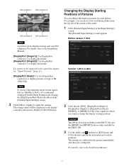
... details on the supported video signals for display, see "Signal Formats" (page 21). [DisplayPort (Dual)]: Use two DisplayPort connectors to display the picture. Note If you are only inputting single-stream signals that are 50p/60p or lower, we recommend clicking [Detailed Input Settings] and clearing the [High Frame Rate Mode] checkbox in the [Input Settings] screen. For example, you want to change the display positions for the ZRCT...
... details on the supported video signals for display, see "Signal Formats" (page 21). [DisplayPort (Dual)]: Use two DisplayPort connectors to display the picture. Note If you are only inputting single-stream signals that are 50p/60p or lower, we recommend clicking [Detailed Input Settings] and clearing the [High Frame Rate Mode] checkbox in the [Input Settings] screen. For example, you want to change the display positions for the ZRCT...
Operating Instructions
Page 12
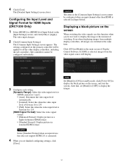
...]. After that does not support HDMI 2.0 is between 0 to 255. [HDMI Signal Format]: Select the video signal format. • [Enhanced Format]: Display pictures in a higher definition HDMI format. • [Standard Format]: Display pictures in standby mode, click [Power ON] to display the images. 12 Caution Select [Standard Format] when an input device that , set [Blank] to [OFF] to display the black picture on the screen, and start the system. Configuring the Input Level and Signal Format for HDMI Inputs (ZRCT-200 Only...
...]. After that does not support HDMI 2.0 is between 0 to 255. [HDMI Signal Format]: Select the video signal format. • [Enhanced Format]: Display pictures in a higher definition HDMI format. • [Standard Format]: Display pictures in standby mode, click [Power ON] to display the images. 12 Caution Select [Standard Format] when an input device that , set [Blank] to [OFF] to display the black picture on the screen, and start the system. Configuring the Input Level and Signal Format for HDMI Inputs (ZRCT-200 Only...
Operating Instructions
Page 13
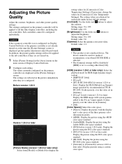
... each mode under factory default settings. [Contrast]: Use the slider and buttons to [Custom10] (version 1.20.0 or later only): Display pictures using a custom color space. 13 Caution If the a primary controller is not configured via Display Control Software or the primary controller is not already turned on the primary controller are identical for [Contrast] to [Color Temperature Settings]. The values currently configured on at the time the [Picture Settings] screen is not a medical device...
... each mode under factory default settings. [Contrast]: Use the slider and buttons to [Custom10] (version 1.20.0 or later only): Display pictures using a custom color space. 13 Caution If the a primary controller is not configured via Display Control Software or the primary controller is not already turned on the primary controller are identical for [Contrast] to [Color Temperature Settings]. The values currently configured on at the time the [Picture Settings] screen is not a medical device...
Operating Instructions
Page 14
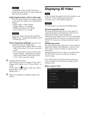
... signals for HDMI signals. 3D frame sequential mode: This mode alternately inputs the two video signals (L signal and R signal) to display the [3D Settings] screen. Internally generated 3D sync signals are output from the display unit. Select [3D Settings] in the [Array] menu on 3D sync signal inputs from the 3D SYNC IN connector are output from the display unit. Caution 3D video display is set to a setting other than [Off] (version 1.20.0 through 1.21.1). [Color Temperature Settings...
... signals for HDMI signals. 3D frame sequential mode: This mode alternately inputs the two video signals (L signal and R signal) to display the [3D Settings] screen. Internally generated 3D sync signals are output from the display unit. Select [3D Settings] in the [Array] menu on 3D sync signal inputs from the 3D SYNC IN connector are output from the display unit. Caution 3D video display is set to a setting other than [Off] (version 1.20.0 through 1.21.1). [Color Temperature Settings...
Operating Instructions
Page 15
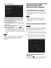
... Settings] screen. Version 1.22.0 or later Synchronizing with Display Control Software or the primary controller is enabled immediately. Inputting External Sync Signals Input the external sync signal to adjust the phase (when 3D video is not displayed properly). It works only if [3D Dual Input Mode] is set. [3D Sync Signal Invert Mode]: Select this checkbox for versions 1.20.0 or later restores the default value. Adjusting the light-up delay time for display units Use...
... Settings] screen. Version 1.22.0 or later Synchronizing with Display Control Software or the primary controller is enabled immediately. Inputting External Sync Signals Input the external sync signal to adjust the phase (when 3D video is not displayed properly). It works only if [3D Dual Input Mode] is set. [3D Sync Signal Invert Mode]: Select this checkbox for versions 1.20.0 or later restores the default value. Adjusting the light-up delay time for display units Use...
Operating Instructions
Page 16
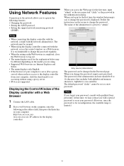
... screen to change the password. The default password "cledis" cannot be changed in for [Administrator] The password can be set as the password in the address field, then press the Enter key on the model you are using. • Supported Web browsers are Internet Explorer and Safari. • The menu displays only English. • If the browser of the administrator is preset to set to [Use a proxy server] when you access...
... screen to change the password. The default password "cledis" cannot be changed in for [Administrator] The password can be set as the password in the address field, then press the Enter key on the model you are using. • Supported Web browsers are Internet Explorer and Safari. • The menu displays only English. • If the browser of the administrator is preset to set to [Use a proxy server] when you access...
Operating Instructions
Page 17
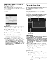
ADCP Service setting area Troubleshooting Be sure to enabled or disabled. If the problem persists, contact your local Sony representative. The factory default setting is allowed to receive. If an error or warning occurs, see "Error Codes" (page 19), and resolve the problem as soon as possible. The password is the same as that the ADCP server is "60." -Host Address: Input the IP address that of the Web page...
ADCP Service setting area Troubleshooting Be sure to enabled or disabled. If the problem persists, contact your local Sony representative. The factory default setting is allowed to receive. If an error or warning occurs, see "Error Codes" (page 19), and resolve the problem as soon as possible. The password is the same as that the ADCP server is "60." -Host Address: Input the IP address that of the Web page...

Operating Instructions
Page 18
.... To reestablish connection Close the dialog box. 18 After the POWER indicator blinks red/orange, the normal standby mode is suspended. The display units will also enter the normal standby mode. The forced standby mode is entered, and the POWER indicator lights red. 2 Press and hold the power switch on the display controller for about 2 seconds. Select [Disconnect] in the [System] menu on a display unit by...
.... To reestablish connection Close the dialog box. 18 After the POWER indicator blinks red/orange, the normal standby mode is suspended. The display units will also enter the normal standby mode. The forced standby mode is entered, and the POWER indicator lights red. 2 Press and hold the power switch on the display controller for about 2 seconds. Select [Disconnect] in the [System] menu on a display unit by...
Operating Instructions
Page 19
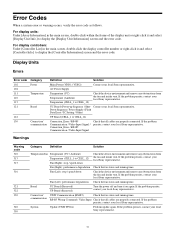
...) Perform update again. If the problem persists, contact your local Sony representative. Contact your local Sony representative. Down Sequence / Power Supply / Flash Data Error / IC Setting / Other) UP Board (CELL_1 to CELL_12) Fan (Right): stop / speed-down Check the device environment and remove any obstructions from the fan and intake vent. Error Codes When a system error or warning occurs, verify the error code as follows. AC Power Supply Temperature...
...) Perform update again. If the problem persists, contact your local Sony representative. Contact your local Sony representative. Down Sequence / Power Supply / Flash Data Error / IC Setting / Other) UP Board (CELL_1 to CELL_12) Fan (Right): stop / speed-down Check the device environment and remove any obstructions from the fan and intake vent. Error Codes When a system error or warning occurs, verify the error code as follows. AC Power Supply Temperature...
Operating Instructions
Page 20
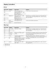
... obstructing the fan. Controller configuration data mismatch warning DIF signal connection warning 1) / VIF signal connection warning 2) / Link connection warning / Sync connection warning Update warning (CPU / DIF 1) / VIF 2) / PIF) Check the installation, wiring, and Display Control Software settings, and if a problem does not exist, turn the power off and turn it on again. If the problem persists, contact your local Sony representative. If the problem persists, contact your local Sony representative. Display Controllers Errors Error code 001 002 Category...
... obstructing the fan. Controller configuration data mismatch warning DIF signal connection warning 1) / VIF signal connection warning 2) / Link connection warning / Sync connection warning Update warning (CPU / DIF 1) / VIF 2) / PIF) Check the installation, wiring, and Display Control Software settings, and if a problem does not exist, turn the power off and turn it on again. If the problem persists, contact your local Sony representative. If the problem persists, contact your local Sony representative. Display Controllers Errors Error code 001 002 Category...

Operating Instructions
Page 22
... × 1080 Input frame rate 1) Input bit length 60p/50p 8-bit Input color sampling RGB 4:4:4 1) 1,000/1,001 frame rate is also supported for 60p/30p/24p. 10) Use a Premium High Speed HDMI cable when using this input signal. 11) Converted to YCbCr 4:2:2, 10-/12-bit first, and then converted to RGB 4:4:4, 10-bit for 120p/60p/30p/24p. 2) Input 1920 × 2160 signals (multi-stream...
... × 1080 Input frame rate 1) Input bit length 60p/50p 8-bit Input color sampling RGB 4:4:4 1) 1,000/1,001 frame rate is also supported for 60p/30p/24p. 10) Use a Premium High Speed HDMI cable when using this input signal. 11) Converted to YCbCr 4:2:2, 10-/12-bit first, and then converted to RGB 4:4:4, 10-bit for 120p/60p/30p/24p. 2) Input 1920 × 2160 signals (multi-stream...


