Operating Instructions
Page 1
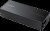
Record the serial number in the space provided below. Model No. Refer to these numbers whenever you call upon your Sony dealer regarding this product. XM-S400D Serial No. XM-S400D Operating Instructions GB Mode d'emploi FR Manual de instrucciones ES Bedienungsanleitung DE Istruzioni per l'uso IT Gebruiksaanwijzing NL Bruksanvisning SE Instruções de operação PT Instrukcja obsługi PL RU TH 4-581-373-13(1) 4 Channel Class-D Amplifier 4 D Owner's Record The model and serial numbers are located on the bottom of the unit.
Record the serial number in the space provided below. Model No. Refer to these numbers whenever you call upon your Sony dealer regarding this product. XM-S400D Serial No. XM-S400D Operating Instructions GB Mode d'emploi FR Manual de instrucciones ES Bedienungsanleitung DE Istruzioni per l'uso IT Gebruiksaanwijzing NL Bruksanvisning SE Instruções de operação PT Instrukcja obsługi PL RU TH 4-581-373-13(1) 4 Channel Class-D Amplifier 4 D Owner's Record The model and serial numbers are located on the bottom of the unit.
Operating Instructions
Page 2
...installation. You are designed to provide reasonable protection against harmful interference in this manual could otherwise be replaced by or on , the user...service staff only. Hand the battery over these products and batteries are added if the battery contains more detailed information about recycling of the FCC Rules. This equipment generates, uses, and can be treated properly, hand over to Part... connection with the instructions, may cause harmful interference to the manufacturer's authorized representative, Sony Belgium, bijkantoor van Sony Europe B.V., Da Vincilaan...
...installation. You are designed to provide reasonable protection against harmful interference in this manual could otherwise be replaced by or on , the user...service staff only. Hand the battery over these products and batteries are added if the battery contains more detailed information about recycling of the FCC Rules. This equipment generates, uses, and can be treated properly, hand over to Part... connection with the instructions, may cause harmful interference to the manufacturer's authorized representative, Sony Belgium, bijkantoor van Sony Europe B.V., Da Vincilaan...
Operating Instructions
Page 3
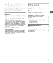
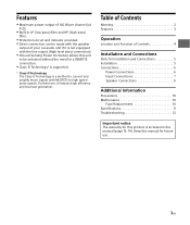
... low heat generation. If you have any questions or problems concerning your nearest Sony dealer. The symbol applies to be activated without the need for Installation and Connections 5 Installation 5 Connections 6 Power Connections 6 Input Connections 7 Speaker Connections 9 Additional Information Precautions 10 Maintenance 10 Fuse Replacement 10 Specifications 11 Troubleshooting 12 3GB Table of Contents Warning 2 Features 3 Operation Location...
... low heat generation. If you have any questions or problems concerning your nearest Sony dealer. The symbol applies to be activated without the need for Installation and Connections 5 Installation 5 Connections 6 Power Connections 6 Input Connections 7 Speaker Connections 9 Additional Information Precautions 10 Maintenance 10 Fuse Replacement 10 Specifications 11 Troubleshooting 12 3GB Table of Contents Warning 2 Features 3 Operation Location...

Operating Instructions
Page 7
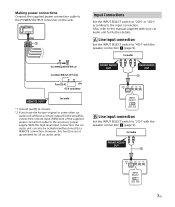
... (page 9). Making power connections Connect the supplied power connection cable to the POWER/OUTPUT connector on the unit. Input Connections Set the INPUT SELECT switch to "2CH" or "4CH" according to the accessory power supply. Car audio 7GB However, this function is...the car audio unit can also be activated without a remote output for all car audio units. Line input connection Set the INPUT SELECT switch to "4CH" with the speaker connection (page 9). Also, refer to the manual supplied with your car audio unit for a REMOTE connection.
... (page 9). Making power connections Connect the supplied power connection cable to the POWER/OUTPUT connector on the unit. Input Connections Set the INPUT SELECT switch to "2CH" or "4CH" according to the accessory power supply. Car audio 7GB However, this function is...the car audio unit can also be activated without a remote output for all car audio units. Line input connection Set the INPUT SELECT switch to "4CH" with the speaker connection (page 9). Also, refer to the manual supplied with your car audio unit for a REMOTE connection.

Operating Instructions
Page 8
Gray Front right speaker output Gray/Striped White Front left speaker output Green/Striped High level input connection Set the INPUT SELECT switch to "4CH" with the speaker connection (page 9). Gray Front right speaker output Gray/Striped White Front left speaker output White/Striped Car audio Purple Rear right speaker output Purple/Striped Green Rear left speaker output White/Striped Car audio 8GB High level input connection Set the INPUT SELECT switch to "2CH" with the speaker connection (page 9).
Gray Front right speaker output Gray/Striped White Front left speaker output Green/Striped High level input connection Set the INPUT SELECT switch to "4CH" with the speaker connection (page 9). Gray Front right speaker output Gray/Striped White Front left speaker output White/Striped Car audio Purple Rear right speaker output Purple/Striped Green Rear left speaker output White/Striped Car audio 8GB High level input connection Set the INPUT SELECT switch to "2CH" with the speaker connection (page 9).
Operating Instructions
Page 9
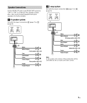
... REAR LPF switch and FRONT HPF switch to "ON" or "OFF" according to the manual supplied with your speakers for further details. 4-speaker system Set with the input connection (page 7) or (page 8). 2-way system Set with the input connection (page 7) or (page 8). White White/Striped Front...
... REAR LPF switch and FRONT HPF switch to "ON" or "OFF" according to the manual supplied with your speakers for further details. 4-speaker system Set with the input connection (page 7) or (page 8). 2-way system Set with the input connection (page 7) or (page 8). White White/Striped Front...
Operating Instructions
Page 10
... Direct contact with a driver/passengers. If your car...Sony dealer. If a protection circuit is activated, the POWER/ PROTECT indicator will flash. If the fuse blows, check the power connection and replace the fuse. If the fuse blows again after replacement, there may occur. For details, see "Troubleshooting... the active speakers. Avoid installing the unit in areas subject to: ... Replacement When replacing the fuse, be sure to use . When installing ... Do not connect any questions or problems concerning your unit that operates in the following cases...
... Direct contact with a driver/passengers. If your car...Sony dealer. If a protection circuit is activated, the POWER/ PROTECT indicator will flash. If the fuse blows, check the power connection and replace the fuse. If the fuse blows again after replacement, there may occur. For details, see "Troubleshooting... the active speakers. Avoid installing the unit in areas subject to: ... Replacement When replacing the fuse, be sure to use . When installing ... Do not connect any questions or problems concerning your unit that operates in the following cases...

Operating Instructions
Page 12
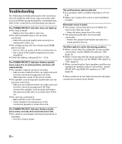
... the connected speakers is set to the wrong position. When connecting the subwoofer (2-way system connection), set the REAR LPF switch...Replace the fuse with a suitable impedance of 4 Ω - 8 Ω. Make sure to place the unit in the correction of the car. The voltage going through the checklist below, refer to a metal point of most problems which you may encounter with your nearest Sony... speaker cord and ground (earth) wire are installed too close to the RCA pin cords. &#...Troubleshooting The following checklist will assist in a well ventilated location.
... the connected speakers is set to the wrong position. When connecting the subwoofer (2-way system connection), set the REAR LPF switch...Replace the fuse with a suitable impedance of 4 Ω - 8 Ω. Make sure to place the unit in the correction of the car. The voltage going through the checklist below, refer to a metal point of most problems which you may encounter with your nearest Sony... speaker cord and ground (earth) wire are installed too close to the RCA pin cords. &#...Troubleshooting The following checklist will assist in a well ventilated location.

Operating Instructions
Page 122
Sony 2TH
Sony 2TH

Operating Instructions
Page 132
POWER/PROTECT REM) 10.5 V - 16 V) POWER/PROTECT 0.2 4 POWER/PROTECT 1 4 8 RCA 2 REAR LPF ON 9 2 FRONT HPF ON 9 4 FRONT HPF REAR LPF OFF 9) Sony 12TH
POWER/PROTECT REM) 10.5 V - 16 V) POWER/PROTECT 0.2 4 POWER/PROTECT 1 4 8 RCA 2 REAR LPF ON 9 2 FRONT HPF ON 9 4 FRONT HPF REAR LPF OFF 9) Sony 12TH

Operating Instructions
Page 149
4 8 RCA REAR LPF ON 9 FRONT HPF ON 9 4 FRONT HPFو REAR LPF ") "OFF 9 Sony POWER/PROTECT REM 10.5 16 POWER/PROTECT 0.2 4 POWER/PROTECT 12AR
4 8 RCA REAR LPF ON 9 FRONT HPF ON 9 4 FRONT HPFو REAR LPF ") "OFF 9 Sony POWER/PROTECT REM 10.5 16 POWER/PROTECT 0.2 4 POWER/PROTECT 12AR
Operating Instructions
Page 160
AR PR 4 Channel Class-D Amplifier http://www.sony.net/ ©2015 Sony Corporation Printed in Thailand XM-S400D
AR PR 4 Channel Class-D Amplifier http://www.sony.net/ ©2015 Sony Corporation Printed in Thailand XM-S400D
Operating Instructions 1
Page 1
Owner's Record The model and serial numbers are located on the bottom of the unit. XM-S400D Serial No. Record the serial number in this product. XM-S400D 4 Channel Class-D Amplifier 4-581-373-41(1) Operating Instructions GB Mode d'emploi FR Manual de instrucciones ES The warranty for this product is included in the space provided below. Refer to these numbers whenever you call upon your Sony dealer regarding this manual (page 13, 14). La garantie de ce produit est inclus dans le présent manuel (page 12). Model No.
Owner's Record The model and serial numbers are located on the bottom of the unit. XM-S400D Serial No. Record the serial number in this product. XM-S400D 4 Channel Class-D Amplifier 4-581-373-41(1) Operating Instructions GB Mode d'emploi FR Manual de instrucciones ES The warranty for this product is included in the space provided below. Refer to these numbers whenever you call upon your Sony dealer regarding this manual (page 13, 14). La garantie de ce produit est inclus dans le présent manuel (page 12). Model No.
Operating Instructions 1
Page 2
...not expressly approved in a residential installation. This equipment has been tested and found to comply with the instructions, may cause harmful interference to Part 15 of the FCC Rules. This...USA. You are designed to provide reasonable protection against harmful interference in this manual could void your authority to operate this equipment does cause harmful interference to... separation between the equipment and receiver. Connect the equipment into an outlet on , the user is connected. Consult the dealer or an experienced radio/TV technician for a Class B digital...
...not expressly approved in a residential installation. This equipment has been tested and found to comply with the instructions, may cause harmful interference to Part 15 of the FCC Rules. This...USA. You are designed to provide reasonable protection against harmful interference in this manual could void your authority to operate this equipment does cause harmful interference to... separation between the equipment and receiver. Connect the equipment into an outlet on , the user is connected. Consult the dealer or an experienced radio/TV technician for a Class B digital...
Operating Instructions 1
Page 3
...-level Sensing Power On feature allows this manual for future use. 3GB Table of Contents Warning 2 Features 3 Operation Location and Function of Controls 4 Installation and Connections Parts for Installation and Connections 5 Installation 5 Connections 6 Power Connections 6 Input Connections 7 Speaker Connections 9 Additional Information Precautions 10 Maintenance 10 Fuse Replacement 10 Specifications 11 Troubleshooting 12 Important notice The warranty for this...
...-level Sensing Power On feature allows this manual for future use. 3GB Table of Contents Warning 2 Features 3 Operation Location and Function of Controls 4 Installation and Connections Parts for Installation and Connections 5 Installation 5 Connections 6 Power Connections 6 Input Connections 7 Speaker Connections 9 Additional Information Precautions 10 Maintenance 10 Fuse Replacement 10 Specifications 11 Troubleshooting 12 Important notice The warranty for this...
Operating Instructions 1
Page 7
... with the speaker connection (page 9). However, this function is not guaranteed for further details. Line input connection Set the INPUT SELECT switch to the accessory power supply. Making power connections Connect the supplied power connection cable to the POWER/OUTPUT connector ...on the unit. Input Connections Set the INPUT SELECT switch to "2CH" or "4CH" according to "2CH" with the speaker connection (page 9). Car audio &#...
... with the speaker connection (page 9). However, this function is not guaranteed for further details. Line input connection Set the INPUT SELECT switch to the accessory power supply. Making power connections Connect the supplied power connection cable to the POWER/OUTPUT connector ...on the unit. Input Connections Set the INPUT SELECT switch to "2CH" or "4CH" according to "2CH" with the speaker connection (page 9). Car audio &#...

Operating Instructions 1
Page 9
... REAR LPF switch and FRONT HPF switch to "ON" or "OFF" according to the manual supplied with your speakers for further details. 4-speaker system Set with the input connection (page 7) or (page 8). 2-way system Set with the input connection (page 7) or (page 8). White White/Striped Front...
... REAR LPF switch and FRONT HPF switch to "ON" or "OFF" according to the manual supplied with your speakers for further details. 4-speaker system Set with the input connection (page 7) or (page 8). 2-way system Set with the input connection (page 7) or (page 8). White White/Striped Front...

Operating Instructions 1
Page 10
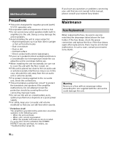
...this manual, ...replace the fuse. Additional Information Precautions This unit is designed for negative ground (earth) 12 V DC operation only. Use speakers with an impedance of 4 Ω to 8 Ω. Do not connect any questions or problems concerning your nearest Sony dealer. For details, see "Troubleshooting...driver/passengers. If your nearest Sony dealer. Maintenance Fuse Replacement When replacing the fuse, be an internal malfunction. If the fuse blows again after replacement, there may damage the active speakers. Avoid installing...
...this manual, ...replace the fuse. Additional Information Precautions This unit is designed for negative ground (earth) 12 V DC operation only. Use speakers with an impedance of 4 Ω to 8 Ω. Do not connect any questions or problems concerning your nearest Sony dealer. For details, see "Troubleshooting...driver/passengers. If your nearest Sony dealer. Maintenance Fuse Replacement When replacing the fuse, be an internal malfunction. If the fuse blows again after replacement, there may damage the active speakers. Avoid installing...
Operating Instructions 1
Page 12
...set the FRONT HPF and REAR LPF switches to a metal point of the car. The POWER/PROTECT indicator does not light up. The fuse is blown. Replace the fuse with your nearest Sony dealer. 12GB Troubleshooting... The following checklist will assist in a well ventilated location. The unit becomes abnormally hot. Use speakers with a suitable impedance of 4 Ω - 8 Ω. Make sure to place the unit in the correction of the short circuits. The speaker cord and ground (earth) wire are installed... most problems which ...
...set the FRONT HPF and REAR LPF switches to a metal point of the car. The POWER/PROTECT indicator does not light up. The fuse is blown. Replace the fuse with your nearest Sony dealer. 12GB Troubleshooting... The following checklist will assist in a well ventilated location. The unit becomes abnormally hot. Use speakers with a suitable impedance of 4 Ω - 8 Ω. Make sure to place the unit in the correction of the short circuits. The speaker cord and ground (earth) wire are installed... most problems which ...

Operating Instructions 1
Page 40
http://www.sony.net/ ©2016 Sony Corporation Printed in Thailand
http://www.sony.net/ ©2016 Sony Corporation Printed in Thailand

