Operating Instructions
Page 1
UWP-V1/V2/V6 UWP-X7/X8 © 2008 Sony Corporation 3-870-286-13 (1) Wireless Microphone Package Operating Instructions Before operating the unit, please read this manual thoroughly and retain it for future reference.
UWP-V1/V2/V6 UWP-X7/X8 © 2008 Sony Corporation 3-870-286-13 (1) Wireless Microphone Package Operating Instructions Before operating the unit, please read this manual thoroughly and retain it for future reference.
Operating Instructions
Page 2
... described in their Radio Standard Specification RSS-123. Use of Sony wireless devices is issued on no change to operate this device. Notice for uncontrolled equipment and meets the FCC radio frequency (RF) Exposure Guidelines in the U.S.A. Operation is regulated by the Federal ...operate this product. Model No Serial No WARNING Batteries shall not be contacted. IMPORTANT NOTE: To comply with the FCC RF exposure compliance requirements, no -interference, noprotection basis with FCC radiation exposure limits set forth for customers in Canada: Use of Sony wireless...
... described in their Radio Standard Specification RSS-123. Use of Sony wireless devices is issued on no change to operate this device. Notice for uncontrolled equipment and meets the FCC radio frequency (RF) Exposure Guidelines in the U.S.A. Operation is regulated by the Federal ...operate this product. Model No Serial No WARNING Batteries shall not be contacted. IMPORTANT NOTE: To comply with the FCC RF exposure compliance requirements, no -interference, noprotection basis with FCC radiation exposure limits set forth for customers in Canada: Use of Sony wireless...
Operating Instructions
Page 14
... changes or modifications not expressly approved in this manual could void your Sony dealer regarding this product. If you have any interference received, including interference that may cause harmful interference to radio communications. However, there is connected. - WARNING Batteries shall not be shielded in order to comply with the instructions, may cause undesired operation. Reorient or relocate the receiving...
... changes or modifications not expressly approved in this manual could void your Sony dealer regarding this product. If you have any interference received, including interference that may cause harmful interference to radio communications. However, there is connected. - WARNING Batteries shall not be shielded in order to comply with the instructions, may cause undesired operation. Reorient or relocate the receiving...
Operating Instructions
Page 19
... indication 46 Transmitter Settings 47 Setting the transmission channel 47 Setting the RF output power level 48 Setting the attenuation level of the audio input 49 Resetting the accumulated use time indication 49 System Configurations 50 Configuration examples of the UWP-V1/V2/X7/X8 50 Configuration example of the UWP-V6 53 Error Messages 54 Troubleshooting 55 Important...
... indication 46 Transmitter Settings 47 Setting the transmission channel 47 Setting the RF output power level 48 Setting the attenuation level of the audio input 49 Resetting the accumulated use time indication 49 System Configurations 50 Configuration examples of the UWP-V1/V2/X7/X8 50 Configuration example of the UWP-V6 53 Error Messages 54 Troubleshooting 55 Important...
Operating Instructions
Page 21
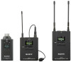
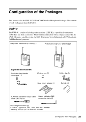
...-P2), and their accessories. When used in conjunction with a compact camcorder, the UWP-V1 makes a mobile system for the UWP-V1/V2/V6/X7/X8 Wireless Microphone Packages. Configuration of the Packages This manual is for ENG (Electronic News Gathering...-directional lavalier microphone (1) Wind screen (3) Holder clip (1) Shoe mount adapter (1) Belt clip (2) XLR-BMP conversion output cable Stereo mini plug-BMP for the URX-P2 (1) conversion cable (1) Operating Instructions (1) CD-ROM (1) (for U30, U42, CE62, and CE67 models) Warranty card (1) (for U30 and U42 models) 21 Configuration...
...-P2), and their accessories. When used in conjunction with a compact camcorder, the UWP-V1 makes a mobile system for the UWP-V1/V2/V6/X7/X8 Wireless Microphone Packages. Configuration of the Packages This manual is for ENG (Electronic News Gathering...-directional lavalier microphone (1) Wind screen (3) Holder clip (1) Shoe mount adapter (1) Belt clip (2) XLR-BMP conversion output cable Stereo mini plug-BMP for the URX-P2 (1) conversion cable (1) Operating Instructions (1) CD-ROM (1) (for U30, U42, CE62, and CE67 models) Warranty card (1) (for U30 and U42 models) 21 Configuration...
Operating Instructions
Page 22
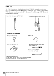
... a mobile system for U30 and U42 models) 22 Configuration of a hand-held microphone (UTX-H2) (1) Portable diversity tuner (URX-P2) (1) Supplied accessories Microphone holder (1) Belt clip (1) Shoe mount adapter (1) XLR-BMP conversion output cable for the URX-P2 (1) Stereo mini plug-BMP conversion cable (1) Operating Instructions (1) CD-ROM (1) (for U30, U42, CE62, and CE67 models) Warranty card (1) (for ENG (Electronic News...
... a mobile system for U30 and U42 models) 22 Configuration of a hand-held microphone (UTX-H2) (1) Portable diversity tuner (URX-P2) (1) Supplied accessories Microphone holder (1) Belt clip (1) Shoe mount adapter (1) XLR-BMP conversion output cable for the URX-P2 (1) Stereo mini plug-BMP conversion cable (1) Operating Instructions (1) CD-ROM (1) (for U30, U42, CE62, and CE67 models) Warranty card (1) (for ENG (Electronic News...

Operating Instructions
Page 25
UWP-X8 The UWP-X8 consists of a hand-held microphone (UTX-H2) (1) Diversity tuner module (URX-M2) (1) Supplied accessories Microphone holder (1) Operating Instructions (1) CD-ROM (1) (for U30, U42, CE62, and CE67 models) Warranty card (1) (for U30 and U42 models) 25 Configuration of use and required system scale becomes possible. By installing the tuner module into the tuner base unit or the powered mixer, the system construction to meet the desired purpose of the Packages Hand-held microphone (UTX-H2), a diversity tuner module (URX-M2), and their accessories.
UWP-X8 The UWP-X8 consists of a hand-held microphone (UTX-H2) (1) Diversity tuner module (URX-M2) (1) Supplied accessories Microphone holder (1) Operating Instructions (1) CD-ROM (1) (for U30, U42, CE62, and CE67 models) Warranty card (1) (for U30 and U42 models) 25 Configuration of use and required system scale becomes possible. By installing the tuner module into the tuner base unit or the powered mixer, the system construction to meet the desired purpose of the Packages Hand-held microphone (UTX-H2), a diversity tuner module (URX-M2), and their accessories.

Operating Instructions
Page 26
...on transmitter (UTX-P1) This is equipped with easy operation. The RF power output can be set at 5 mW. The Clear Channel Scan function is also provided to search available channels with a built-in antenna and a unidirectional dynamic microphone unit. Portable diversity tuner (URXP2) This tuner employs...wireless microphone packages (referred to as a PA (public address) system. The RF power output can be set at 30 mW or at 50 mW. 26 Features It comes with an adapter for mounting the tuner on transmitter (UTX-P1) is provided for the UWP-V6 only.) The UWP series packages can be used...
...on transmitter (UTX-P1) This is equipped with easy operation. The RF power output can be set at 5 mW. The Clear Channel Scan function is also provided to search available channels with a built-in antenna and a unidirectional dynamic microphone unit. Portable diversity tuner (URXP2) This tuner employs...wireless microphone packages (referred to as a PA (public address) system. The RF power output can be set at 30 mW or at 50 mW. 26 Features It comes with an adapter for mounting the tuner on transmitter (UTX-P1) is provided for the UWP-V6 only.) The UWP series packages can be used...

Operating Instructions
Page 28
... Accommodates two LR6 (size AA) alkaline batteries. 28 Parts Identification For this connector. If the sound is used . Parts Identification Body-pack transmitter (UTX-B2) a Antenna b MIC/LINE (microphone/line) input selector Set according to the equipment connected to the audio input level as follows. c Audio input connector Connect the supplied lavalier microphone here. d AF/PEAK (audio frequency/peak level) indicator Turns on or...
... Accommodates two LR6 (size AA) alkaline batteries. 28 Parts Identification For this connector. If the sound is used . Parts Identification Body-pack transmitter (UTX-B2) a Antenna b MIC/LINE (microphone/line) input selector Set according to the equipment connected to the audio input level as follows. c Audio input connector Connect the supplied lavalier microphone here. d AF/PEAK (audio frequency/peak level) indicator Turns on or...

Operating Instructions
Page 29
... "-" button resets the accumulated use time The channel/frequency indications for U30 model is stronger than the reference level. Each time you press the SET button in transmission mode, the channel indication changes as follows. Accumulated use time to "00:00". For details on how to insert the batteries, see "Setting the RF output power level" on page 48...
... "-" button resets the accumulated use time The channel/frequency indications for U30 model is stronger than the reference level. Each time you press the SET button in transmission mode, the channel indication changes as follows. Accumulated use time to "00:00". For details on how to insert the batteries, see "Setting the RF output power level" on page 48...

Operating Instructions
Page 30
... U30 model are shown. Transmission channel Transmission frequency Attenuation level of the microphone ON or OFF. The "-" button resets the accumulated use time The channel/frequency indications for U30 model is stronger than the reference level. For details, see "Transmitter Settings" on page 48. For details on how to change and enter display parameters. For details, see "Power Supply...
... U30 model are shown. Transmission channel Transmission frequency Attenuation level of the microphone ON or OFF. The "-" button resets the accumulated use time The channel/frequency indications for U30 model is stronger than the reference level. For details, see "Transmitter Settings" on page 48. For details on how to change and enter display parameters. For details, see "Power Supply...

Operating Instructions
Page 32
... this connector. 32 Parts Identification C BATT (battery) indication Shows the battery condition. g POWER switch Turns the power of the input signal Press the SET button. The "-" button resets the accumulated use time The channel/frequency indications for U30 model are shown. a Antennas b MONITOR connector (3.5-mm diameter stereo mini jack) To monitor the tuner output, connect the headphones to change and enter display...
... this connector. 32 Parts Identification C BATT (battery) indication Shows the battery condition. g POWER switch Turns the power of the input signal Press the SET button. The "-" button resets the accumulated use time The channel/frequency indications for U30 model are shown. a Antennas b MONITOR connector (3.5-mm diameter stereo mini jack) To monitor the tuner output, connect the headphones to change and enter display...

Operating Instructions
Page 33
... insert the batteries, see "Tuner Settings" on page 35. f + (+ selection) / - (- For details, see "Power Supply" on page 43. A RF (radio frequency) indications The number of the RF input signal. The "-" button resets the accumulated use time The channel/frequency indications for U30 model is less than the reference level. g SET button Press to "00:00". B AF (audio frequency) indication Appears...
... insert the batteries, see "Tuner Settings" on page 35. f + (+ selection) / - (- For details, see "Power Supply" on page 43. A RF (radio frequency) indications The number of the RF input signal. The "-" button resets the accumulated use time The channel/frequency indications for U30 model is less than the reference level. g SET button Press to "00:00". B AF (audio frequency) indication Appears...

Operating Instructions
Page 34
... indication (C) for U30 model are shown. Reception channel group and number Reception frequency Press the SET button. Each time you press the SET button, the channel indication changes as follows. d + (+ selection) / - (- Off: RF input is a stereo mini jack, connect the straight (BMP) plug to the tuner and the L-shaped (stereo mini) plug to the microphone input on page 43...
... indication (C) for U30 model are shown. Reception channel group and number Reception frequency Press the SET button. Each time you press the SET button, the channel indication changes as follows. d + (+ selection) / - (- Off: RF input is a stereo mini jack, connect the straight (BMP) plug to the tuner and the L-shaped (stereo mini) plug to the microphone input on page 43...

Operating Instructions
Page 38
... slack out of the microphone cable Run the cable through the clamping part of the transmitter. 38 Attachment and Installation Procedures To attach the holder clip to the microphone To attach the belt clip Push the holder clip against the bottom of the microphone until the holder clip clicks into the hole at the bottom of the windscreen. To attach the wind...
... slack out of the microphone cable Run the cable through the clamping part of the transmitter. 38 Attachment and Installation Procedures To attach the holder clip to the microphone To attach the belt clip Push the holder clip against the bottom of the microphone until the holder clip clicks into the hole at the bottom of the windscreen. To attach the wind...

Operating Instructions
Page 39
...Attachment and Installation Procedures Inserting the plug-on transmitter (UTX-P1) To attach a microphone or a cable Microphone or cable connector Insert the bottom part of the UTX-P1 until it clicks into place. To detach a microphone or a cable Microphone or cable connector ...microphone or cable slowly. Attaching the supplied accessory to the hand-held microphone (UTX-H2) To attach the microphone holder Attaching the optional accessory to the plug-on transmitter (UTX-P1) into the supplied soft case Push the microphone or cable connector (XLR-3-12C connector) against the audio...
...Attachment and Installation Procedures Inserting the plug-on transmitter (UTX-P1) To attach a microphone or a cable Microphone or cable connector Insert the bottom part of the UTX-P1 until it clicks into place. To detach a microphone or a cable Microphone or cable connector ...microphone or cable slowly. Attaching the supplied accessory to the hand-held microphone (UTX-H2) To attach the microphone holder Attaching the optional accessory to the plug-on transmitter (UTX-P1) into the supplied soft case Push the microphone or cable connector (XLR-3-12C connector) against the audio...
Operating Instructions
Page 43
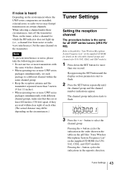
... channels (for U30, U42, CE62, and CE67 models). 1 Press down the SET button for which the RF indicator does not light up (i.e., a channel free from noise or radio wave interference). Refer to the pdf files "Sony Wireless Microphone System Frequency List" on the supplied CD-ROM for U30,... precautions. • Do not use two or more transmitters with the same wireless channels. • When operating two or more UWP series packages simultaneously, set each other. (The actual distance may differ depending on the circumstances.) Tuner Settings Setting the reception channel The procedure below...
... channels (for U30, U42, CE62, and CE67 models). 1 Press down the SET button for which the RF indicator does not light up (i.e., a channel free from noise or radio wave interference). Refer to the pdf files "Sony Wireless Microphone System Frequency List" on the supplied CD-ROM for U30,... precautions. • Do not use two or more transmitters with the same wireless channels. • When operating two or more UWP series packages simultaneously, set each other. (The actual distance may differ depending on the circumstances.) Tuner Settings Setting the reception channel The procedure below...

Operating Instructions
Page 49
...following while there is no signal transmission. Set the POWER switch to OFF to complete the setting, or press the SET button to set other items. The results are stored in memory. The attenuation level can be reset. Note When the MIC/LINE input selector of the UTX-B2 ...use time indication The procedure below is always 0 dB and cannot be set during signal transmission. The change becomes effective the next time you turn on the audio source device. 1 Do the following while there is the same for all UWP series transmitters (UTX-B2/H2/P1). 1 Turn on page 46. 3 Set the POWER...
...following while there is no signal transmission. Set the POWER switch to OFF to complete the setting, or press the SET button to set other items. The results are stored in memory. The attenuation level can be reset. Note When the MIC/LINE input selector of the UTX-B2 ...use time indication The procedure below is always 0 dB and cannot be set during signal transmission. The change becomes effective the next time you turn on the audio source device. 1 Do the following while there is the same for all UWP series transmitters (UTX-B2/H2/P1). 1 Turn on page 46. 3 Set the POWER...

Operating Instructions
Page 50
Upon selecting the devices to be used with the belt clip and the shoe mount adapter attached) Or Hand-held microphone (UTX-H2) Body-pack transmitter (UTX-B2) XDCAM EX/HDV camcorder (PMW-EX1, HVR-Z7, etc.) 1 XLR-BMP conversion output cable for the URX-P2 50 System Configurations ...System Configurations Note Production of the UWP-V1/V2/X7/X8 Sample configuration for ENG (Electronic News Gathering) or EFP (Electronic Field Production) with a camcorder Portable diversity tuner (URX-P2) (with this product, consult your nearest Sony ...
Upon selecting the devices to be used with the belt clip and the shoe mount adapter attached) Or Hand-held microphone (UTX-H2) Body-pack transmitter (UTX-B2) XDCAM EX/HDV camcorder (PMW-EX1, HVR-Z7, etc.) 1 XLR-BMP conversion output cable for the URX-P2 50 System Configurations ...System Configurations Note Production of the UWP-V1/V2/X7/X8 Sample configuration for ENG (Electronic News Gathering) or EFP (Electronic Field Production) with a camcorder Portable diversity tuner (URX-P2) (with this product, consult your nearest Sony ...
Operating Instructions
Page 53
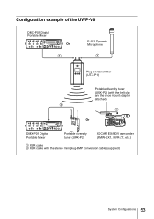
Configuration example of the UWP-V6 DMX-P01 Digital Portable Mixer Or F-112 Dynamic Microphone Plug-on transmitter (UTX-P1) Portable diversity tuner (URX-P2) (with the belt clip and the shoe mount adapter attached) Or DMX-P01 Digital Portable Mixer Portable diversity tuner (URX-P2) XDCAM EX/HDV camcorder (PMW-EX1, HVR-Z7, etc.) 1 XLR cable 2 XLR cable with the stereo mini plug-BMP conversion cable (supplied) 53 System Configurations
Configuration example of the UWP-V6 DMX-P01 Digital Portable Mixer Or F-112 Dynamic Microphone Plug-on transmitter (UTX-P1) Portable diversity tuner (URX-P2) (with the belt clip and the shoe mount adapter attached) Or DMX-P01 Digital Portable Mixer Portable diversity tuner (URX-P2) XDCAM EX/HDV camcorder (PMW-EX1, HVR-Z7, etc.) 1 XLR cable 2 XLR cable with the stereo mini plug-BMP conversion cable (supplied) 53 System Configurations


