
Primary User Manual
Page 3
... Connecting video equipment 9 Adjusting the digital dynamics controller 40 Connecting power amplifiers 11 Adjusting the digital parametric equalizer 41 Connecting the remote control system 12 Storing your private setting 43 Connecting power cords 13 Storing your personal tastes. . • ',de., 14... .• , 11. Introduction Chapter 3 Advanced Operation Overview 4 What is divided into the remote commander 6 Adjusting the sub parameters 37 Choosing a good location 6 (Early reflection time, Early reflection level, Hooking up the sound...
... Connecting video equipment 9 Adjusting the digital dynamics controller 40 Connecting power amplifiers 11 Adjusting the digital parametric equalizer 41 Connecting the remote control system 12 Storing your private setting 43 Connecting power cords 13 Storing your personal tastes. . • ',de., 14... .• , 11. Introduction Chapter 3 Advanced Operation Overview 4 What is divided into the remote commander 6 Adjusting the sub parameters 37 Choosing a good location 6 (Early reflection time, Early reflection level, Hooking up the sound...
Primary User Manual
Page 4
...TA-E2000ESD is a control amplifier with this one or more of surround, parametric equalizer and dynamics settings) are already stored in memory, allowing you to easily tailor the sound to the current music or listening environment. In addition, you can enjoy various audio and video program sources with Dolby Surround. Programmable Remote... and rear channels have each frequency and level independently; this arrangement makes it is possible to program the remote commander supplied with this amplifier with the signals used to control the dynamic range. • The compressor ...
...TA-E2000ESD is a control amplifier with this one or more of surround, parametric equalizer and dynamics settings) are already stored in memory, allowing you to easily tailor the sound to the current music or listening environment. In addition, you can enjoy various audio and video program sources with Dolby Surround. Programmable Remote... and rear channels have each frequency and level independently; this arrangement makes it is possible to program the remote commander supplied with this amplifier with the signals used to control the dynamic range. • The compressor ...

Primary User Manual
Page 6
...Panels You can be expected about a half year using Sony SUM-3 (NS). Choosing a Good Location To prevent internal heat buildup in the unit, place the unit in the programmable remote commander. O Inserting the Batteries into the Remote Commander Install the batteries as radiators or air ducts. ... place anything on top of the screws that the following accessories are run down, the remote commander will be unobstructed for repair work, etc. When the batteries are present. Remote commander RM-P2000 (1) Sony battery SUM-3 (NS) (2) Audio connecting cord (3) Screw (4) Ferrite core (1) Do ...
...Panels You can be expected about a half year using Sony SUM-3 (NS). Choosing a Good Location To prevent internal heat buildup in the unit, place the unit in the programmable remote commander. O Inserting the Batteries into the Remote Commander Install the batteries as radiators or air ducts. ... place anything on top of the screws that the following accessories are run down, the remote commander will be unobstructed for repair work, etc. When the batteries are present. Remote commander RM-P2000 (1) Sony battery SUM-3 (NS) (2) Audio connecting cord (3) Screw (4) Ferrite core (1) Do ...
Primary User Manual
Page 7
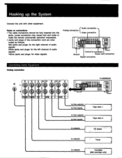
...cord are colorcoded as follows. player to outputs • !Tuner to outputs . Loose connection may cause hum and noise or make the remote commander operation impossible. • Jacks and plugs of audio signals Yellow jacks and plugs: for video signals Audio connection Analog, connection Video connection... connection Connecting Audio Equipment Analog connection IN IN DEC OUT tOI DEC OUT IN • • CU PNI NO TUNER C O -APE : O TAPE 1 TA-E2000ESD • a. • • 11)!II 044 OW.• • • mom ego 00 OD 00 to line outputs to line inputs : Tape...
...cord are colorcoded as follows. player to outputs • !Tuner to outputs . Loose connection may cause hum and noise or make the remote commander operation impossible. • Jacks and plugs of audio signals Yellow jacks and plugs: for video signals Audio connection Analog, connection Video connection... connection Connecting Audio Equipment Analog connection IN IN DEC OUT tOI DEC OUT IN • • CU PNI NO TUNER C O -APE : O TAPE 1 TA-E2000ESD • a. • • 11)!II 044 OW.• • • mom ego 00 OD 00 to line outputs to line inputs : Tape...
Primary User Manual
Page 12
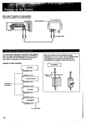
Wind the cord around it as close to the TA-E2000ESD as illustrated below. Close the ferrite core. TA-E2000ESD • 99 IIIHO 00 • **OA* ••q • WO • • • O CIO Center speakers TV or monitor TV to audio Inputs Connecting the Remote Control System To control other equipment connected to this amplifier...
Wind the cord around it as close to the TA-E2000ESD as illustrated below. Close the ferrite core. TA-E2000ESD • 99 IIIHO 00 • **OA* ••q • WO • • • O CIO Center speakers TV or monitor TV to audio Inputs Connecting the Remote Control System To control other equipment connected to this amplifier...

Primary User Manual
Page 14
El Remote control sensor El HEADPHONES jack Accepts the stereo phone plug of three levels. ID DIMMER button (page 32) Adjusts the brightness of the display to ...
El Remote control sensor El HEADPHONES jack Accepts the stereo phone plug of three levels. ID DIMMER button (page 32) Adjusts the brightness of the display to ...

Primary User Manual
Page 17
...indicated.) 0 PRESET/USER sound field number indication Indicates the number of the PRESET/USER select button setting or the number of the remote commander, the MEMORY indication appears when you press the MEMORY button and disappears when you press the sound field number button.) 09 REC...settings. El Sound field name indication Indicates the sound field name selected. O DIGITAL 1 2 3 indication Indicates the digital input selected by the remote commander. 11 DO PRO LOGIC DECODER indication Lights when the Pro Logic Decoder is indicated. DIGITAL : Input to the OPTICAL 2 IN jack ...
...indicated.) 0 PRESET/USER sound field number indication Indicates the number of the PRESET/USER select button setting or the number of the remote commander, the MEMORY indication appears when you press the MEMORY button and disappears when you press the sound field number button.) 09 REC...settings. El Sound field name indication Indicates the sound field name selected. O DIGITAL 1 2 3 indication Indicates the digital input selected by the remote commander. 11 DO PRO LOGIC DECODER indication Lights when the Pro Logic Decoder is indicated. DIGITAL : Input to the OPTICAL 2 IN jack ...

Primary User Manual
Page 18
...; : Stop 144 NI : AMS (Automatic Music Sensor)- VTR selector : Selects VCR 1, 2 or 3. El Mode selector (page 48) SONY STD: To control Sony equipment. El DISPLAY buttons MODE (display mode) button Selects the display in the following buttons when the TAPENTR selector is set to one of... Selects the equipment to confirm operation when storing the signals of other buttons or knobs, their indications light automatically for clgtgil Programmable Remote Commander RM-P2000 18 -EMI A -4=L_Cli IZ; El Input select buttons: Work in parentheses for several seconds.)-4tIl indications are...
...; : Stop 144 NI : AMS (Automatic Music Sensor)- VTR selector : Selects VCR 1, 2 or 3. El Mode selector (page 48) SONY STD: To control Sony equipment. El DISPLAY buttons MODE (display mode) button Selects the display in the following buttons when the TAPENTR selector is set to one of... Selects the equipment to confirm operation when storing the signals of other buttons or knobs, their indications light automatically for clgtgil Programmable Remote Commander RM-P2000 18 -EMI A -4=L_Cli IZ; El Input select buttons: Work in parentheses for several seconds.)-4tIl indications are...
Primary User Manual
Page 19
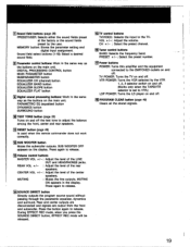
... amplifier and the equipment connected to adjust the balance among the front, center and rear speakers. 11 RESET button (page 49) Is used when the remote commander does not work correctly. MI PROGRAM CLEAR button (page 49) Clears all the stored signals. 19 ID Parameter control buttons: Work in the same...
... amplifier and the equipment connected to adjust the balance among the front, center and rear speakers. 11 RESET button (page 49) Is used when the remote commander does not work correctly. MI PROGRAM CLEAR button (page 49) Clears all the stored signals. 19 ID Parameter control buttons: Work in the same...

Primary User Manual
Page 20
.... NORMAL Select this amplifier. WIDE: Select this mode when you use medium-sized or large center speaker(s). This section describes the efficient placement of the remote commander, press the button number 10.) 3 Press the PRO LOGIC MODE button to select the mode according to adjust the speaker volume.
.... NORMAL Select this amplifier. WIDE: Select this mode when you use medium-sized or large center speaker(s). This section describes the efficient placement of the remote commander, press the button number 10.) 3 Press the PRO LOGIC MODE button to select the mode according to adjust the speaker volume.

Primary User Manual
Page 22
...) to PHANTOM): Front left and right -* Rear left and right alternately. s.7-4r+-1- • t lei . Adjust the speaker volume level from your listening position using the remote commander. 4 Press the TEST TONE button. OICIOCOGO00 ; aT g, CO CO CI CO lirc 1 4,6 . ..E:4.70 . PRESET appears in the display. 2 Press the DOLBY SURROUND button (10...
...) to PHANTOM): Front left and right -* Rear left and right alternately. s.7-4r+-1- • t lei . Adjust the speaker volume level from your listening position using the remote commander. 4 Press the TEST TONE button. OICIOCOGO00 ; aT g, CO CO CI CO lirc 1 4,6 . ..E:4.70 . PRESET appears in the display. 2 Press the DOLBY SURROUND button (10...
Primary User Manual
Page 23
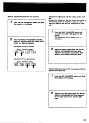
... right speaker level with the right DIGITAL PROCESSING CONTROL knob. Speaker level adjustment with the buttons on the main unit Speaker level adjustment with the remote commander at the listening position is desirable, but you can also adjust the speaker level with the buttons on the main unit 1 Press the SUB...
... right speaker level with the right DIGITAL PROCESSING CONTROL knob. Speaker level adjustment with the buttons on the main unit Speaker level adjustment with the remote commander at the listening position is desirable, but you can also adjust the speaker level with the buttons on the main unit 1 Press the SUB...

Primary User Manual
Page 26
... connected to make MUTING OFF appear. Chapter 2 Basic Operation „, Listening to/Watching Program Sources Enjoy playing back software on the remote commander to this amplifier. iOz3 r 3 0 0 0 =I 2 Play back the program source selected. 3 Adjust the volume with the... MASTER VOLUME knob. (In the case of the remote commander, press the MASTER VOL buttons.) 1 4 t MIX OM • • I= = c= i=r = ICI 015 0O 0 • • OD COI O02 CO O0 0 MOM 0 CO CM ...
... connected to make MUTING OFF appear. Chapter 2 Basic Operation „, Listening to/Watching Program Sources Enjoy playing back software on the remote commander to this amplifier. iOz3 r 3 0 0 0 =I 2 Play back the program source selected. 3 Adjust the volume with the... MASTER VOLUME knob. (In the case of the remote commander, press the MASTER VOL buttons.) 1 4 t MIX OM • • I= = c= i=r = ICI 015 0O 0 • • OD COI O02 CO O0 0 MOM 0 CO CM ...

Primary User Manual
Page 29
... on how to set each parameter, refer to 10.) See the table on page 34. Since these programs are appropriate for most types of the remote commander, press the button from 1 to "Creating your preference to use the sound fields preset at the factory. 1 2 O *Ca On • CO...
... on how to set each parameter, refer to 10.) See the table on page 34. Since these programs are appropriate for most types of the remote commander, press the button from 1 to "Creating your preference to use the sound fields preset at the factory. 1 2 O *Ca On • CO...

Primary User Manual
Page 42
... portion of the equalizer curve that exceeds *12dB will not be adjusted over a range from the flat condition Press the EQ CH button (with the remote commander, press the EQUALIZER CH button) to the analog input jacks, turn down the ANALOG input knob until the indication disappears. At this time, the...
... portion of the equalizer curve that exceeds *12dB will not be adjusted over a range from the flat condition Press the EQ CH button (with the remote commander, press the EQUALIZER CH button) to the analog input jacks, turn down the ANALOG input knob until the indication disappears. At this time, the...

Primary User Manual
Page 43
...Private Setting I=1 O° T 1 Doe •• 0 0 0 00 •O r T 2 12 OO OCI O*. 2 Press the SOUNDFIELD PROGRAM button (in the case of the remote commander, press any button from 1 to 10) to store your favorite sound. When storing the sound field by adjusting the parametric equalizer, dynamics and surround...MCI 03 00 03 m 0310 133 0 CO MD CM 01 O O co 1113 OOOO CM O O O O O O 2 M 03 CO 03 O CI 0G O O O O O 0 0 ococbm of the remote commander, this case, proceed again with step 1. . .. The MEMORY indication appears in which you have created your sound field.
...Private Setting I=1 O° T 1 Doe •• 0 0 0 00 •O r T 2 12 OO OCI O*. 2 Press the SOUNDFIELD PROGRAM button (in the case of the remote commander, press any button from 1 to 10) to store your favorite sound. When storing the sound field by adjusting the parametric equalizer, dynamics and surround...MCI 03 00 03 m 0310 133 0 CO MD CM 01 O O co 1113 OOOO CM O O O O O O 2 M 03 CO 03 O CI 0G O O O O O 0 0 ococbm of the remote commander, this case, proceed again with step 1. . .. The MEMORY indication appears in which you have created your sound field.

Primary User Manual
Page 48
...when the TAPE/VTR selector is set to VTR.) RESET You can use infrared rays, allowing you can store the functions of Sony equipment in other buttons of the remote commander in the same way as LDP (laser disc player), TUNER, TAPE, etc. If the indicator blinks, start again ... you to press the button designated as explained. For example, you can operate three Sony VCRs with the VTR1, 2 3 selector when the mode selector is to VTR. r --) Other manufacturer's remote control unit 4 Remove your remote commander supplied. You can freely store any function in any button, but to make the...
...when the TAPE/VTR selector is set to VTR.) RESET You can use infrared rays, allowing you can store the functions of Sony equipment in other buttons of the remote commander in the same way as LDP (laser disc player), TUNER, TAPE, etc. If the indicator blinks, start again ... you to press the button designated as explained. For example, you can operate three Sony VCRs with the VTR1, 2 3 selector when the mode selector is to VTR. r --) Other manufacturer's remote control unit 4 Remove your remote commander supplied. You can freely store any function in any button, but to make the...
Primary User Manual
Page 49
... REC button should be pressed together with the button on the format of the signal. Since the remote commander supplied can no signals have been stored Sony equipment can be remotely controlled even when the mode selector is reduced or storing may become difficult (the LEARN indicator will blink...). To clear all the stored signals USED STD 'I'll IIIIMIIPP" \NM al Set the mode selector to SONY STD. When Sony equipment works ...
... REC button should be pressed together with the button on the format of the signal. Since the remote commander supplied can no signals have been stored Sony equipment can be remotely controlled even when the mode selector is reduced or storing may become difficult (the LEARN indicator will blink...). To clear all the stored signals USED STD 'I'll IIIIMIIPP" \NM al Set the mode selector to SONY STD. When Sony equipment works ...

Primary User Manual
Page 51
Width when removing the side panels: 430mm (17 inches) Approx. 8.5 kg (18 lb 12oz) Programmable remote commander RM-P2000 (1) Sony Batteries SUM-3 (NS) (2) Audio connecting cord (3) Screw (4) Ferrite core (1) Design and specifications are subject to 500mS A/D, D/A converter section A/D converter Type: High density linear converter system ...
Width when removing the side panels: 430mm (17 inches) Approx. 8.5 kg (18 lb 12oz) Programmable remote commander RM-P2000 (1) Sony Batteries SUM-3 (NS) (2) Audio connecting cord (3) Screw (4) Ferrite core (1) Design and specifications are subject to 500mS A/D, D/A converter section A/D converter Type: High density linear converter system ...

Primary User Manual
Page 52
... REVERE 8fs OFF PULSE D/A I> 0 HEADPHONES ..111e(11 1 4-0 -10{>-•-0 0111-14-14 ADVANCED REAR REVERB 8fs D/F PULSE D/A FRONT 1.-111101 M4110.14I' An 0 REAR DIGITAL VE REMOTE SENSOR LED DRIVER 16bit CPU KEY INPUTS VIDEO 1 VIDEO 2 VIDEO 3 VIDEO 4 VIDEO 5 LD Tv MONITOR 1 VIDEO 1 OUT VIDEO 2 VIDEO 5 MONITOR 2 OUT LED INDICATORS MONITOR OUT...
... REVERE 8fs OFF PULSE D/A I> 0 HEADPHONES ..111e(11 1 4-0 -10{>-•-0 0111-14-14 ADVANCED REAR REVERB 8fs D/F PULSE D/A FRONT 1.-111101 M4110.14I' An 0 REAR DIGITAL VE REMOTE SENSOR LED DRIVER 16bit CPU KEY INPUTS VIDEO 1 VIDEO 2 VIDEO 3 VIDEO 4 VIDEO 5 LD Tv MONITOR 1 VIDEO 1 OUT VIDEO 2 VIDEO 5 MONITOR 2 OUT LED INDICATORS MONITOR OUT...


