

Limited Warranty (U.S. Only)
Page 1
... operation, call : 1-800-488-SONY (7669) Printed in the form of a bill of sale or receipted invoice which vary from the date of purchase, if this Product (including any part of the Product, including the antenna. This warranty gives you specific legal rights, and you may not apply to you. 4-243-341-02 General Stereo/Hifi Components/Tape Decks ® CD Players/Mini Disc Players/Audio...
... operation, call : 1-800-488-SONY (7669) Printed in the form of a bill of sale or receipted invoice which vary from the date of purchase, if this Product (including any part of the Product, including the antenna. This warranty gives you specific legal rights, and you may not apply to you. 4-243-341-02 General Stereo/Hifi Components/Tape Decks ® CD Players/Mini Disc Players/Audio...
Primary User Manual
Page 2
... and receiver are located at the rear. Government Printing Office, Washington DC 20402, Stock No. 004-000-00345-4. When the control S cord connection causes interference to identify and Resolve Ratio-TV Interference Problems". This apparatus complies with respect to radio and television reception. The user may be determined by the Federal Communications Commission helpful': "How to a TV or tuner, use the...
... and receiver are located at the rear. Government Printing Office, Washington DC 20402, Stock No. 004-000-00345-4. When the control S cord connection causes interference to identify and Resolve Ratio-TV Interference Problems". This apparatus complies with respect to radio and television reception. The user may be determined by the Federal Communications Commission helpful': "How to a TV or tuner, use the...
Primary User Manual
Page 3
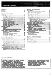
... 47 Pro Logic mode 20 Using the remote commander 48 Adjusting the speaker volume level 22 Storing signals 48 Adjusting the input level 24 Controlling equipment 49 Adjusting the delay time of the rear speakers 25 Chapter 4 Additional Information Chapter 2 Basic Operation Table of factory-preset parameters 50 Listening to/watching program sources 26 Specifications 51 Basic operation 26 Block diagram 52 Combining the video image with the sound Messages in the display 53 from another program source 27 Troubleshooting guide 54 Assigning digital audio input to...
... 47 Pro Logic mode 20 Using the remote commander 48 Adjusting the speaker volume level 22 Storing signals 48 Adjusting the input level 24 Controlling equipment 49 Adjusting the delay time of the rear speakers 25 Chapter 4 Additional Information Chapter 2 Basic Operation Table of factory-preset parameters 50 Listening to/watching program sources 26 Specifications 51 Basic operation 26 Block diagram 52 Combining the video image with the sound Messages in the display 53 from another program source 27 Troubleshooting guide 54 Assigning digital audio input to...
Primary User Manual
Page 4
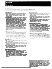
... more natural and warmer sound. numbers 3,632,886, 3,746,792, and 3,959,590. Additionally licensed under one remote commander. * Manufactured under license from a laser disc player or DAT deck to this amplifier. (Refer to directly connect digital output from Dolby Laboratories Licensing Corporation. The Pro Logic directionality emphasis circuitry gives a natural feel to the movement and position of sounds in the video program, making you feel as changing the input selection display...
... more natural and warmer sound. numbers 3,632,886, 3,746,792, and 3,959,590. Additionally licensed under one remote commander. * Manufactured under license from a laser disc player or DAT deck to this amplifier. (Refer to directly connect digital output from Dolby Laboratories Licensing Corporation. The Pro Logic directionality emphasis circuitry gives a natural feel to the movement and position of sounds in the video program, making you feel as changing the input selection display...
Primary User Manual
Page 8
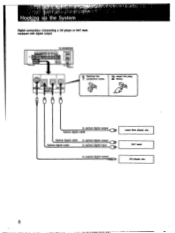
to optical digital output Optical digital cable Optical digital cable Optical digital cable to optical digital output to optical digital input to coaxial digital output Laser disc player, etc. IGITA OPT ALl Remove the protection cover. 2 Insert the plug firmly. DAT deck CD player, etc. 8 TA-E2000ESD 00 I RED 'UT COA AL 'PTICAL - 4.!1 Hooking the System Digital connection-Connecting a CD player or DAT deck equipped with digital output .. ..MM.
to optical digital output Optical digital cable Optical digital cable Optical digital cable to optical digital output to optical digital input to coaxial digital output Laser disc player, etc. IGITA OPT ALl Remove the protection cover. 2 Insert the plug firmly. DAT deck CD player, etc. 8 TA-E2000ESD 00 I RED 'UT COA AL 'PTICAL - 4.!1 Hooking the System Digital connection-Connecting a CD player or DAT deck equipped with digital output .. ..MM.
Primary User Manual
Page 12
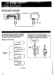
... core. Hooking up th-eSystem When using TV speakers as illustrated below. TA-E2000ESD • 99 IIIHO 00 • **OA* ••q • WO • • • O CIO Center speakers TV or monitor TV to audio Inputs Connecting the Remote Control System To control other equipment connected to this amplifier with the remote commander, connect the CONTROL S OUT connector and the CONTROL S IN connector of each piece of audio connection Tape deck CONTROL S IN CONTROL S connection CONTROL S OUT...
... core. Hooking up th-eSystem When using TV speakers as illustrated below. TA-E2000ESD • 99 IIIHO 00 • **OA* ••q • WO • • • O CIO Center speakers TV or monitor TV to audio Inputs Connecting the Remote Control System To control other equipment connected to this amplifier with the remote commander, connect the CONTROL S OUT connector and the CONTROL S IN connector of each piece of audio connection Tape deck CONTROL S IN CONTROL S connection CONTROL S OUT...

Primary User Manual
Page 14
... turn on each power amplifier or set the speaker select switch on the amplifier and the equipment connected to the program source only with the headphones, turn off the parametric equalizer. El Remote control sensor El HEADPHONES jack Accepts the stereo phone plug of three levels. To listen to the SWITCHED outlets. You can also use this button to one of headphones. ID Input select buttons and MIX button (page 26) Select the desired program source. When the dynamics function...
... turn on each power amplifier or set the speaker select switch on the amplifier and the equipment connected to the program source only with the headphones, turn off the parametric equalizer. El Remote control sensor El HEADPHONES jack Accepts the stereo phone plug of three levels. To listen to the SWITCHED outlets. You can also use this button to one of headphones. ID Input select buttons and MIX button (page 26) Select the desired program source. When the dynamics function...

Primary User Manual
Page 16
... parametric equalizer. E SET button (page 47) Sets the desired program source for an input select button or a sound field. Keep pressing + until just before OVER appears in the display. These signals are listening to the digital recording output jack (OPTICAL 2). El CLEAR button (page 28) Clear the digital equipment assigned to be adjusted by the SET button. El Ea CH (equalizer channel) button (pages 41 and 42) Selects the channel (front, center, rear or all the channels) to an input select button. wi ANALOG Input level...
... parametric equalizer. E SET button (page 47) Sets the desired program source for an input select button or a sound field. Keep pressing + until just before OVER appears in the display. These signals are listening to the digital recording output jack (OPTICAL 2). El CLEAR button (page 28) Clear the digital equipment assigned to be adjusted by the SET button. El Ea CH (equalizer channel) button (pages 41 and 42) Selects the channel (front, center, rear or all the channels) to an input select button. wi ANALOG Input level...

Primary User Manual
Page 17
... Indicates a sound field name, program source, operation mode or warning concerning incorrect operation. DIGITAL 0 : Input to the COAXIAL IN jack is selected. 0 Sampling frequency indicator Indicates the sampling frequency of the digital signal input. (For example, in the rear panel is selected. DIGITAL : Input to the OPTICAL 2 IN jack DIGITAL is selected. : Input to the OPTICAL 1 IN jack in the case of a CD, 44k is indicated.) 0 PRESET/USER sound field number indication Indicates the number of the PRESET/USER select button setting or the number of the remote commander, the...
... Indicates a sound field name, program source, operation mode or warning concerning incorrect operation. DIGITAL 0 : Input to the COAXIAL IN jack is selected. 0 Sampling frequency indicator Indicates the sampling frequency of the digital signal input. (For example, in the rear panel is selected. DIGITAL : Input to the OPTICAL 2 IN jack DIGITAL is selected. : Input to the OPTICAL 1 IN jack in the case of a CD, 44k is indicated.) 0 PRESET/USER sound field number indication Indicates the number of the PRESET/USER select button setting or the number of the remote commander, the...

Primary User Manual
Page 18
...) SONY STD: To control Sony equipment. DUAL : Selects bilingual programs. ANT TVNTR : Selects output signal from the antenna terminal on the main unit. (page 26) 18 USER STD: To control the equipment whose remote control functions are displayed. El Input select buttons: Work in the following buttons when the TAPENTR selector is used to one of this button to be controlled. ► : Play : Pause • : Stop 144 NI : AMS (Automatic Music Sensor)- El DISPLAY buttons MODE (display mode) button Selects the display in...
...) SONY STD: To control Sony equipment. DUAL : Selects bilingual programs. ANT TVNTR : Selects output signal from the antenna terminal on the main unit. (page 26) 18 USER STD: To control the equipment whose remote control functions are displayed. El Input select buttons: Work in the following buttons when the TAPENTR selector is used to one of this button to be controlled. ► : Play : Pause • : Stop 144 NI : AMS (Automatic Music Sensor)- El DISPLAY buttons MODE (display mode) button Selects the display in...
Primary User Manual
Page 19
... remote commander does not work correctly. CENTER VOL +/-: Adjust the level of the LINE OUT and HEADPHONES jacks. CH +/- : Select the preset channel. MI PROGRAM CLEAR button (page 49) Clears all the stored signals. 19 Sound field select buttons (1-10): Select a desired sound field. PARAMETRIC EQ (equalizer) button DYNAMICS button SURROUND button El TEST TONE button (page 22) Turns on the display. SUB WOOFER OFF appears on and off . EL Tuner control buttons BAND: Selects the frequency band. REAR VOL +/- : Adjust the level of the rear speakers. Press the button...
... remote commander does not work correctly. CENTER VOL +/-: Adjust the level of the LINE OUT and HEADPHONES jacks. CH +/- : Select the preset channel. MI PROGRAM CLEAR button (page 49) Clears all the stored signals. 19 Sound field select buttons (1-10): Select a desired sound field. PARAMETRIC EQ (equalizer) button DYNAMICS button SURROUND button El TEST TONE button (page 22) Turns on the display. SUB WOOFER OFF appears on and off . EL Tuner control buttons BAND: Selects the frequency band. REAR VOL +/- : Adjust the level of the rear speakers. Press the button...

Primary User Manual
Page 20
... adjust the speaker volume. This section describes the efficient placement of the speakers plays a very important role. We recommend that you place the speakers depends on the display. 2 Select preset number 10 by pressing the SOUNDFIELD PROGRAM button. (In the case of the rear speakers are used . Front (L) Front (R) Rear (L)6/ (4. Pro Logic mode is distributed to left and right front speakers equally since a center speaker is to your speakers. Each time you use small center speaker(s). The bass sound...
... adjust the speaker volume. This section describes the efficient placement of the speakers plays a very important role. We recommend that you place the speakers depends on the display. 2 Select preset number 10 by pressing the SOUNDFIELD PROGRAM button. (In the case of the rear speakers are used . Front (L) Front (R) Rear (L)6/ (4. Pro Logic mode is distributed to left and right front speakers equally since a center speaker is to your speakers. Each time you use small center speaker(s). The bass sound...

Primary User Manual
Page 21
... front speakers and one center speaker), set the PRO LOGIC MODE button to recreate the sound field of a two-channel Dolby Surround signal as it was developed by the creators of the movie. LOGIC. Thanks to Dolby Laboratories Licensing Corporation's unique directionality emphasis circuitry, sound imaging has been greatly improved, as can be seen in addition to obtain rich bass sound. Dolby Surround is not as directional as this amplifier...
... front speakers and one center speaker), set the PRO LOGIC MODE button to recreate the sound field of a two-channel Dolby Surround signal as it was developed by the creators of the movie. LOGIC. Thanks to Dolby Laboratories Licensing Corporation's unique directionality emphasis circuitry, sound imaging has been greatly improved, as can be seen in addition to obtain rich bass sound. Dolby Surround is not as directional as this amplifier...

Primary User Manual
Page 22
... to Enjoy Surround Sound Effect Adjusting the Speaker Volume Level To enjoy the surround sound to make this adjustment easy, use the test tone in DOLBY SURROUND mode. (The PRO LOGIC MODE button should be output in the xx positions.) When the center speaker is not used (The PRO LOGIC MODE button is set to stop the test tone. To make adjustments in any program source, adjustment of the speakers. Adjust the speaker volume level from your listening position using the remote commander. 4 Press the TEST TONE button. When the center speaker is used ) to...
... to Enjoy Surround Sound Effect Adjusting the Speaker Volume Level To enjoy the surround sound to make this adjustment easy, use the test tone in DOLBY SURROUND mode. (The PRO LOGIC MODE button should be output in the xx positions.) When the center speaker is not used (The PRO LOGIC MODE button is set to stop the test tone. To make adjustments in any program source, adjustment of the speakers. Adjust the speaker volume level from your listening position using the remote commander. 4 Press the TEST TONE button. When the center speaker is used ) to...

Primary User Manual
Page 24
For analog input, turn the ANALOG input level knob. For digital input, press the DIGITAL input level button (+) until OPTICAL1, OPTICAL2 or COAXIAL whichever is now complete. 4.; .,ry Getting Really to Enjoy Surround Effect Adjusting the Input Level (main unit only) Adjust the level of the audio/video equipment connected. • When the VISUAL or AUDIO indication appears in the display, press the MIX button to PHONO. Strictly speaking, you should adjust the input level each time you change the program source or surround mode. Play back...
For analog input, turn the ANALOG input level knob. For digital input, press the DIGITAL input level button (+) until OPTICAL1, OPTICAL2 or COAXIAL whichever is now complete. 4.; .,ry Getting Really to Enjoy Surround Effect Adjusting the Input Level (main unit only) Adjust the level of the audio/video equipment connected. • When the VISUAL or AUDIO indication appears in the display, press the MIX button to PHONO. Strictly speaking, you should adjust the input level each time you change the program source or surround mode. Play back...

Primary User Manual
Page 32
... 0.eration • "R What is possible in the following three areas. For this amplifier, digital signal processing is DS DSP (Digital Signal Processing) means that not only the digital signals but analog signals from a cassette deck or FM tuner, etc. See page 33. Parametric equalizer-PARAMETRIC E0 Controls the specific frequencies or output level to raise the bass sound or lower the treble sound. are indicated in succession in the display. In any button. 32
... 0.eration • "R What is possible in the following three areas. For this amplifier, digital signal processing is DS DSP (Digital Signal Processing) means that not only the digital signals but analog signals from a cassette deck or FM tuner, etc. See page 33. Parametric equalizer-PARAMETRIC E0 Controls the specific frequencies or output level to raise the bass sound or lower the treble sound. are indicated in succession in the display. In any button. 32

Primary User Manual
Page 37
... is simulated as 2.0, you adjust the parameter. Min Time ERef.Time=500mS (far from sound source) Level Early reflections Early reflection time 1?` Time 37 appears in the display. 2 3 4 Adjust the parameter. The Early Reflection Time is 124mS. ERef.Time=2mS (adjacent to sound source) Level Early reflections Early reflection time 1 Play back a program source. 2 Set the SURROUND button to reach the listening position. Early Reflection Time This parameter controls the time required for the early...
... is simulated as 2.0, you adjust the parameter. Min Time ERef.Time=500mS (far from sound source) Level Early reflections Early reflection time 1?` Time 37 appears in the display. 2 3 4 Adjust the parameter. The Early Reflection Time is 124mS. ERef.Time=2mS (adjacent to sound source) Level Early reflections Early reflection time 1 Play back a program source. 2 Set the SURROUND button to reach the listening position. Early Reflection Time This parameter controls the time required for the early...

Primary User Manual
Page 48
... signals at each position by switching the TAPENTR selector and VTR1,2,3 selector. (DUAL, ANT TVNTR, CH +/buttons can be programmed when the TAPE/VTR selector is set to VTR.) RESET You can store the functions of Sony equipment in the same way as LDP (laser disc player), TUNER, TAPE, etc. commander Indicatof lights. 3 Press the button of the remote commander in other buttons of the other manufacturer's remote control...
... signals at each position by switching the TAPENTR selector and VTR1,2,3 selector. (DUAL, ANT TVNTR, CH +/buttons can be programmed when the TAPE/VTR selector is set to VTR.) RESET You can store the functions of Sony equipment in the same way as LDP (laser disc player), TUNER, TAPE, etc. commander Indicatof lights. 3 Press the button of the remote commander in other buttons of the other manufacturer's remote control...

Primary User Manual
Page 51
... harmonic distortion Analog input Front: below 0.004% at 1kHz Digital input Front: below 0.003% at 8 ohms); Specifications Amplifier section Frequency response (Parametric EQ, Dynamics, Surround: OFF) Other than PHONO Front, Center*, Rear: 10 Hz-20kHz=0.1dB Subwoofer: Cut off 80Hz, 18dB/oct. Width when removing the side panels: 430mm (17 inches) Approx. 8.5 kg (18 lb 12oz) Programmable remote commander RM-P2000 (1) Sony Batteries SUM-3 (NS) (2) Audio connecting cord (3) Screw...
... harmonic distortion Analog input Front: below 0.004% at 1kHz Digital input Front: below 0.003% at 8 ohms); Specifications Amplifier section Frequency response (Parametric EQ, Dynamics, Surround: OFF) Other than PHONO Front, Center*, Rear: 10 Hz-20kHz=0.1dB Subwoofer: Cut off 80Hz, 18dB/oct. Width when removing the side panels: 430mm (17 inches) Approx. 8.5 kg (18 lb 12oz) Programmable remote commander RM-P2000 (1) Sony Batteries SUM-3 (NS) (2) Audio connecting cord (3) Screw...
Primary User Manual
Page 54
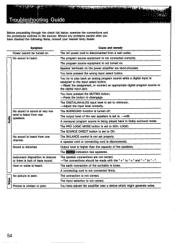
... to play back an analog program source while a digital input is heard from rear .2 speakers. The BALANCE control is set to the digital input jack. A connecting cord is heard. Should any problems persist after you have pressed the wrong input select button. Hum or noise is not connected firmly. Speaker terminals on the power amplifier are not correct. -The connections should be turned on . The SURROUND function is disconnected. The PRO LOGIC MODE button is not set to disengage. A speaker cord or connecting cord is turned off...
... to play back an analog program source while a digital input is heard from rear .2 speakers. The BALANCE control is set to the digital input jack. A connecting cord is heard. Should any problems persist after you have pressed the wrong input select button. Hum or noise is not connected firmly. Speaker terminals on the power amplifier are not correct. -The connections should be turned on . The SURROUND function is disconnected. The PRO LOGIC MODE button is not set to disengage. A speaker cord or connecting cord is turned off...


