
Instructions (SU-WL31 Wall-Mount Bracket)
Page 2
...* KLV-S26A1s* KLV-S23A1s* * In the actual model names, the "s" indicates numbers and/or characters specific to prevent such accidents. To customers in some models are supplied with a leaflet explaining how to the customer after installation. Sony is required for use the product correctly. Please give this manual to install the Wall-Mount Bracket ("Installing the Wall-Mount Bracket"). 2 (GB) To US customers Sufficient expertise is...
...* KLV-S26A1s* KLV-S23A1s* * In the actual model names, the "s" indicates numbers and/or characters specific to prevent such accidents. To customers in some models are supplied with a leaflet explaining how to the customer after installation. Sony is required for use the product correctly. Please give this manual to install the Wall-Mount Bracket ("Installing the Wall-Mount Bracket"). 2 (GB) To US customers Sufficient expertise is...

Instructions (SU-WL31 Wall-Mount Bracket)
Page 3
... of supporting a weight of at least four times the TV Do not mount any equipment other than the specified product. injury or property damage. Do not apply any kind on the TV. To Customers WARNING Do not spill liquid of any load other weight. (See the TV installing dimensions table on than the TV on the Wall-Mount Bracket...
... of supporting a weight of at least four times the TV Do not mount any equipment other than the specified product. injury or property damage. Do not apply any kind on the TV. To Customers WARNING Do not spill liquid of any load other weight. (See the TV installing dimensions table on than the TV on the Wall-Mount Bracket...

Instructions (SU-WL31 Wall-Mount Bracket)
Page 4
..., it on the wall, the screw holes are not observed, injury or property damage may cause a fire or an electric shock. If it may cause injury or property damage. candles) away from radio noise, etc.) before installing. Do not install the Wall-Mount Bracket on the Wall-Mount Bracket for a long time... mechanical vibrations. If a person or object happens to hit the protruded corner or side of the wall. • If the Wall-Mount Bracket is subjected to use the TV installed on wall surfaces where the corners or the sides of the TV. Do not handle the product with excessive force...
..., it on the wall, the screw holes are not observed, injury or property damage may cause a fire or an electric shock. If it may cause injury or property damage. candles) away from radio noise, etc.) before installing. Do not install the Wall-Mount Bracket on the Wall-Mount Bracket for a long time... mechanical vibrations. If a person or object happens to hit the protruded corner or side of the wall. • If the Wall-Mount Bracket is subjected to use the TV installed on wall surfaces where the corners or the sides of the TV. Do not handle the product with excessive force...

Instructions (SU-WL31 Wall-Mount Bracket)
Page 5
... in the designated position. If you use the appropriate screws for installing this instruction manual. Installing the WallMount Bracket To Sony Dealers WARNING to Customers Sufficient expertise is exposed to shock, it may fall or break apart. Be sure to use the supplied screws and attachment parts properly following instructions are loose or fall out, the Wall-Mount Bracket may fall and cause injury or...
... in the designated position. If you use the appropriate screws for installing this instruction manual. Installing the WallMount Bracket To Sony Dealers WARNING to Customers Sufficient expertise is exposed to shock, it may fall or break apart. Be sure to use the supplied screws and attachment parts properly following instructions are loose or fall out, the Wall-Mount Bracket may fall and cause injury or...

Instructions (SU-WL31 Wall-Mount Bracket)
Page 6
... electrical break. Step 1: Checking the parts required for the wall material and structure when mounting the Wall-Mount Bracket. If the AC power cord or the connecting cable is pinched between the unit and the wall or is supplied with a leaflet explaining how to install Wall-Mount Bracket ("Installing the Wall-Mount Bracket"), be pinched. Use the appropriate screws for the installation 1 Prepare five or more M6 or...
... electrical break. Step 1: Checking the parts required for the wall material and structure when mounting the Wall-Mount Bracket. If the AC power cord or the connecting cable is pinched between the unit and the wall or is supplied with a leaflet explaining how to install Wall-Mount Bracket ("Installing the Wall-Mount Bracket"), be pinched. Use the appropriate screws for the installation 1 Prepare five or more M6 or...

Instructions (SU-WL31 Wall-Mount Bracket)
Page 7
If you are installing the TV KDL-S23A1s*/KLVS23A1s*, do not change the position of the arm bases (Except for the TV KDL-S23A1s*/ KLV-S23A1s*) * In the actual model names, the "s" indicates numbers and/or characters specific to each assembly (stabilizer arm and arm ...base B) to the inner position, inserting the arm bases B into the top left and right Inner slots, and replace the screws from step 2. 6 Secure the stabilizer arms using an electric screwdriver, set the torque setting...
If you are installing the TV KDL-S23A1s*/KLVS23A1s*, do not change the position of the arm bases (Except for the TV KDL-S23A1s*/ KLV-S23A1s*) * In the actual model names, the "s" indicates numbers and/or characters specific to each assembly (stabilizer arm and arm ...base B) to the inner position, inserting the arm bases B into the top left and right Inner slots, and replace the screws from step 2. 6 Secure the stabilizer arms using an electric screwdriver, set the torque setting...
Instructions (SU-WL31 Wall-Mount Bracket)
Page 8
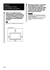
...installing dimensions table on page 16. 2 Referring to route the cables in the wall, also determine the position of the cable hole and bore a hole in the diagram below and decide on the installation location. WARNING The wall that the TV will be capable of supporting a weight of at least four times that of the screws... of the TV (page 16). Reinforce the wall sufficiently, if necessary. Step 3: Deciding on the installation location 1 Allow for suitable clearance between the TV and the ceiling and protruding parts of the wall as shown in the wall. Make sure of the strength of the...
...installing dimensions table on page 16. 2 Referring to route the cables in the wall, also determine the position of the cable hole and bore a hole in the diagram below and decide on the installation location. WARNING The wall that the TV will be capable of supporting a weight of at least four times that of the screws... of the TV (page 16). Reinforce the wall sufficiently, if necessary. Step 3: Deciding on the installation location 1 Allow for suitable clearance between the TV and the ceiling and protruding parts of the wall as shown in the wall. Make sure of the strength of the...

Instructions (SU-WL31 Wall-Mount Bracket)
Page 9
... temporarily attaching the Plate Unit 2 Secure the Plate Unit to the wall using a screw. WARNING The wall that the TV will be capable of supporting a weight of at least four times that of the wall. Align the unit so that the Plate Unit can support the weight of the display. 2 Tighten the screw used in procedure 1. Step 4: Installing the Plate Unit on .
... temporarily attaching the Plate Unit 2 Secure the Plate Unit to the wall using a screw. WARNING The wall that the TV will be capable of supporting a weight of at least four times that of the wall. Align the unit so that the Plate Unit can support the weight of the display. 2 Tighten the screw used in procedure 1. Step 4: Installing the Plate Unit on .

Instructions (SU-WL31 Wall-Mount Bracket)
Page 10
... the operating instructions or the leaflet ("Installing the Wall-Mount Bracket") supplied with its screen facing down, on the TV. KDL-V32A1s*/KLV-V32A1s*/ KDL-V32XBR1 A KDL-V26A1s*/KLV-V26A1s*/ KDL-V26XBR1 B KDL-S32A1s*/KLV-S32A1s C KDL-S26A1s*/KLV-S26A1s D KDL-S23A1s*/KLV-S23A1s E * In the actual model names, the "s" indicates numbers and/or characters specific to each...
... the operating instructions or the leaflet ("Installing the Wall-Mount Bracket") supplied with its screen facing down, on the TV. KDL-V32A1s*/KLV-V32A1s*/ KDL-V32XBR1 A KDL-V26A1s*/KLV-V26A1s*/ KDL-V26XBR1 B KDL-S32A1s*/KLV-S32A1s C KDL-S26A1s*/KLV-S26A1s D KDL-S23A1s*/KLV-S23A1s E * In the actual model names, the "s" indicates numbers and/or characters specific to each...

Instructions (SU-WL31 Wall-Mount Bracket)
Page 11
AB Cable holder 4 Remove the four screws that hold the TableTop Stand to the TV and detach the Table-Top Stand from the TV (C D E only). C Hinge cover D Hinge cover CDE E Hinge cover 2 Attach the Mounting Hook Units to the TV and detach the hinge cover from the TV. A Screw (+PSW5 × L16) Mounting Hook Unit 11 (GB) CD These will be used in procedure 2 (C only). AB 3 Remove the screws that hold the hinge cover to the TV with the supplied four screws (+PSW5 × L16). 2 Rotate the cable holder by 90 degrees, and pull the cable holder out (A B only).
AB Cable holder 4 Remove the four screws that hold the TableTop Stand to the TV and detach the Table-Top Stand from the TV (C D E only). C Hinge cover D Hinge cover CDE E Hinge cover 2 Attach the Mounting Hook Units to the TV and detach the hinge cover from the TV. A Screw (+PSW5 × L16) Mounting Hook Unit 11 (GB) CD These will be used in procedure 2 (C only). AB 3 Remove the screws that hold the hinge cover to the TV with the supplied four screws (+PSW5 × L16). 2 Rotate the cable holder by 90 degrees, and pull the cable holder out (A B only).
Instructions (SU-WL31 Wall-Mount Bracket)
Page 12
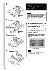
...Installing the TV on the Plate Unit C Screw (+PSW5 × L16) Retighten two screws removed in 3 of equipment, this may hurt yourself. 1 Connect the AC power cord and the connecting cable(s) supplied with the TV to licensed contractors. 12 (GB) Mounting Hook Unit When you allow the AC power cord to the instruction manual...). Connect the AC power cord and the connecting cable(s) to the wall outlet. D Screw (+PSW5 × L16) Mounting Hook Unit Mounting Hook Unit WARNING Be sure to complete the installation before connecting the AC power cord to the connectors on the Plate Unit...
...Installing the TV on the Plate Unit C Screw (+PSW5 × L16) Retighten two screws removed in 3 of equipment, this may hurt yourself. 1 Connect the AC power cord and the connecting cable(s) supplied with the TV to licensed contractors. 12 (GB) Mounting Hook Unit When you allow the AC power cord to the instruction manual...). Connect the AC power cord and the connecting cable(s) to the wall outlet. D Screw (+PSW5 × L16) Mounting Hook Unit Mounting Hook Unit WARNING Be sure to complete the installation before connecting the AC power cord to the connectors on the Plate Unit...
Instructions (SU-WL31 Wall-Mount Bracket)
Page 13
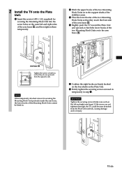
...and right arm bases). WARNING Tighten the securing screws firmly (one each on the Plate Unit. 6 Firmly tighten the securing screws screwed in temporarily in step 1. 2 Install the TV onto the Plate Unit. 1 Insert the screws (+B5 × L12, supplied) for securing the Mounting Hook Unit protrude inside the arm bases, the...arm bases B, and then tighten them temporarily. 2 Hitch the upper hooks of the two Mounting Hook Units on to the support shafts of the stabilizer arms. 3 Place the lower hooks of the two Mounting Hook Units so that they touch the front side of the arm bases B. 4 Slightly ...
...and right arm bases). WARNING Tighten the securing screws firmly (one each on the Plate Unit. 6 Firmly tighten the securing screws screwed in temporarily in step 1. 2 Install the TV onto the Plate Unit. 1 Insert the screws (+B5 × L12, supplied) for securing the Mounting Hook Unit protrude inside the arm bases, the...arm bases B, and then tighten them temporarily. 2 Hitch the upper hooks of the two Mounting Hook Units on to the support shafts of the stabilizer arms. 3 Place the lower hooks of the two Mounting Hook Units so that they touch the front side of the arm bases B. 4 Slightly ...

Instructions (SU-WL31 Wall-Mount Bracket)
Page 14
... circuit. Confirming the completion of the installation Check the following points. • Eight hooks of the Mounting Hook Units are firmly hooked on the four shafts of the stabilizer arms. • The cord and the cable are not twisted or pinched. • The two securing screws on the right and left arm bases... when removing the TV. • Be careful not to hurt your hands or fingers when removing the TV. 14 (GB) When removing the TV To Sony Dealers 1 Unplug the AC power cord from the wall outlet. 2 Remove the two securing screws on the arm bases are securely tightened.
... circuit. Confirming the completion of the installation Check the following points. • Eight hooks of the Mounting Hook Units are firmly hooked on the four shafts of the stabilizer arms. • The cord and the cable are not twisted or pinched. • The two securing screws on the right and left arm bases... when removing the TV. • Be careful not to hurt your hands or fingers when removing the TV. 14 (GB) When removing the TV To Sony Dealers 1 Unplug the AC power cord from the wall outlet. 2 Remove the two securing screws on the arm bases are securely tightened.

Instructions (SU-WL31 Wall-Mount Bracket)
Page 15
210 (8 9⁄32) 245 (9 21⁄32) 270 (10 5⁄8) Specifications Unit: mm (inches) Weight: 3.4 kg (7 lb 8 oz) Design and specifications are subject to change without notice. PLATE UNIT 500 (19 11⁄16) MOUNTING HOOK UNIT 40 (1 9⁄16) 15 (GB)
210 (8 9⁄32) 245 (9 21⁄32) 270 (10 5⁄8) Specifications Unit: mm (inches) Weight: 3.4 kg (7 lb 8 oz) Design and specifications are subject to change without notice. PLATE UNIT 500 (19 11⁄16) MOUNTING HOOK UNIT 40 (1 9⁄16) 15 (GB)

Instructions (SU-WL31 Wall-Mount Bracket)
Page 16
...Wall-Mount Bracket is designed for each model. ** The wall that of the TV. For other TVs and monitors, refer to their operating instructions to check if this Wall-Mount Bracket can be capable of supporting a weight of at least four times that the TV will be installed on the installation. * In the actual model names, the "s" indicates numbers and/or characters specific... Length for use with a leaflet including the TV/monitor installing dimensions table ("Installing the Wall-Mount Bracket"). 16 (GB) 210 (8 9/32) 14 (9/16) 210 (8 9/32) 14 (9/16) TV installing dimensions table KDL-S26A1s...
...Wall-Mount Bracket is designed for each model. ** The wall that of the TV. For other TVs and monitors, refer to their operating instructions to check if this Wall-Mount Bracket can be capable of supporting a weight of at least four times that the TV will be installed on the installation. * In the actual model names, the "s" indicates numbers and/or characters specific... Length for use with a leaflet including the TV/monitor installing dimensions table ("Installing the Wall-Mount Bracket"). 16 (GB) 210 (8 9/32) 14 (9/16) 210 (8 9/32) 14 (9/16) TV installing dimensions table KDL-S26A1s...

Instructions (SU-WL31 Wall-Mount Bracket)
Page 17
Wall processing dimensions diagram Unit: mm (inches) 500 (19 11/16) 454 (17 7/8) 430 (16 15/16) 215 (8 15/32) 9-7×40 (9/32 × 1 9/16) Slot hole 14 (9/16) 91 (3 19/32) 148 (5 13/16) 25 25 25 (31/32) (31/32) (31/32) 210 (8 9/32) 25 25 25 (31/32) (31/32) (31/32) φ60 (2 3/8) Hole for cable routing 12-φ7 (φ9/32) 17 (GB)
Wall processing dimensions diagram Unit: mm (inches) 500 (19 11/16) 454 (17 7/8) 430 (16 15/16) 215 (8 15/32) 9-7×40 (9/32 × 1 9/16) Slot hole 14 (9/16) 91 (3 19/32) 148 (5 13/16) 25 25 25 (31/32) (31/32) (31/32) 210 (8 9/32) 25 25 25 (31/32) (31/32) (31/32) φ60 (2 3/8) Hole for cable routing 12-φ7 (φ9/32) 17 (GB)

Installation
Page 1
...Instructions for the SU-WL31. 1 Connect the AC power cord and cables to support at least four times the weight of this installation supplement as well as í como las instrucciones (suministradas con el soporte de montaje mural SUWL31). Please refer to the Installation Dimensions Table to the Instructions...está instalando. Refer to the Instructions for your TV's model number and be wall-mounted using SU-WL31 Wall-Mount Bracket (sold separately). Notes • Lay the display face down on the rear of the surface. Step 6: Installing the TV on the Plate Unit Refer ...
...Instructions for the SU-WL31. 1 Connect the AC power cord and cables to support at least four times the weight of this installation supplement as well as í como las instrucciones (suministradas con el soporte de montaje mural SUWL31). Please refer to the Installation Dimensions Table to the Instructions...está instalando. Refer to the Instructions for your TV's model number and be wall-mounted using SU-WL31 Wall-Mount Bracket (sold separately). Notes • Lay the display face down on the rear of the surface. Step 6: Installing the TV on the Plate Unit Refer ...

