
SUPW1 Wall Mount Supplement
Page 1
... be taken when making holes in the wall for the cables (supplementary instruction for improper assembly or handling that are not strong enough to support the weight, are not flat, or are followed during the installation. On walls with the Sony KLV30XBR900 LCD Color TV. Sony cannot assume responsibility for step 4) Be careful when you mount the display. The wall must be attached...
... be taken when making holes in the wall for the cables (supplementary instruction for improper assembly or handling that are not strong enough to support the weight, are not flat, or are followed during the installation. On walls with the Sony KLV30XBR900 LCD Color TV. Sony cannot assume responsibility for step 4) Be careful when you mount the display. The wall must be attached...

SUPW1 Wall Mount Supplement
Page 2
...Step 4: Install the Display Unit" on page 11 (US) of the stand. Attaching the plate unit to disengage the hooks (at the bottom of the plate as shown in the supplied Instructions, to the Wall-Mount Bracket. C 530...dimensions given in the diagram below are those in the diagram. Following the instructions given in the diagram. Supplementary instructions for installing an LCD Color TV 2 During installation, follow the supplementary instructions given below, as well as those required for proper installation. Remove the two fixing screws from the vertical plate of the Instructions...
...Step 4: Install the Display Unit" on page 11 (US) of the stand. Attaching the plate unit to disengage the hooks (at the bottom of the plate as shown in the supplied Instructions, to the Wall-Mount Bracket. C 530...dimensions given in the diagram below are those in the diagram. Following the instructions given in the diagram. Supplementary instructions for installing an LCD Color TV 2 During installation, follow the supplementary instructions given below, as well as those required for proper installation. Remove the two fixing screws from the vertical plate of the Instructions...
Dimensions Diagram
Page 1
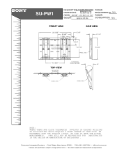
... specifications subject to change without notice. • Non-metric weights and measurements are approximate. SONY WILL NOT BE RESPONSIBLE FOR INACCURACIES IN THE DESIGN OR MANUFACTURE OF ENCLOSURES . SU-PW1 DESCRIPTION: PLASMA MOUNTING DIMENSIONS BRACKET FOR KE-XBR 42& 50 (WHD): 23 5/8 " x 15 3/4" x 2 1/4" WEIGHT: Approx 20 lbs POWER REQUIREMENTS: N/A POWER CONSUMPTION: N/A FRONT VIEW 23 5/8" 9 5/8" 1 3/8" 15 deg Tilt 10 deg Tilt 0 deg Tilt 1 3/8" SIDE VIEW 2 1/4" 5 3/4" *12 1/4" PANEL...
... specifications subject to change without notice. • Non-metric weights and measurements are approximate. SONY WILL NOT BE RESPONSIBLE FOR INACCURACIES IN THE DESIGN OR MANUFACTURE OF ENCLOSURES . SU-PW1 DESCRIPTION: PLASMA MOUNTING DIMENSIONS BRACKET FOR KE-XBR 42& 50 (WHD): 23 5/8 " x 15 3/4" x 2 1/4" WEIGHT: Approx 20 lbs POWER REQUIREMENTS: N/A POWER CONSUMPTION: N/A FRONT VIEW 23 5/8" 9 5/8" 1 3/8" 15 deg Tilt 10 deg Tilt 0 deg Tilt 1 3/8" SIDE VIEW 2 1/4" 5 3/4" *12 1/4" PANEL...

Instructions (primary manual)
Page 1
4-092-246-12 (1) For Customers and Sony Dealers in North and Central America Wall-Mount Bracket Instructions US Manuel d'instructions FR Manual de instrucciones ES SU-PW1 © 2002 Sony Corporation
4-092-246-12 (1) For Customers and Sony Dealers in North and Central America Wall-Mount Bracket Instructions US Manuel d'instructions FR Manual de instrucciones ES SU-PW1 © 2002 Sony Corporation
Instructions (primary manual)
Page 2
... result in serious injury through a fire, an electric shock or by Sony for use this product. If the product is used incorrectly, however, it may result in a fire or serious injury. Thank you for purchasing this instruction manual thoroughly to do the installation work safely. This Wall-Mount Bracket is required for future reference. WARNING If the safety precautions are...
... result in serious injury through a fire, an electric shock or by Sony for use this product. If the product is used incorrectly, however, it may result in a fire or serious injury. Thank you for purchasing this instruction manual thoroughly to do the installation work safely. This Wall-Mount Bracket is required for future reference. WARNING If the safety precautions are...
Instructions (primary manual)
Page 3
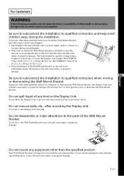
... the Wall-Mount Bracket. Do not disassemble or make alterations to the floor, the unit may fall and cause injury or property damage. Do not mount any kind on which the Wall-Mount Bracket is installed is designed for use with the specified product. Do not remove bolts, etc., after mounting the Display Unit. This Wall-Mount Bracket is unstable, uneven, or not perpendicular to the parts of...
... the Wall-Mount Bracket. Do not disassemble or make alterations to the floor, the unit may fall and cause injury or property damage. Do not mount any kind on which the Wall-Mount Bracket is installed is designed for use with the specified product. Do not remove bolts, etc., after mounting the Display Unit. This Wall-Mount Bracket is unstable, uneven, or not perpendicular to the parts of...
Instructions (primary manual)
Page 4
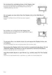
... an electric shock, do so, this may fall and the user may be exposed to get wet, this may result in hot, humid or excessively dusty places. Do not install the Display Unit where it may be caught under the weight of the Display Unit with a cloth or the like, the... Display Unit may become overheated and this may cause a fire. To prevent a fire, keep flammable objects or open flames (e.g. Do not block the ventilating holes on the Wall-Mount Bracket. If...
... an electric shock, do so, this may fall and the user may be exposed to get wet, this may result in hot, humid or excessively dusty places. Do not install the Display Unit where it may be caught under the weight of the Display Unit with a cloth or the like, the... Display Unit may become overheated and this may cause a fire. To prevent a fire, keep flammable objects or open flames (e.g. Do not block the ventilating holes on the Wall-Mount Bracket. If...
Instructions (primary manual)
Page 5
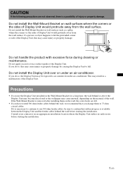
...the Wall-Mount Bracket is removed after installing them to use the Display Unit installed on the material of injury or property damage. If it is necessary to continue to 75 ohm coaxial cables.... Wall-Mount Bracket for a long time, the wall behind the wall before starting the installation. Precautions • If you use 300 ohm feeder cables, be exposed to confirm that you change them on the wall,...apply excessive force on an appropriate installation location where the Display Unit suffers no radio noise before starting the installation. 5 (US) Consult your contractor on the...
...the Wall-Mount Bracket is removed after installing them to use the Display Unit installed on the material of injury or property damage. If it is necessary to continue to 75 ohm coaxial cables.... Wall-Mount Bracket for a long time, the wall behind the wall before starting the installation. Precautions • If you use 300 ohm feeder cables, be exposed to confirm that you change them on the wall,...apply excessive force on an appropriate installation location where the Display Unit suffers no radio noise before starting the installation. 5 (US) Consult your contractor on the...
Instructions (primary manual)
Page 6
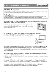
... damage to use the supplied screws and attachment parts properly following the instructions in this product. Install the Wall-Mount Bracket For Sony Dealers WARNING To Customers Sufficient expertise is required for Sony Dealers only. Be sure to read safety precautions described above and pay adequate attention to the wall following the instructions given in the cord or cable. Be sure to install the Wall-Mount Bracket securely...
... damage to use the supplied screws and attachment parts properly following the instructions in this product. Install the Wall-Mount Bracket For Sony Dealers WARNING To Customers Sufficient expertise is required for Sony Dealers only. Be sure to read safety precautions described above and pay adequate attention to the wall following the instructions given in the cord or cable. Be sure to install the Wall-Mount Bracket securely...

Instructions (primary manual)
Page 7
...Plate Unit (1) Mounting Hook Unit (2) 7 (US) Use the appropriate screws for the installation 1 Prepare a Phillips driver and the appropriate screws (eight or more M8 or the equivalent screws, not supplied), depending on a wall that is both perpendicular and flat. Be sure to install the Display Unit ... Unit, secure the cables properly. The screws needed to secure the Wall-Mount Bracket to hurt your hands or fingers when installing the Wall-Mount Bracket or the Display Unit. After proper installation of the wall, beforehand. 2 Open the package and check the parts. If people or ...
...Plate Unit (1) Mounting Hook Unit (2) 7 (US) Use the appropriate screws for the installation 1 Prepare a Phillips driver and the appropriate screws (eight or more M8 or the equivalent screws, not supplied), depending on a wall that is both perpendicular and flat. Be sure to install the Display Unit ... Unit, secure the cables properly. The screws needed to secure the Wall-Mount Bracket to hurt your hands or fingers when installing the Wall-Mount Bracket or the Display Unit. After proper installation of the wall, beforehand. 2 Open the package and check the parts. If people or ...

Instructions (primary manual)
Page 8
... section diagram in "Specifications" (p.15 (US)) for temporarily attaching the bracket. Screw hole to be used for details on dimensions when the Display Unit is installed on the wall. 100 (3 15⁄16) Step 3: Install the Plate Unit on the material and structure of the Plate Unit so that it is exactly level. WARNING • The screws securing the Wall-Mount Bracket...
... section diagram in "Specifications" (p.15 (US)) for temporarily attaching the bracket. Screw hole to be used for details on dimensions when the Display Unit is installed on the wall. 100 (3 15⁄16) Step 3: Install the Plate Unit on the material and structure of the Plate Unit so that it is exactly level. WARNING • The screws securing the Wall-Mount Bracket...

Instructions (primary manual)
Page 9
If the Plate Unit cannot be attached securely enough, use additional screws. • Be sure to confirm that they will not come loose. 2Firmly tighten the screw screwed in temporarily in the diagram on the left when attaching the Plate Unit temporarily. KE-42XBR900/KE-50XBR900 530 ...182 (5 31⁄32) (7) (7 5⁄32) 9 (US) 2 Fix the Plate Unit to the wall using the screw hole locations specified in Procedure 1. WARNING • We recommend using 2 eight or more M8 or the equivalent screws (not supplied). 1 1Be sure to tighten the screws securely so that the Plate Unit ...
If the Plate Unit cannot be attached securely enough, use additional screws. • Be sure to confirm that they will not come loose. 2Firmly tighten the screw screwed in temporarily in the diagram on the left when attaching the Plate Unit temporarily. KE-42XBR900/KE-50XBR900 530 ...182 (5 31⁄32) (7) (7 5⁄32) 9 (US) 2 Fix the Plate Unit to the wall using the screw hole locations specified in Procedure 1. WARNING • We recommend using 2 eight or more M8 or the equivalent screws (not supplied). 1 1Be sure to tighten the screws securely so that the Plate Unit ...

Instructions (primary manual)
Page 11
... Mounting Hook Unit and fix it using the supplied screws (+PSW5 × 12). If you allow the Power Cord to the wall outlet. Step 4: Install the Display Unit WARNING Be sure to complete the installation before connecting the Power Cord to be pinched under or between pieces of the Display Unit 11 (US) If you stumble over the Power Cord or the Display Interface Cable, the stand...
... Mounting Hook Unit and fix it using the supplied screws (+PSW5 × 12). If you allow the Power Cord to the wall outlet. Step 4: Install the Display Unit WARNING Be sure to complete the installation before connecting the Power Cord to be pinched under or between pieces of the Display Unit 11 (US) If you stumble over the Power Cord or the Display Interface Cable, the stand...
Instructions (primary manual)
Page 12
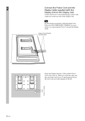
... Display Cable to the connectors on the rear side of the Flat Panel Color Television (KE-42XBR900/KE-50XBR900) for more details on connecting the Power Cord and the Display Cable. Tip See the instruction manual of the Display Unit. When you route the cable and the cord in the wall, bore a 50 mm diameter hole in the wall as shown in the diagram in...
... Display Cable to the connectors on the rear side of the Flat Panel Color Television (KE-42XBR900/KE-50XBR900) for more details on connecting the Power Cord and the Display Cable. Tip See the instruction manual of the Display Unit. When you route the cable and the cord in the wall, bore a 50 mm diameter hole in the wall as shown in the diagram in...

Instructions (primary manual)
Page 13
3 2 4 Install the Display Unit on the Plate Unit. 1Hold the Display Unit and bring it close to the Plate Unit so as to align the lower hooks of the Mounting Hook Units with the lowest support shafts near the bottom of the Plate Unit. 2Hitch the upper and lower hooks of the two Mounting Hook Units onto the four support shafts of the Plate Unit all at the same time as shown in the diagram on the left. 3Confirm the eight hooks are firmly hooked on the four shafts on the Plate Unit. 4Firmly tighten the securing screws on the right and the left with a long shaft Phillips screwdriver. 13 (US)
3 2 4 Install the Display Unit on the Plate Unit. 1Hold the Display Unit and bring it close to the Plate Unit so as to align the lower hooks of the Mounting Hook Units with the lowest support shafts near the bottom of the Plate Unit. 2Hitch the upper and lower hooks of the two Mounting Hook Units onto the four support shafts of the Plate Unit all at the same time as shown in the diagram on the left. 3Confirm the eight hooks are firmly hooked on the four shafts on the Plate Unit. 4Firmly tighten the securing screws on the right and the left with a long shaft Phillips screwdriver. 13 (US)

Instructions (primary manual)
Page 14
WARNING • Be sure that two or more persons hold the Display Unit and slide it . • Be careful not to allow the cords and cables to get hung up when removing the Display Unit. • Be careful not to remove the Display Unit. Removing the Display Unit For Sony Dealers 1 Unplug the Power Cord from the wall outlet. 2 Loosen the securing screws on the right and left until they will not turn any more. 3 Be sure that two or more persons hold the Display Unit when carrying it upward to hurt your hands or fingers when removing the Display Unit. 14 (US)
WARNING • Be sure that two or more persons hold the Display Unit and slide it . • Be careful not to allow the cords and cables to get hung up when removing the Display Unit. • Be careful not to remove the Display Unit. Removing the Display Unit For Sony Dealers 1 Unplug the Power Cord from the wall outlet. 2 Loosen the securing screws on the right and left until they will not turn any more. 3 Be sure that two or more persons hold the Display Unit when carrying it upward to hurt your hands or fingers when removing the Display Unit. 14 (US)

Instructions (primary manual)
Page 15
Specifications Unit: mm (inches) Weight: 8.0 kg (17 lb 10 oz) Design and specifications are subject to change without notice. 400 (15 3⁄4) 385 (15 3⁄32) A 600 (23 5⁄8) 51 (2) B a ...8260;32) 720 (28 11⁄32) 720 (28 11⁄32) 720 (28 11⁄32) Unit: mm (inches) Dimensions B C 160 173 (6 5⁄16) (6 13⁄16) 207 162 (8 5⁄32) (6 3⁄8) 253 148 (9 ...) 856 (33 11⁄16) 856 (33 11⁄16) 856 (33 11⁄16) Unit: mm (inches) Dimensions B C 166 307 (6 17⁄32) (12 3⁄32) 225 296 (8 27⁄32) (11 21⁄...
Specifications Unit: mm (inches) Weight: 8.0 kg (17 lb 10 oz) Design and specifications are subject to change without notice. 400 (15 3⁄4) 385 (15 3⁄32) A 600 (23 5⁄8) 51 (2) B a ...8260;32) 720 (28 11⁄32) 720 (28 11⁄32) 720 (28 11⁄32) Unit: mm (inches) Dimensions B C 160 173 (6 5⁄16) (6 13⁄16) 207 162 (8 5⁄32) (6 3⁄8) 253 148 (9 ...) 856 (33 11⁄16) 856 (33 11⁄16) 856 (33 11⁄16) Unit: mm (inches) Dimensions B C 166 307 (6 17⁄32) (12 3⁄32) 225 296 (8 27⁄32) (11 21⁄...

Instructions (primary manual)
Page 16
... installation, misapplication, setup, improper maintenance, commercial use, or modification of, or to : C • Name Address City State Zip Code Phone Model Part No. If any parts are determined to be presented to the original purchaser. Some states do not allow limitations on this product against defects in the assembly manual, identify the missing or damaged part, and call the Sony Customer Service Center...
... installation, misapplication, setup, improper maintenance, commercial use, or modification of, or to : C • Name Address City State Zip Code Phone Model Part No. If any parts are determined to be presented to the original purchaser. Some states do not allow limitations on this product against defects in the assembly manual, identify the missing or damaged part, and call the Sony Customer Service Center...

Instructions (primary manual)
Page 32
... from the date of sale or receipted invoice, which is evidence that are missing or damaged, please review the parts list found in shipment or failures due to acts of God, accident, misuse, abuse, negligence, faulty installation, misapplication, setup, improper maintenance, commercial use, or modification of, or to : C • Name Address City State Zip Code Phone Model Part No. This warranty...
... from the date of sale or receipted invoice, which is evidence that are missing or damaged, please review the parts list found in shipment or failures due to acts of God, accident, misuse, abuse, negligence, faulty installation, misapplication, setup, improper maintenance, commercial use, or modification of, or to : C • Name Address City State Zip Code Phone Model Part No. This warranty...

Instructions (primary manual)
Page 48
...you will supply parts that are missing or damaged, please review the parts list found in material or workmanship, subject to the original purchaser. In order to : C • Name Address City State Zip Code Phone Model Part No. ...partes que se encuentra en el manual de ensamble, identifique la parte dañada of Sony Wall-Mount Bracket parts and components. 2. This warranty gives you specific legal rights, and you must be presented to state. This warranty is within the warranty period, must provide a PROOF OF PURCHASE and complete the information...
...you will supply parts that are missing or damaged, please review the parts list found in material or workmanship, subject to the original purchaser. In order to : C • Name Address City State Zip Code Phone Model Part No. ...partes que se encuentra en el manual de ensamble, identifique la parte dañada of Sony Wall-Mount Bracket parts and components. 2. This warranty gives you specific legal rights, and you must be presented to state. This warranty is within the warranty period, must provide a PROOF OF PURCHASE and complete the information...


